TRANSMISSION
A/T Wiring Diagram (1 of 2) for Mitsubishi Outlander SE 2014

List of elements for A/T Wiring Diagram (1 of 2) for Mitsubishi Outlander SE 2014:
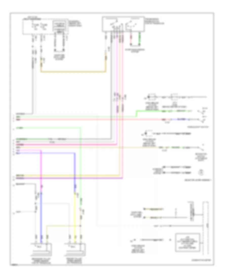
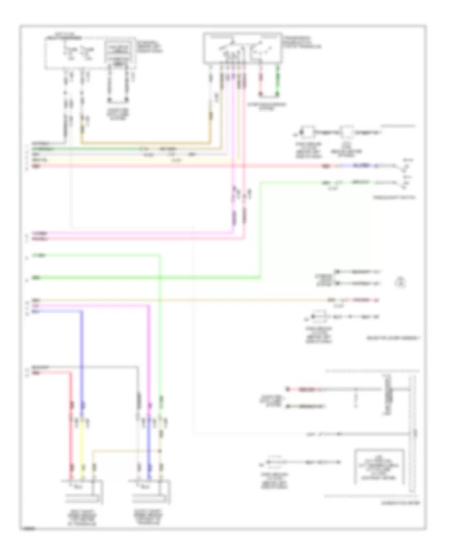
A/T Wiring Diagram (2 of 2) for Mitsubishi Outlander SE 2014
List of elements for A/T Wiring Diagram (2 of 2) for Mitsubishi Outlander SE 2014:
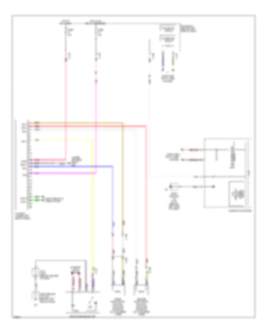
AWC Wiring Diagram for Mitsubishi Outlander SE 2014
List of elements for AWC Wiring Diagram for Mitsubishi Outlander SE 2014:
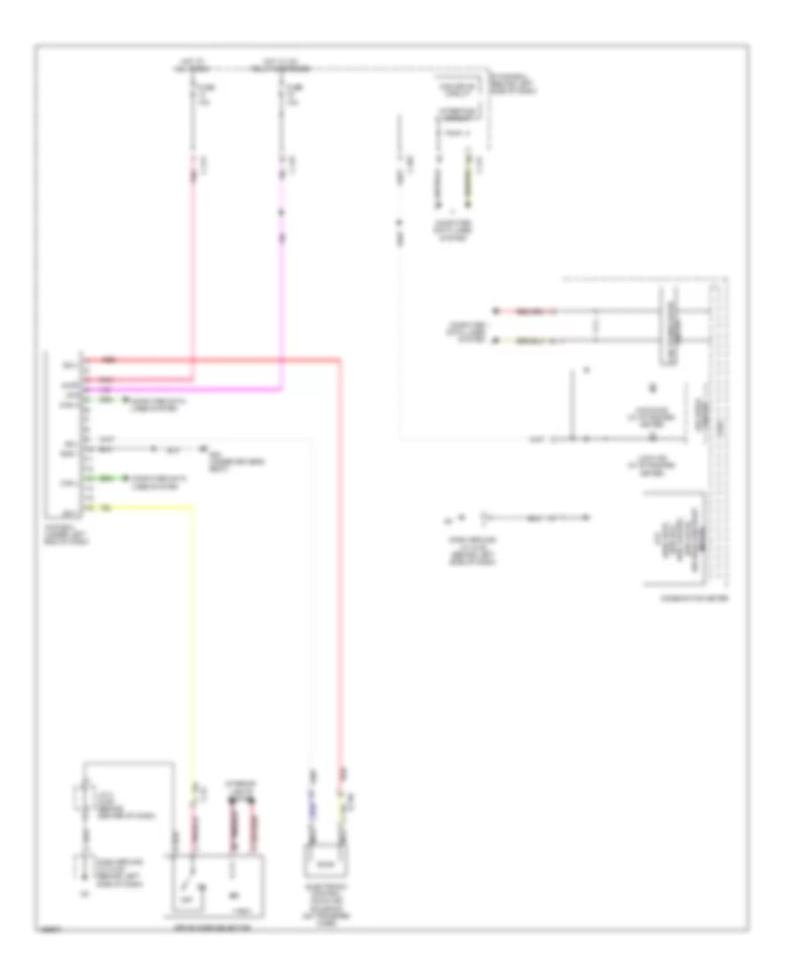
AWD Wiring Diagram for Mitsubishi Outlander SE 2014
List of elements for AWD Wiring Diagram for Mitsubishi Outlander SE 2014:
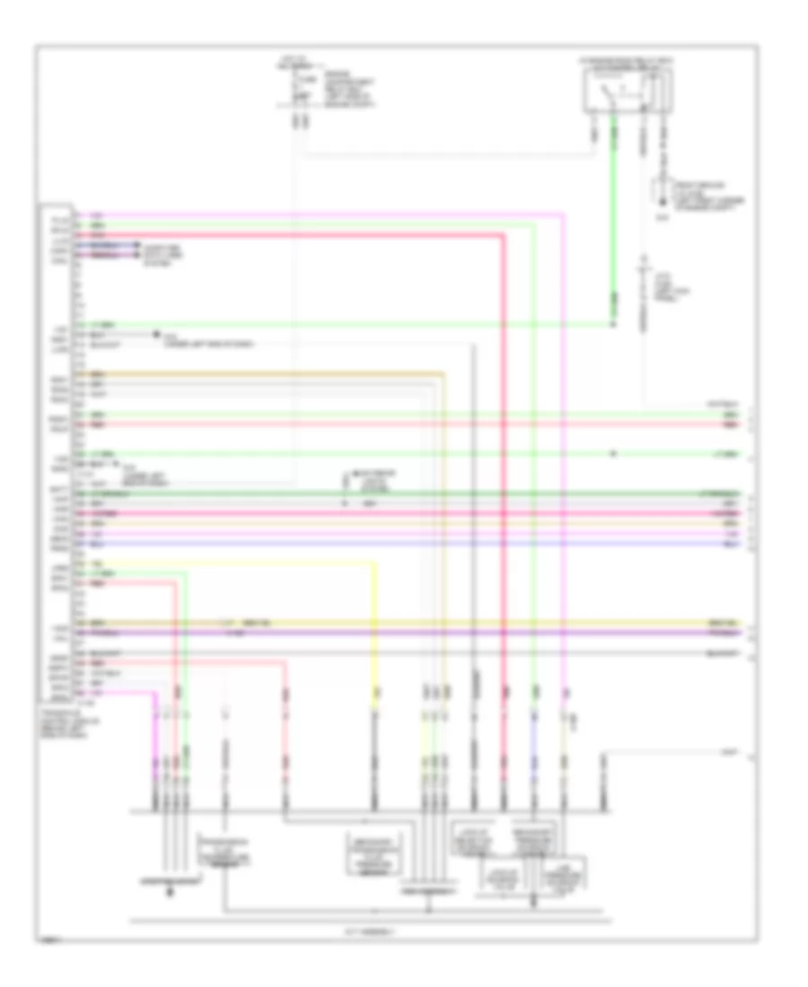
CVT Wiring Diagram (1 of 2) for Mitsubishi Outlander SE 2014
List of elements for CVT Wiring Diagram (1 of 2) for Mitsubishi Outlander SE 2014:
CVT Wiring Diagram (2 of 2) for Mitsubishi Outlander SE 2014
List of elements for CVT Wiring Diagram (2 of 2) for Mitsubishi Outlander SE 2014: