TRANSMISSION
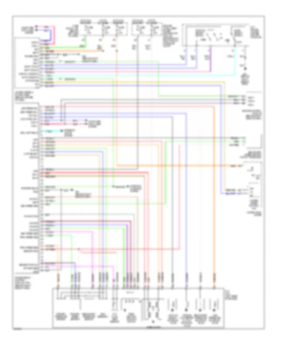
A/T Wiring Diagram for Nissan Maxima SL 2007
List of elements for A/T Wiring Diagram for Nissan Maxima SL 2007:
- At-p range
- Atf temp sen
- Auto
- Auto mode sw
- Batt
- Can-h
- Can-l
- Chip select
- Clock
- Combination meter
- Computer data lines system
- Cvt device (under center console)
- Cvt fluid temp sensor
- Cvt ind
- Cvt unit (left rear of engine)
- Data i/o
- Dwn
- Ecm
- Engine control module (behind right side of dash)
- Exterior lights system
- Fuse 10a
- Fuse 15a
- Fuse block (j/b) (behind left side of dash)
- Gnd
- Hot at all times
- Hot in on or start
- Ign
- Inh sw1
- Inh sw2
- Inh sw3
- Inh sw3 mon
- Inh sw4
- Ipdm e/r (intelligent power distribution module engine room) (right front of engine compt)
- Lck-up sel sol
- Line press sol
- Line pressure solenoid valve
- Lock-up select solenoid valve
- M57 (behind right side of dash)
- M61 (behind right side of dash)
- Man
- Manual mode sw
- Mode select switch
- Neut
- Park/ neutral position switch
- Pnk
- Position select switch
- Power gnd
- Prim press sen
- Prim speed sen
- Primary pressure sensor
- Primary speed sensor
- Red
- Rev lamp relay
- Rom assembly
- S/m a
- S/m b
- S/m c
- S/m d
- Sec press sen
- Sec press sol
- Sec speed sen
- Secondary pressure sensor
- Secondary pressure solenoid valve
- Secondary speed sensor (top of transaxle)
- Sensor gnd
- Sensor pwr (5v)
- Shift dn sw
- Shift up sw
- Starter relay
- Starting/ charging system
- Step motor
- Tcc sol
- Torque converter clutch solenoid valve
- Transmission control module (tcm) (behind right side of dash)
- Unified meter & a/c amplifier (behind center of dash)
- Unified meter control unit
- Vign
 English