TRANSMISSION
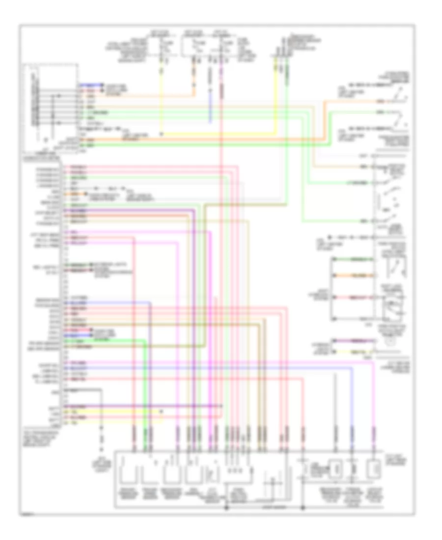
Transmission Wiring Diagram for Nissan Maxima SV 2009
List of elements for Transmission Wiring Diagram for Nissan Maxima SV 2009:
- (if equipped) paddle shifter (shift up)
- 12m
- 12p
- A/t check ind
- Atf temp sens
- Auto
- Batt
- Can-h
- Can-l
- Chip select
- Clock
- Combination meter
- Computer data lines system
- Cvt device (under center console)
- Cvt fluid temperature sensor
- Cvt unit (left rear of engine)
- D range sw
- Data i/o
- Down
- Down sw shift up sw
- E15 (left side of engine compt)
- Exterior lights system starting/charging system
- F10
- Fuse 10a
- Fuse block (j/b) (lower left side of dash)
- Gnd
- Hot at all times
- Hot in on or start
- Interior lights system
- Ipdm e/r (intelligent power distribution module engine room) (left side of engine compt)
- K-line
- L range sw
- Line pressure solenoid valve
- Liner sol
- Lock-up select solenoid valve
- M203
- M23
- M24
- M78
- M79 (left center of dash)
- Man
- Mode select switch
- N range sw
- On/off sol
- P range sw
- Paddle shifter (shift down) (if equipped)
- Park position switch (intelligent key system)
- Park position switch (shift selector)
- Park/ neutral position switch
- Pl liner sol
- Pnk
- Position select switch
- Pri oil pree
- Pri spd sensor
- Primary pressure sensor
- Primary speed sensor
- Pwr source
- R range sw
- Red
- Rev lamp rly
- Rom assembly
- S/m-a
- S/m-b
- S/m-c
- S/m-d
- Sec liner sol
- Sec oil pree
- Sec spd sensor
- Secondary pressure sensor
- Secondary pressure solenoid valve
- Secondary speed sensor (top of transaxle)
- Sens gnd
- Sensor gnd
- Shift
- Shift interlock system
- Shift lock solenoid
- Spd sens
- St rly
- Step motor
- Tcm (transmission control module) (left front of engine compt)
- Torque converter clutch solenoid valve
- Unified meter control unit (w/ information display)
- Vign
 English