TRANSMISSION
A/T Wiring Diagram for Nissan Murano SE 2004

List of elements for A/T Wiring Diagram for Nissan Murano SE 2004:
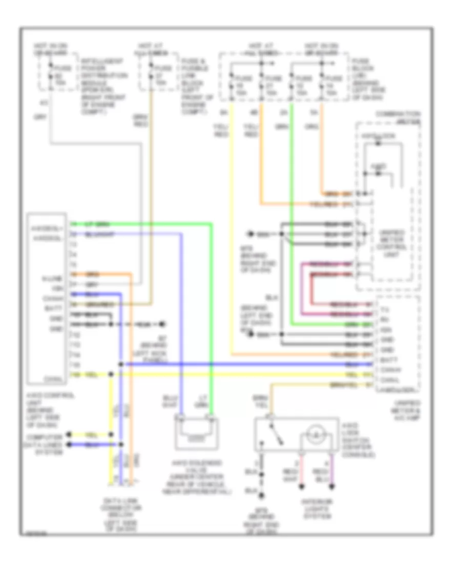
AWD Wiring Diagram for Nissan Murano SE 2004
List of elements for AWD Wiring Diagram for Nissan Murano SE 2004:
 English
A/T Wiring Diagram for Nissan Murano SE 2004
List of elements for A/T Wiring Diagram for Nissan Murano SE 2004:
AWD Wiring Diagram for Nissan Murano SE 2004
List of elements for AWD Wiring Diagram for Nissan Murano SE 2004: