TRANSMISSION
Transmission Wiring Diagram (1 of 2) for Nissan NV1500 SV 2013

List of elements for Transmission Wiring Diagram (1 of 2) for Nissan NV1500 SV 2013:
- A/t assembly (bottom of transmission)
- A/t fluid temperature sensor
- Atf sens
- C1 (vin)
- C2 (vout)
- C3 (gnd)
- Can-h
- Can-l
- Common
- Computer data lines lines system
- Computer data lines system
- Control module (tcm)
- Direct clutch solenoid valve
- E9 (right rear of engine compt)
- Exterior lights system
- F14 e5
- F502
- F503
- F504
- F505
- F506
- Front brake solenoid valve
- Gnd-1
- Gnd-2
- High & low reverse clutch solenoid valve
- Input clutch solenoid valve
- Input speed sensor 1
- Input speed sensor 2
- K-line
- Line pressure solenoid valve
- Linear sol
- Low coast brake solenoid valve
- Oil press switch 2
- Output speed sen
- Output speed sen gnd
- Output speed sen power
- Output speed sensor
- Pnk
- Pressure switch 2 (lc/b)
- Red
- Rev lamp rly
- Sens 1
- Sens 2
- Start-rly
- Starting/ charging system
- Supp-1
- Supp-2
- Torque converter clutch solenoid valve
- Tr-sw1
- Tr-sw2
- Tr-sw3
- Tr-sw4
- Transmission
- Transmission range switch
- Vign
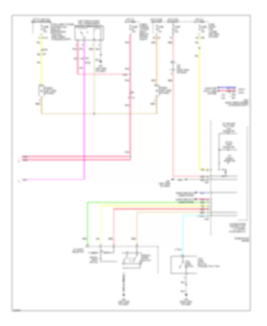
Transmission Wiring Diagram (2 of 2) for Nissan NV1500 SV 2013
List of elements for Transmission Wiring Diagram (2 of 2) for Nissan NV1500 SV 2013:
- (left side of dash) tcm (transmission control module relay)
- (w/ trailer tow 7 pin) tow indicator
- 4.0l
- 4q m39
- 5.6l
- A/t check indicator
- A/t oil temp indicator
- A/t shift selector
- Can-h
- Can-l
- Combination meter
- Computer data lines system
- Diode 1 (left side of dash)
- Diode 2 (left side of dash)
- Dn(-)
- E119
- E152
- E16
- E77
- Ecm (right rear corner of engine compt)
- F14
- Fuse & fusible link box (right rear of engine compt)
- Fuse 10a
- Fuse block (j/b) (lower left end of dash)
- Hot at all times
- Hot in acc or start
- Hot in on or start
- Hot w/ ignition relay energized
- Intelligent power distribution module engine room (ipdm e/r) (right rear of engine compt)
- J/c m04 (right end of dash)
- M23
- M24
- M3 2n
- M31 19g
- M31 2g
- M57 (left end of dash)
- M61 (left side of dash)
- M79 (right end of dash)
- Manual mode switch
- Manual shift switch
- Pnk
- Red
- Tow mode switch
- Tow mode switch (trailer tow 7 pin)
- Unified meter control unit (w/ inform- ation display)
- Up(+)