TRANSMISSION
Transmission Wiring Diagram for Nissan NV200 Taxi 2014
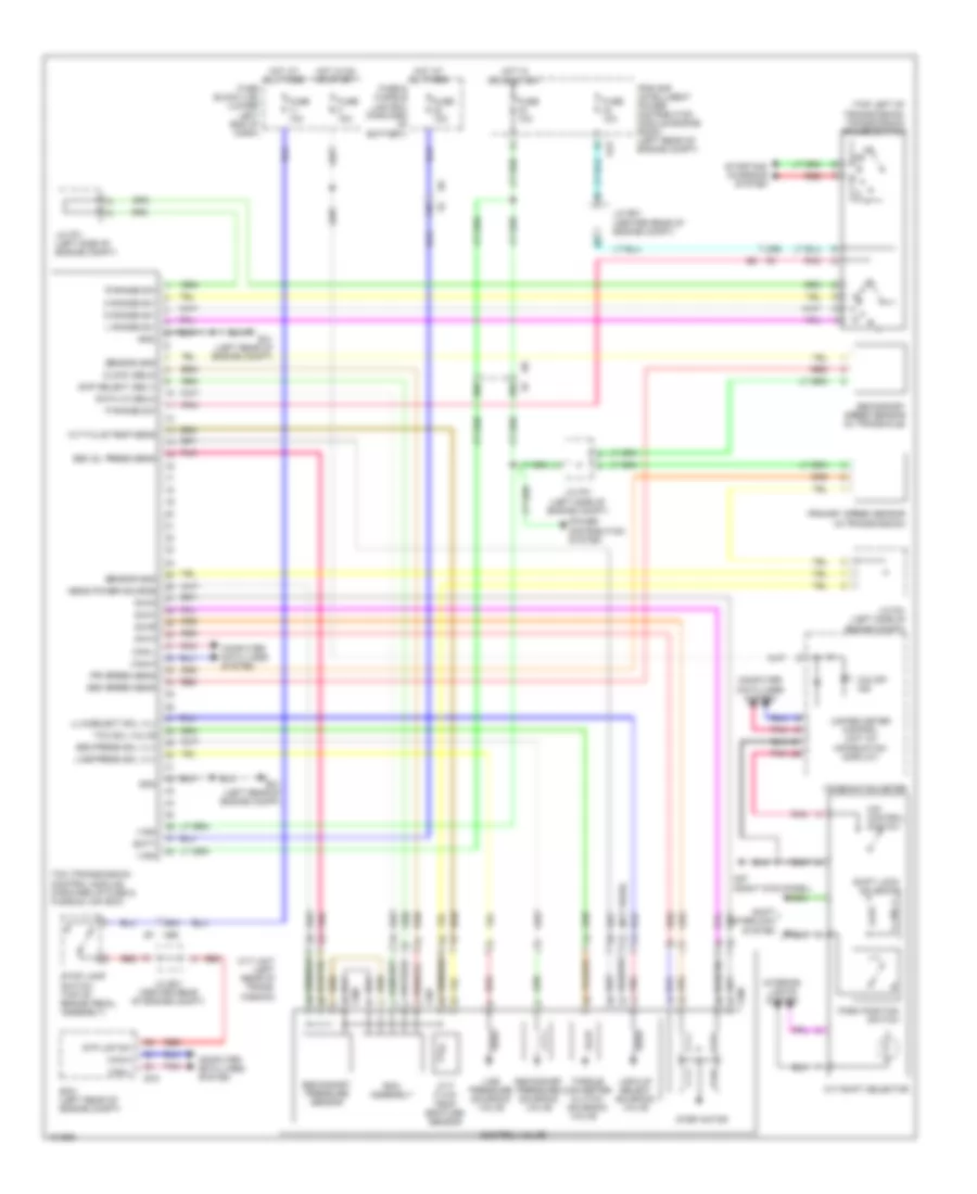
List of elements for Transmission Wiring Diagram for Nissan NV200 Taxi 2014:
- (not used)
- (top left of transmission) transmission range switch
- 15b
- 20b
- 38b
- 39b
- 92a
- Batt
- Can-h
- Can-l
- Chip select (sel1)
- Clock (sel2)
- Combination meter
- Computer data lines system
- Control valve
- Cvt fluid temp sens
- Cvt fluid temp- erature sensor
- Cvt shift selector
- Cvt unit (left rear of trans- mission)
- D range sw
- Data i/o (sel3)
- E16
- E41 (left rear of engine compt)
- E43
- Ecm (left rear of engine compt)
- F207
- F208
- Fuse & fusible link box (forward of battery)
- Fuse 10a
- Fuse block (j/b) (lower left end of dash)
- Gnd
- Hot at all times
- Hot in on or start
- Interior lights system
- Ipdm e/r (intelligent power distribution module engine room) (left rear of engine compt)
- J/c e01 (center rear of engine compt)
- J/c f01 (left side of engine compt)
- L range sw
- Line press sol vlv
- Line pressure solenoid valve
- Lock-up select solenoid valve
- Lu & select sol vlv
- M57 (right kick panel)
- M69 e7
- N range sw
- O/d control switch
- O/d off ind
- P range sw
- Park position switch
- Pnk
- Power distribution system
- Pri speed sens
- Primary speed sensor (in transmission)
- R range sw
- Red
- Rom assembly
- S/m-a
- S/m-b
- S/m-c
- S/m-d
- Sec oil press sens
- Sec press sol vlv
- Sec speed sens
- Secondary pressure sensor
- Secondary pressure solenoid valve
- Secondary speed sensor (in transaxle)
- Sens power source
- Sensor gnd
- Shift interlock system
- Shift lock solenoid
- Starting/ charging system
- Step motor
- Stop lamp switch (top of brake pedal assembly)
- Stp lmp sw
- Tcc sol valve
- Tcm (transmission control module) (forward of fuse & fusible link box)
- Torque converter clutch solenoid valve
- Unified meter control unit (w/ information display)
- Vign
 English