TRANSMISSION
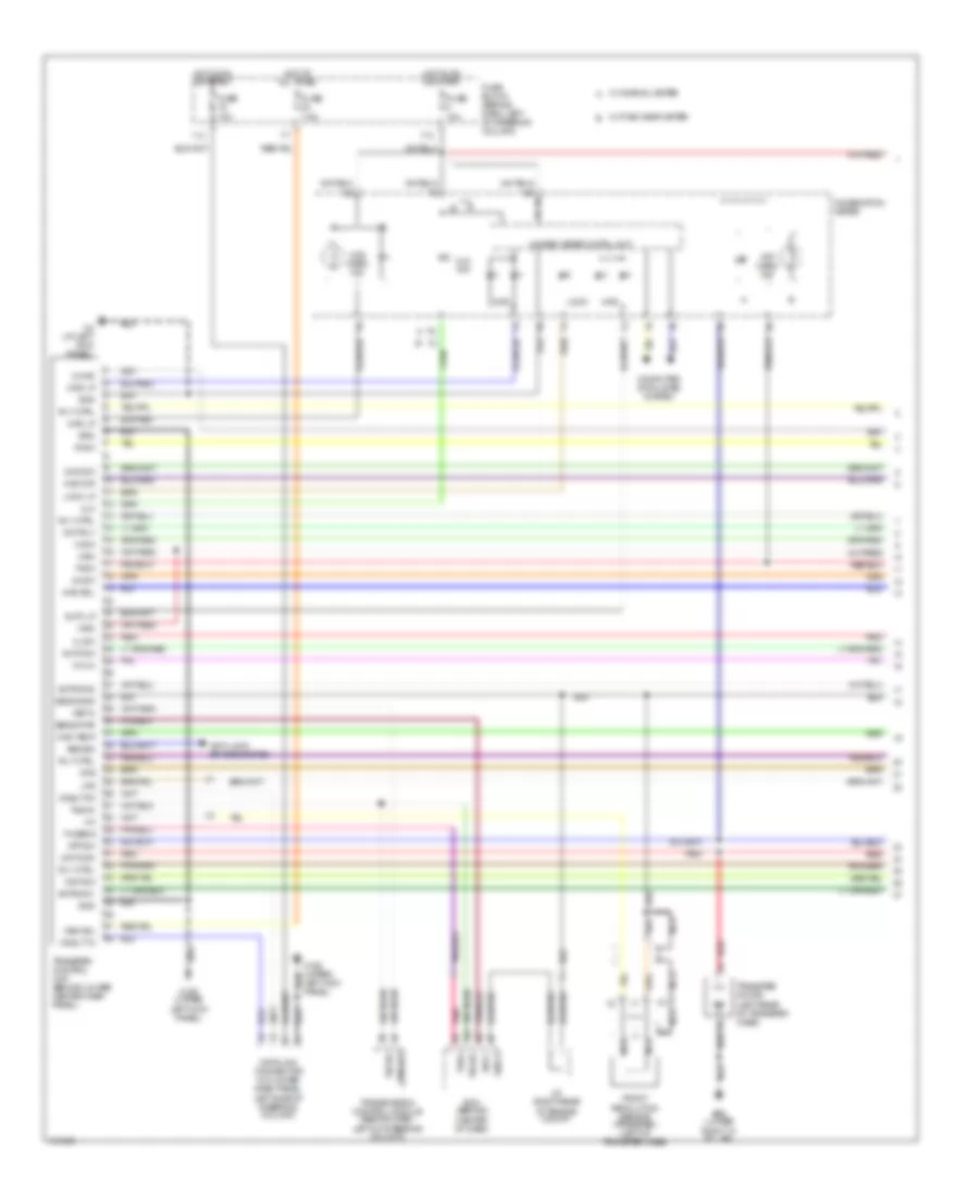
4WD Wiring Diagram, with Stability Assist (1 of 2) for Nissan Pathfinder SE 2004

List of elements for 4WD Wiring Diagram, with Stability Assist (1 of 2) for Nissan Pathfinder SE 2004:
- 11u
- 17u
- 2-4wd
- 2wd
- 2wd lp
- 2wd sw
- 4h sw
- 4l sw
- 4lo
- 4lo ind
- 4wd
- 4wd d/r
- 4wd lp
- 4wd sol
- 4wd temp
- 4wd warn ind
- Actr sw1
- Actr sw2
- Atp
- Atp sw
- Atp warn ind
- Auto lp
- Auto sw
- Avcc
- B55 (lower right "a" pillar)
- Can h
- Can l
- Center of dash)
- Cnslt rx
- Cnslt tx
- Combination meter
- Computer data lines system
- Cps
- Data link connector (on lower dash panel, left side of steering column)
- Ecm (behind
- Front revolution sensor (transfer) (left of transfer case)
- Fuse 10a
- Fuse 7.5a
- Fuse block (behind dash, left of steering column)
- Gnd
- Gnd-a
- Hot at all times
- Hot in on or start
- J/c (right rear
- Lock
- Lock lp
- Lps
- M158 (upper left kick panel)
- M4 (at left kick panel)
- Mem b/u
- Mot/mon
- Mot/rly
- N-4lo
- Nca
- Of engine compt)
- Red
- Rly ctrl
- Sens gnd
- Sens pwr
- Transfer control unit (behind lower center dash panel)
- Transfer motor (left rear of transfer case)
- Unified meter cntrl unit
- Vign
- W/ fine visor meter
- W/ normal meter
- Wait sw
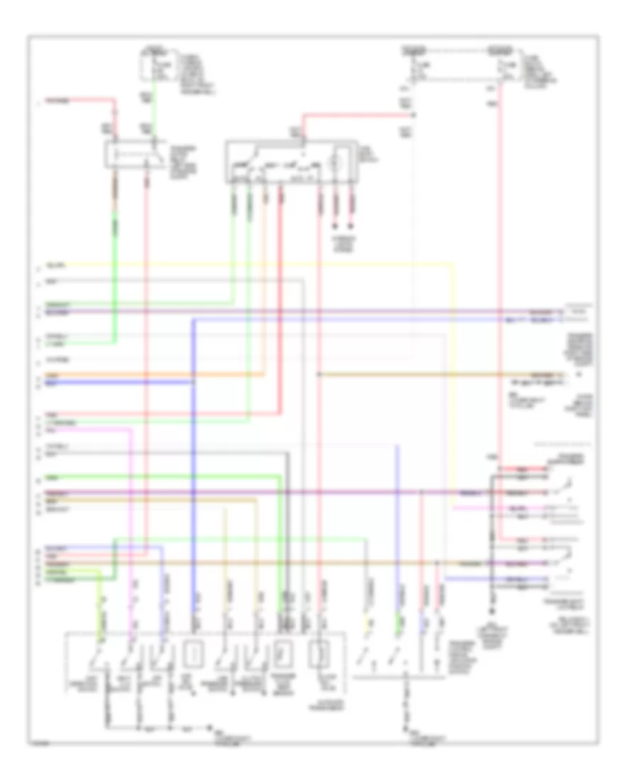
4WD Wiring Diagram, with Stability Assist (2 of 2) for Nissan Pathfinder SE 2004
List of elements for 4WD Wiring Diagram, with Stability Assist (2 of 2) for Nissan Pathfinder SE 2004:
- 2-4wd sol valve
- 24u
- 2wd
- 48u
- 4lo
- 4wd shift switch
- 4wd sol valve
- Atp switch
- Auto
- Automatic transmission
- B55 (lower right "a" pillar)
- Clutch pressure switch
- Diode (behind right kick panel)
- E13 (left front corner of engine compt)
- Fuse & fusible link box (in relay box 2, on right front fenderwell)
- Fuse 10a
- Fuse 20a
- Fuse block (behind dash, left of steering column)
- Hot at all times
- Hot in on or start
- Interior lights system
- Line pressure switch
- Nca
- Neut 4 lo switch
- Red
- Relay box 1 (on left front fenderwell)
- Transfer control device (actuator position switch)
- Transfer dropping resistor (right side of engine compt)
- Transfer fluid temp sensor
- Transfer motor relay (left side of engine compt)
- Transfer shift hi relay
- Transfer shift low relay
- Wait detection switch
4WD Wiring Diagram, without Stability Assist (1 of 2) for Nissan Pathfinder SE 2004
List of elements for 4WD Wiring Diagram, without Stability Assist (1 of 2) for Nissan Pathfinder SE 2004:
- 11u
- 17u
- 2-4wd
- 2wd
- 2wd lp
- 2wd sw
- 4h sw
- 4l sw
- 4lo
- 4lo ind
- 4wd
- 4wd d/r
- 4wd lp
- 4wd sol
- 4wd temp
- 4wd warn ind
- Abs sig
- Actr sw1
- Actr sw2
- Anti-lock brakes system
- Atp sw
- Atp warn ind
- Auto lp
- Auto sw
- Avcc
- B55 (lower right "a" pillar)
- Cnslt rx
- Cnslt tx
- Combination meter
- Computer data lines system
- Cps
- Data link connector (on lower dash panel, left side of steering column)
- Ecm (behind center of dash)
- Front revolution sensor (transfer) (left of transfer case)
- Fuse 10a
- Fuse 7.5a
- Fuse block (behind dash, left of steering column)
- Gnd
- Gnd-a
- Hot at all times
- Hot in on or start
- J/c (right rear
- Lock
- Lock lp
- Lps
- M158 (upper left kick panel)
- M4 (at left kick panel)
- Mem b/u
- Mot/mon
- Mot/rly
- N-4lo
- N-sw
- Nca
- Of engine compt)
- P-sw
- Pnk
- R-sw
- Red
- Rly ctrl
- Sens gnd
- Sens pwr
- Tacho
- Th sens
- Transfer control unit (behind lower center dash panel)
- Transfer motor (left rear of transfer case)
- Transmission control module (behind dash, left of steering column)
- Tvoo
- Unified meter cntrl unit
- Vign
- Vsp in
- Vspout
- W/ fine visor meter
- W/ normal meter
- Wait sw
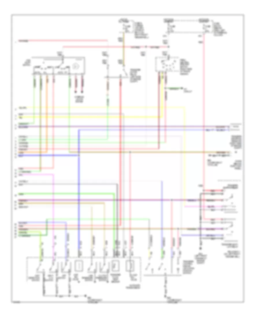
4WD Wiring Diagram, without Stability Assist (2 of 2) for Nissan Pathfinder SE 2004
List of elements for 4WD Wiring Diagram, without Stability Assist (2 of 2) for Nissan Pathfinder SE 2004:
- 2-4wd sol valve
- 24u
- 2wd
- 48u
- 4lo
- 4wd shift switch
- 4wd sol valve
- A/t circuit
- Atp switch
- Auto
- Automatic transmission
- B55 (lower right "a" pillar)
- Clutch pressure switch
- Diode (behind right kick panel)
- E13 (left front corner of engine compt)
- Fuse & fusible link box (in relay box 2, on right front fenderwell)
- Fuse 10a
- Fuse 20a
- Fuse block (behind dash, left of steering column)
- Hot at all times
- Hot in on or start
- Interior lights system
- Line pressure switch
- Nca
- Neut 4 lo switch
- Park/ neutral position switch (right side of trans- mission)
- Red
- Relay box 1 (on left front fenderwell)
- Transfer control device (actuator position switch)
- Transfer dropping resistor (right side of engine compt)
- Transfer fluid temp sensor
- Transfer motor relay (left side of engine compt)
- Transfer shift hi relay
- Transfer shift low relay
- Wait detection switch
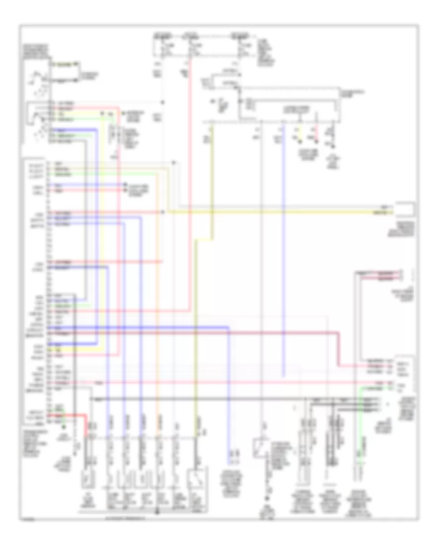
A/T Wiring Diagram for Nissan Pathfinder SE 2004
List of elements for A/T Wiring Diagram for Nissan Pathfinder SE 2004:
- (behind center of dash)
- (right side of transmission) park/neutral position switch
- 1-sw
- 17u
- 2-sw
- 24u
- 4wd circuit
- A/t device (overdrive control switch) (base of selector lever)
- A/t fluid temp ind
- A/t fluid temp sensor
- A/t fluid temp switch (4wd)
- Automatic transaxle
- Avcc
- B55 (lower right "a" pillar)
- B64
- Can-h
- Can-l
- Combination meter
- Computer data lines system
- D-sw
- Data in
- Data link connector (on lower dash panel, left of steering column)
- Data out
- Diode (behind left side of dash)
- Dropping resistor (right side of engine compt)
- Engine control module
- Engine coolant temperature sensor (rear of engine, on water outlet)
- Exterior lights system
- Fld temp
- Fuse 10a
- Fuse 7.5a
- Fuse block (behind dash, left of steering column)
- Gnd
- Gnd-a
- Hot at all times
- Hot in on or start
- J/c (behind left side of dash)
- J/c (right rear of engine compt)
- Line press sol valve
- Lu duty
- M158 (upper left kick panel)
- M4 (at left kick panel)
- Mem b/u
- Nca
- O/d off ind
- Ov r/c
- Over- run clutch sol
- P/n-sw
- Pl duty
- Pnk
- R-sw
- Rear revolution sensor (right side of trans- mission)
- Red
- Sens gnd
- Sens pwr
- Shift a
- Shift b
- Shift sol valve a
- Shift sol valve b
- Starting system
- Tacho
- Tcc sol valve
- Th sens
- Transmission control module (behind dash, left of steering column)
- Tss
- Turbine revolution sensor (top front of trans- mission case)
- Tv00
- Unified meter control unit
- V ign
- Vsp out
- Vsp-2
- Vsp1