TRANSMISSION
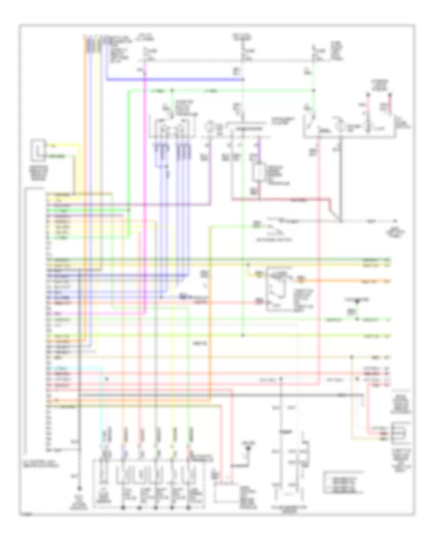
Transmission Wiring Diagram for Nissan Quest GXE 1994
List of elements for Transmission Wiring Diagram for Nissan Quest GXE 1994:
- A/t control unit (behind glove box)
- A/t fluid temp. sensor
- A/t mode switch
- All times
- Ascd control unit (behind center console)
- Automatic transaxle
- Backup lights
- Closed throttle
- Cruise
- Data link connector (for consult) (below left side of i/p)
- Dropping resistor (rear of engine)
- Eccs control module (behind glove box)
- Fuse block (left kick panel)
- Fuse m 10a
- Fuse u 10a
- Fuse z 10a
- G131 (on intake manifold)
- G200 (left kick panel)
- Hot at
- Hot in on or start
- Illum.
- Ind.
- Inhibitor switch (top of transaxle)
- Instrument cluster
- Interior lights system
- Line press. sol. valve
- Nca
- O.d. off ind.
- Od cancel switch
- Over- run clutch sol.
- Pnk
- Power ind.
- Pulse generator sensor
- Pwr
- Red
- Shift sol. valve a
- Shift sol. valve b
- Speedometer
- Tachometer
- Tcc sol. valve
- Throttle position sensor (on throttle body)
- Throttle position switch (on throttle body)
- Vehicle speed sensor (on transaxle)
- Wot
 English