TRANSMISSION
A/T Wiring Diagram (1 of 2) for Porsche Cayman 2007

List of elements for A/T Wiring Diagram (1 of 2) for Porsche Cayman 2007:
- (left side of engine compt) gp9
- (pins 56-81 not used)
- A/d converter gnd
- Atf temp sensor
- Atf temperature sensor
- B3 can hi
- Can hi
- Can lo
- Can term resistor h
- Can term resistor l
- Diagnosis plug socket (below left side of dash)
- Drive sp
- Drive sp gnd
- Drive sp shdl
- Drive speed sensor
- Eds pressure controller
- Egn sp turbine gnd
- Electronic gnd
- Eng sp turbine shld
- Fuse f5 15a
- Fuse f8 7.5a
- Fuse holder b (under left side of dash, at left kick panel)
- Fuse holder c (under left side of dash, at left kick panel)
- Hot at all times
- Hot w/ term 15 relay energized
- K lead diagnosis
- Magnet shift lock
- Manual prog shift
- Mfi-di control unit (left side of rear luggage compt)
- Nca
- Pressure ctlr 1
- Pressure ctlr 2
- Pressure ctlr 3
- Pressure ctlr 4
- Pressure ctrl solenoid valve
- Pwr gnd
- Solenoid valve 1
- Solenoid valve 2
- Solenoid valve 3
- Sw lifting
- Sw lifting w1
- Sw lifting w2
- Sw lifting w3
- Term 15
- Term 30
- Transmission control
- Transmission control unit (on gear box)
- Turbine eng sp
- Turbine sensor
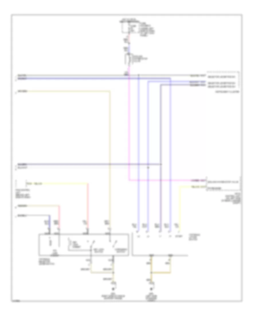
A/T Wiring Diagram (2 of 2) for Porsche Cayman 2007
List of elements for A/T Wiring Diagram (2 of 2) for Porsche Cayman 2007:
- (under left side of dash, at left kick panel)
- A12
- A13
- A14
- A16
- C13
- Cooling water stop valve
- D40
- Fuse f5 25a
- Fuse holder d
- Gnd
- Gp5 (right side of middle support frame)
- Gp9 (left side of engine compt)
- Hot w/ mfi-di relay energized
- Instrument cluster
- Key lock magnet
- Key lock switch
- M-program switch
- Mfi-di control unit (on left side of rear luggage compt)
- Nca
- P/n lock magnet
- P/n release
- Pas control unit (behind left side of dash)
- Selector lever pos sw
- Start
- Tiptronic lifting switch
- Tiptronic selector lever switch