TRANSMISSION
2.2L VIN D
2.2L VIN D, A/T Wiring Diagram for Saturn Vue 2004

List of elements for 2.2L VIN D, A/T Wiring Diagram for Saturn Vue 2004:
- (eng harn, near automatic transmission c1 connector)
- (late prod only)
- (pin 32-43 not used)
- A12 can lo
- Automatic transaxle
- B12 can hi
- Backup fuse 10a
- Battery
- Body control module (below front of center console)
- Brake fuse 15a
- Can hi
- Can hi (bcm)
- Can hi (ecm)
- Can lo
- Can lo (bcm)
- Can lo (ecm)
- D10
- Datalink connector (lower left side of dash)
- Dlc
- Ecm/tcm fuse 10a
- Electronic traction control module (near left front shock tower)
- Engine control module (on intake manifold, under ignition coil housing)
- Exterior lights system
- G105 (at left rear of engine)
- Ground
- Hot at all times
- Hot in run or start
- Ignition
- Ignition 1
- Input shaft speed sensor
- Iss diode
- Iss hi
- Iss lo
- Line pcs hi
- Line pcs lo
- Line pressure control solenoid
- Nca
- Oss hi
- Oss lo
- Output shaft speed sensor
- Park/neutral position switch assembly
- Pnk
- Pres sens gnd
- Pres sens sig
- Pressure sensor
- Pwr train fuse 10a
- Ratio a1
- Ratio a2
- Ratio b1
- Ratio b2
- Ratio control motor
- Red c
- Red g
- S100
- S103
- S104
- S304 (in body harn, near cross car breakout)
- Sens 5v ref
- Serial data
- Stop lamps
- Stoplamp switch (on brake pedal bracket)
- Tan
- Tcc enable solenoid
- Tcc hi enable
- Tcc lo enable
- Tcc pc hi
- Tcc pc lo
- Tcc pressure control solenoid
- Tft hi
- Tft lo
- Tr a
- Tr b
- Tr c
- Tr p
- Transaxle control module (left side of engine compt)
- Transaxle fluid temperature sensor
- Underhood fuse block (left side of engine compt)
- W/ abs
- W/o abs
2.2L VIN F
2.2L VIN F, A/T Wiring Diagram for Saturn Vue 2004
List of elements for 2.2L VIN F, A/T Wiring Diagram for Saturn Vue 2004:
- (eng harn, near automatic transmission c1 connector)
- (late prod only)
- (pin 32-43 not used)
- A12 can lo
- Automatic transaxle
- B12 can hi
- Backup fuse 10a
- Battery
- Body control module (below front of center console)
- Brake fuse 15a
- Can hi
- Can hi (bcm)
- Can hi (ecm)
- Can lo
- Can lo (bcm)
- Can lo (ecm)
- D10
- Datalink connector (lower left side of dash)
- Dlc
- Ecm/tcm fuse 10a
- Electronic traction control module (near left front shock tower)
- Engine control module (on intake manifold, under ignition coil housing)
- Exterior lights system
- G105 (at left rear of engine)
- Ground
- Hot at all times
- Hot in run or start
- Ignition
- Ignition 1
- Input shaft speed sensor
- Iss diode
- Iss hi
- Iss lo
- Line pcs hi
- Line pcs lo
- Line pressure control solenoid
- Nca
- Oss hi
- Oss lo
- Output shaft speed sensor
- Park/neutral position switch assembly
- Pnk
- Pres sens gnd
- Pres sens sig
- Pressure sensor
- Pwr train fuse 10a
- Ratio a1
- Ratio a2
- Ratio b1
- Ratio b2
- Ratio control motor
- Red c
- Red g
- S100
- S103
- S104
- S304 (in body harn, near cross car breakout)
- Sens 5v ref
- Serial data
- Stop lamps
- Stoplamp switch (on brake pedal bracket)
- Tan
- Tcc enable solenoid
- Tcc hi enable
- Tcc lo enable
- Tcc pc hi
- Tcc pc lo
- Tcc pressure control solenoid
- Tft hi
- Tft lo
- Tr a
- Tr b
- Tr c
- Tr p
- Transaxle control module (left side of engine compt)
- Transaxle fluid temperature sensor
- Underhood fuse block (left side of engine compt)
- W/ abs
- W/o abs
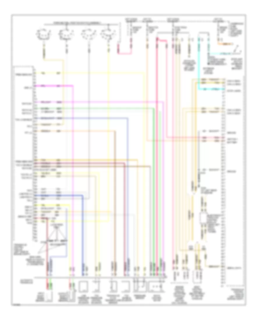
3.5L VIN 4
3.5L VIN 4, A/T Wiring Diagram (1 of 2) for Saturn Vue 2004
List of elements for 3.5L VIN 4, A/T Wiring Diagram (1 of 2) for Saturn Vue 2004:
- (rear of engine, on throttle body) throttle actuator control module
- 3rd clutch press sw sig
- 3rd clutch pressure switch (at rear of transmission)
- 4th clutch press sw sig
- 4th clutch pressure switch (at rear of transmission)
- 5 vol ref
- 5 volt ref
- A/t drive sig
- A/t drive sw
- A/t forward sig
- A/t iss hi sig
- A/t lo sig
- A/t neutral sw
- A/t park sig
- A/t reverse sig
- Automatic transmission
- Batt positive voltage
- Brake fuse 15a
- Can hi
- Can lo
- Clutch press sol 1 hi
- Clutch press sol 1 lo
- Clutch press sol 2 hi
- Clutch press sol 2 lo
- Clutch pressure control solenoid valves (in automatic transmission)
- Computer data lines system
- Data link connector (lower left side of dash)
- Ecm/tcm fuse 10a
- Ect fuse 15a
- Ect sen sig
- Engine controls system
- Engine coolant temperature sensor (rear of engine)
- Etc ctrl
- Etc sig
- Exterior lights and cruise control system
- F10
- G101 (rear of eng)
- G107 (left rear of engine)
- G107 (rear of engine)
- Gnd
- Hot at all times
- Hot in run or start
- Ign 1
- Ign 1 voltage
- Key serial data
- Lo ref
- Minhibit
- Mot inhibit
- Oss hi sig
- Powertrain control module (in eng compr, mounted near right strut tower)
- Pwr train fuse 10a
- Red
- S124 (eng harn, in egr valve circuit)
- S129
- Shift sol valve 1 hi
- Shift sol valve 2 hi
- Shift sol valve 3 hi
- Shift solenoid valves
- Splice pack sp114 (right side of engine)
- Stop lamp switch (on brake pedal bracket)
- Stp lp sw
- Tan
- Tcc enable sol hi
- Tcc pc sol hi
- Tcc pc sol lo
- Tft sen sig
- Torque converter clutch enable solenoid valve
- Underhood fuse block (left side of engine compt)
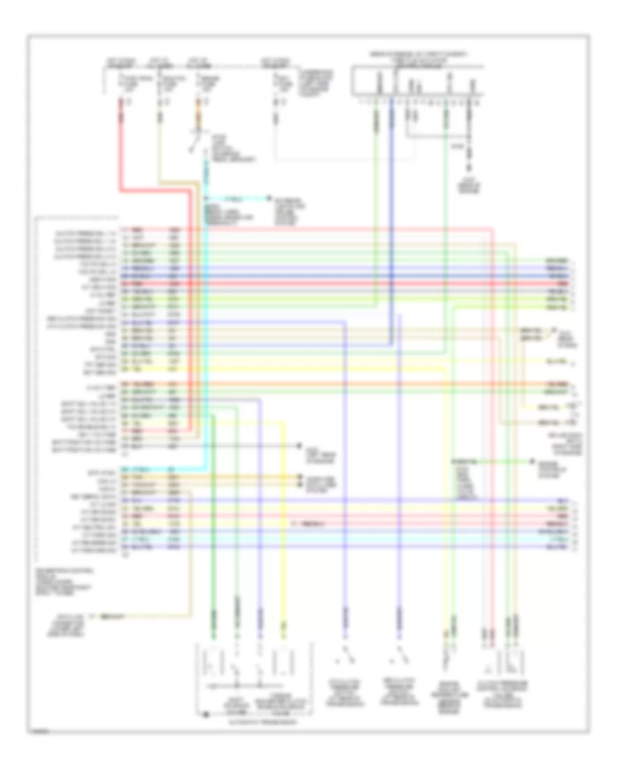
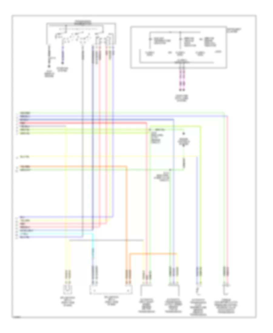
3.5L VIN 4, A/T Wiring Diagram (2 of 2) for Saturn Vue 2004
List of elements for 3.5L VIN 4, A/T Wiring Diagram (2 of 2) for Saturn Vue 2004:
- (eng harn, in egr valve circuit)
- Automatic input shaft speed sensor (on top transmission)
- Automatic transmission fluid temperature sensor (rear of transmission)
- Automatic transmission output speed sensor (top of transmission)
- Class 2 (pcm)
- Class 2 serial data
- Computer data lines system
- Coolant temperature indicator
- Engine controls system
- G107 (rear of engine)
- Ign
- Instrument cluster
- Logig
- Pressure control solenoid valve (in automatic transmission)
- Red
- S112
- S115
- S123 (eng harn, in tft sensor circuit)
- Service engine soon (mil) indicator
- Service vehicle soon indicator
- Splice pack sp113 (right side of eng)
- Splice pack sp114 (right side of eng)
- Starting system
- Torque converter clutch
- Transmission range switch