TRANSMISSION
Transmission Wiring Diagram (1 of 2) for Subaru B9 Tribeca Limited 2006

List of elements for Transmission Wiring Diagram (1 of 2) for Subaru B9 Tribeca Limited 2006:
- (behind left center of dash) op connector
- (behind left side of dash) p-vign relay
- A/t control
- B152
- B186
- B52
- B54
- B55
- Back-up light relay (behind left side of dash)
- Control valve assy
- Data link connector (under left side of dash)
- Fuse & relay box (f/b) (behind left end of dash)
- Fuse 10a
- Fuse 15a
- Fuse 7.5a
- Gb-4 (behind left kick panel)
- Hot at all times
- Hot in on or acc
- Hot in on or start
- I126
- I127
- Joint connector (behind left side of dash)
- Main fuse box (m/b) (left side of engine compt)
- Nca
- Pnk
- Rear wheel speed sensor
- Red
- Stop light switch (on brake pedal bracket)
- Torque converter turbine speed sensor 1 (left front of transmission)
- Transmission control module (tcm) (behind left side of dash)
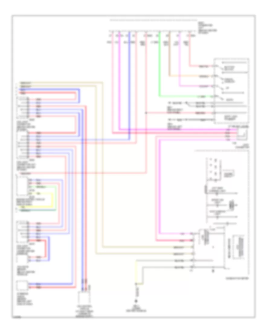
Transmission Wiring Diagram (2 of 2) for Subaru B9 Tribeca Limited 2006
List of elements for Transmission Wiring Diagram (2 of 2) for Subaru B9 Tribeca Limited 2006:
- (range position/ lcd
- At select lever
- Atf temp warning light
- Awd warning light
- B135
- B136
- B280
- B281
- B310
- B352
- B355
- B416
- Body integrated unit (behind center of dash)
- Buttion switch
- Can joint connector (behind center of dash)
- Can joint connector (int) (behind center of dash)
- Can joint connector (under center console)
- Can transceiver & receiver
- Combination meter
- Dimmer circuit
- Down
- Driver
- Engine control module (behind right side of dash)
- Gb-11 (under center console)
- Gb-4 (behind left kick panel)
- Gb-7 (behind right kick panel)
- Gear position)
- I/f
- I10
- I128
- I84
- Joint connector
- Manual mode sw
- Micro computer
- Pnk
- Red
- Shift lock solenoid
- Sport ind light
- Steering angle sensor (behind left side of dash)
- Vdc control module (at right rear corner of engine compt)
- Yaw rate sensor (below center console)