TRANSMISSION
3 Speed A/T & M/T Wiring Diagram, with Cruise Control for Suzuki Sidekick JLX 1995

List of elements for 3 Speed A/T & M/T Wiring Diagram, with Cruise Control for Suzuki Sidekick JLX 1995:
- (16 valve)
- (8 valve)
- (not used)
- (right side of engine compt, on fusible link box)
- E33
- E34
- Engine control module (under left side of dash)
- Fuse 15a
- Fuse block
- G200 (left kick panel)
- G203 (right kick panel)
- Hot at all times
- Hot in on & start
- Main relay (under left side of dash)
- Main relay control
- Oil pressure switch
- Stoplamp switch (above brake pedal)
- Tcc cancel relay
- Tcc relay control
- Torque converter clutch (tcc) relay (right side of engine compt, on fusible link box)
- Torque converter clutch (tcc) solenoid
- Transmission
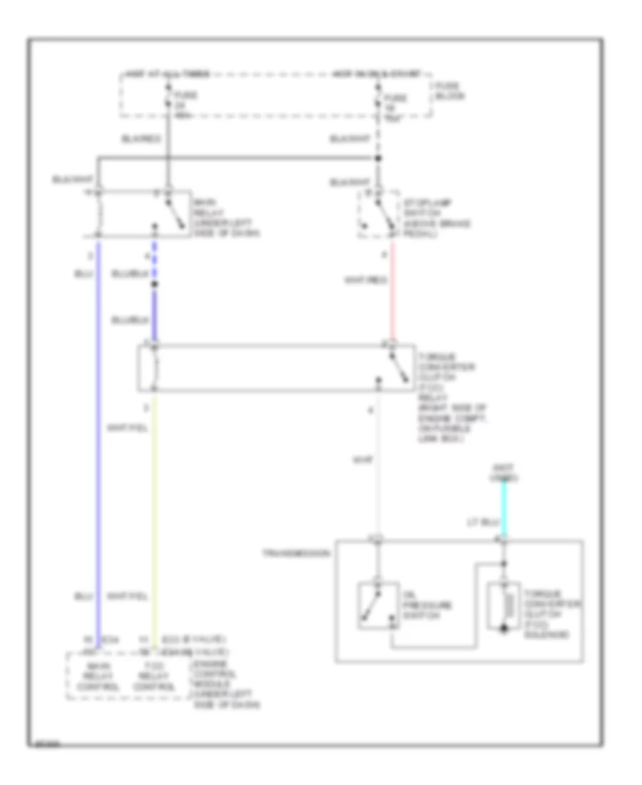
3 Speed A/T Wiring Diagram, without Cruise Control for Suzuki Sidekick JLX 1995
List of elements for 3 Speed A/T Wiring Diagram, without Cruise Control for Suzuki Sidekick JLX 1995:
- (16 valve)
- (8 valve)
- (not used)
- E33
- E34
- Engine control module (under left side of dash)
- Fuse 15a
- Fuse block
- Hot at all times
- Hot in on & start
- Main relay (under left side of dash)
- Main relay control
- Oil pressure switch
- Stoplamp switch (above brake pedal)
- Tcc relay control
- Torque converter clutch (tcc) relay (right side of engine compt, on fusible link box)
- Torque converter clutch (tcc) solenoid
- Transmission
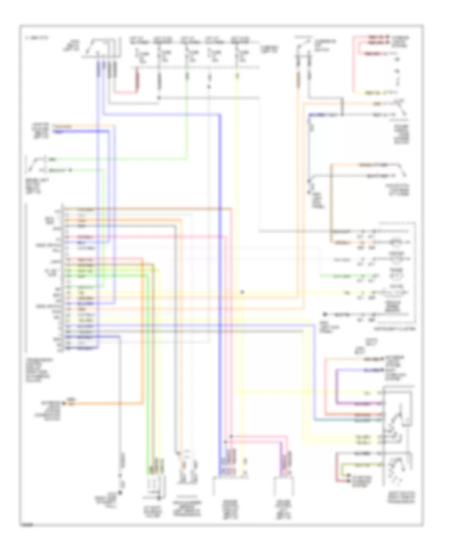
4 Speed A/T Wiring Diagram for Suzuki Sidekick JLX 1995
List of elements for 4 Speed A/T Wiring Diagram for Suzuki Sidekick JLX 1995:
- (left kick panel)
- 1995 vftc c
- 4wd ind
- 4wd switch (top rear of t-case)
- A/t shift solenoid valves
- A10
- A16
- B10
- Brake light switch (below left i/p)
- Cami built
- Cruise control unit (below left i/p)
- Dg(s) (or n/a)
- Engine control module (below left i/p)
- Exterior lights system
- Exterior lights system (combination switch)
- Fuse 15a
- Fuse box (left i/p)
- G09
- G11
- G200
- Gnd
- Hot at all times
- Hot in on or start
- Illum.
- Instrument cluster
- Interior lights system
- Iwata built
- Light
- Main relay (left i/p)
- Monitor coupler (below left i/p)
- Nca
- O/d ind
- Odl
- Overdrive off switch
- P/n ind
- Power/ normal mode change switch
- Pwl
- Pwr
- S1, s2 & s3
- Shg
- Shift interlock system
- Shift switch (right side of transmission)
- Sp & spg
- Spm
- Starting/ charging system
- Transmission control module (right side of steering column)
- Vehicle speed sensor
- Vehicle speed sensor (left rear of transmission)