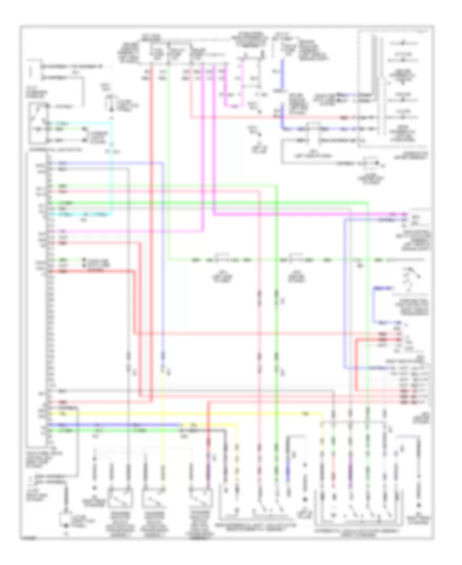
TRANSMISSION
4WD Wiring Diagram for Toyota 4Runner Trail 2011

List of elements for 4WD Wiring Diagram for Toyota 4Runner Trail 2011:
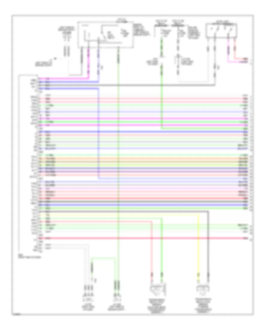
A/T Wiring Diagram (1 of 3) for Toyota 4Runner Trail 2011
List of elements for A/T Wiring Diagram (1 of 3) for Toyota 4Runner Trail 2011:
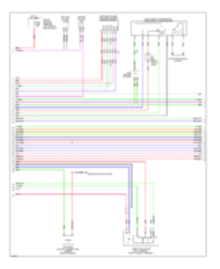
A/T Wiring Diagram (2 of 3) for Toyota 4Runner Trail 2011
List of elements for A/T Wiring Diagram (2 of 3) for Toyota 4Runner Trail 2011:
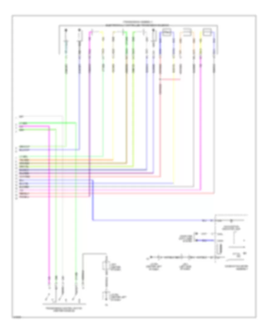
A/T Wiring Diagram (3 of 3) for Toyota 4Runner Trail 2011
List of elements for A/T Wiring Diagram (3 of 3) for Toyota 4Runner Trail 2011:
Rear Differential Lock Wiring Diagram for Toyota 4Runner Trail 2011
List of elements for Rear Differential Lock Wiring Diagram for Toyota 4Runner Trail 2011: