TRANSMISSION
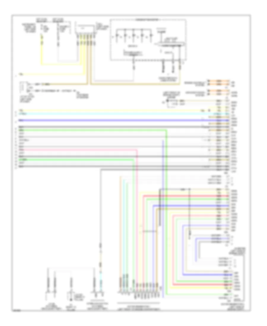
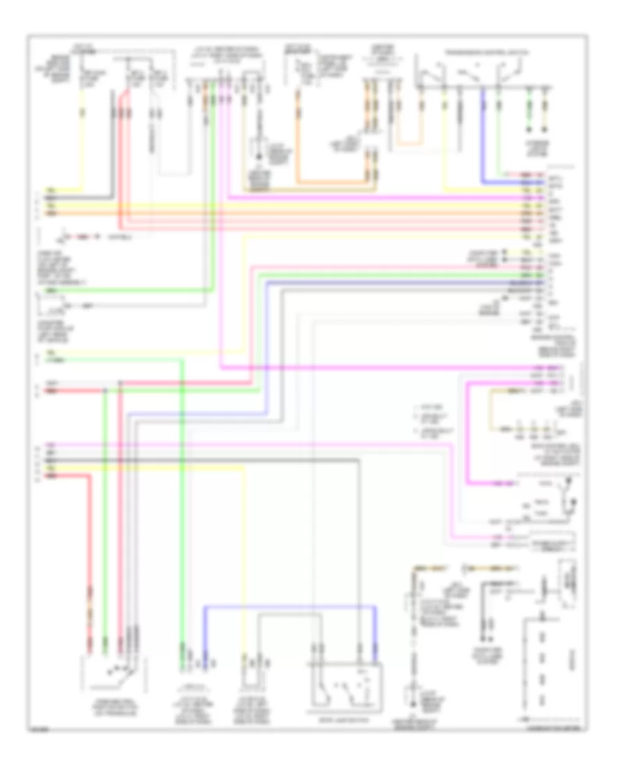
A/T Wiring Diagram, Hybrid (1 of 2) for Toyota Camry CE 2007

List of elements for A/T Wiring Diagram, Hybrid (1 of 2) for Toyota Camry CE 2007:
- (at brake pedal assembly) stop lamp switch
- (in hybrid vehicle battery) battery voltage sensor
- (left front of engine compt) a1
- (left side of dash) j/c a58 & e40
- +b1
- +b2
- +bs
- A58
- A61
- Amd
- Batt
- C4 (top rear of engine)
- C64
- Clk+
- Clk-
- Converter (in hybrid vehicle battery)
- Dc/dc fuse 120a
- E02
- E40
- Efi relay
- Engine controls system
- Engine room j/b (on left side of engine compt)
- Engine room r/b (on left side of engine compt)
- Gmt
- Gmtg
- Gnd
- Hot at all times
- Hsdn
- Htm+
- Htm-
- Hybrid vehicle control ecu (right rear of engine compt)
- Idh
- Igct
- Igct 2 fuse 10a
- Igct fuse 30a
- Igct relay
- Ilk
- In+
- In-
- J/c n6 (in hybrid vehicle battery)
- Me01
- Mmt
- Mmtg
- Mrel
- Mth+
- Mth-
- Nca
- Nodd
- Park/neutral position switch (on transaxle)
- Pnk
- Prec
- Red
- Req+
- Req-
- Smrp
- St1-
- Stop fuse 10a
- Stp
- Vlo
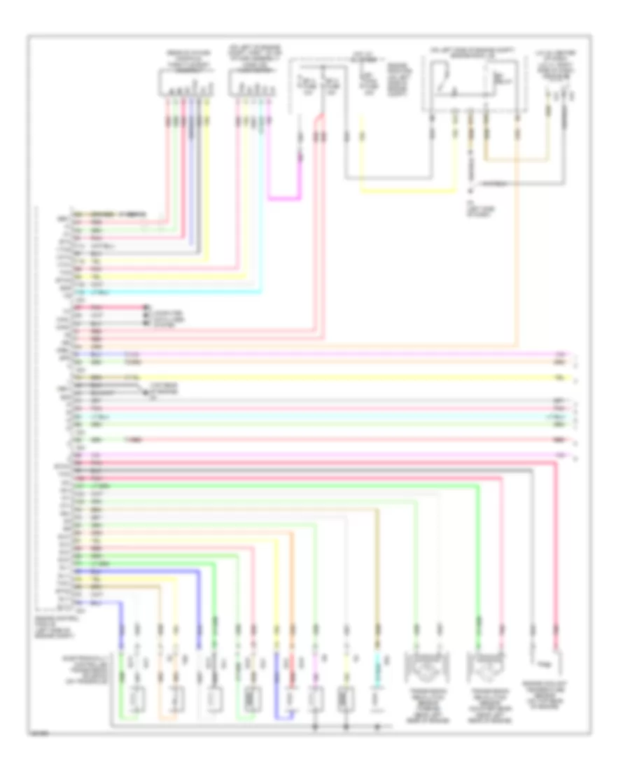
A/T Wiring Diagram, Hybrid (2 of 2) for Toyota Camry CE 2007
List of elements for A/T Wiring Diagram, Hybrid (2 of 2) for Toyota Camry CE 2007:
- (left front of engine compt) j/c a43
- +b2
- A41
- A42
- A62
- Acpb
- Acpe
- Air conditioning system
- Buzzer
- C58
- C59
- C6 (top rear of engine)
- C60
- C61
- Can i/f
- Cbi
- Cei
- Clk+
- Clk-
- Combination meter
- Computer data lines system
- D10
- Drive ic
- Drn1
- Drn2
- Drn3
- Drn4
- Drn5
- Drn6
- Drn8
- Engine controls system
- F12
- G12
- Gauge 2 fuse 7.5a
- Gcs
- Gcsg
- Gmt
- Gmtg
- Gnd
- Gnd1
- Gnd2
- Grf
- Grfg
- Gsn
- Gsng
- Hot in on or start
- Hsdn
- Htm+
- Htm-
- Ign fuse 10a
- Ilk
- Ilki
- Ilko
- Instrument panel j/b (left side of dash)
- Interlock switch (in hybrid vehicle battery)
- Inverter (left side of engine compt)
- J/b 3 (left side of dash)
- J/c a41 & a42 (left side of dash)
- J/c n6 (in hybrid vehicle battery)
- J/c o21 (rear "c" pillar)
- K12
- Mcs
- Mcsg
- Micro computer
- Mmt
- Mmtg
- Motor generator 1 (left front of engine compartment)
- Motor generator 2 (left side of engine compt)
- Mrf
- Mrfg
- Msn
- Msng
- Mth+
- Mth-
- Multi lcd
- Nca
- O1 (right "c" pillar)
- Pnk
- Red
- Req+
- Req-
2.4L
2.4L, A/T Wiring Diagram, Except Hybrid (1 of 2) for Toyota Camry CE 2007
List of elements for 2.4L, A/T Wiring Diagram, Except Hybrid (1 of 2) for Toyota Camry CE 2007:
- (j/c 42: center of dash) (j/c 41: right side of dash) j/c 41 & 42
- (on left of engine compt, part of air intake assembly) mass air flow meter
- (on left side of engine compt) engine room j/b
- (rear of intake manifold) throttle body assembly
- (top rear of engine) c4
- +b2
- A24
- A3 (left side of dash)
- A41
- A42
- C24
- Canh
- Canl
- Computer data lines system
- Dsl
- E02
- E10
- E11
- E12
- E2g
- Efi 2 fuse 15a
- Efi 3 fuse 10a
- Efi main fuse 30a
- Efi relay
- Electronically controlled transmission solenoid (on transaxle)
- Engine control module (left side of engine compt)
- Engine coolant temperature sensor (on top rear of engine)
- Engine room r/b (on left side of engine compt)
- Eta
- Etha
- Etho
- Ethw
- Ge01
- Hot at all times
- Me01
- Mrel
- Nc+
- Nc-
- Nca
- Nt+
- Nt-
- Pnk
- Red
- Sl1+
- Sl1-
- Sl2+
- Sl2-
- Sl3+
- Sl3-
- Slt+
- Slt-
- Spd
- Tha
- Tho
- Tho1
- Thw
- Transmission revolution sensor (counter gear) (near left rear of engine)
- Transmission revolution sensor (turbine) (near left rear of engine)
- Vcta
- Vta
- Vta1
- Vta2
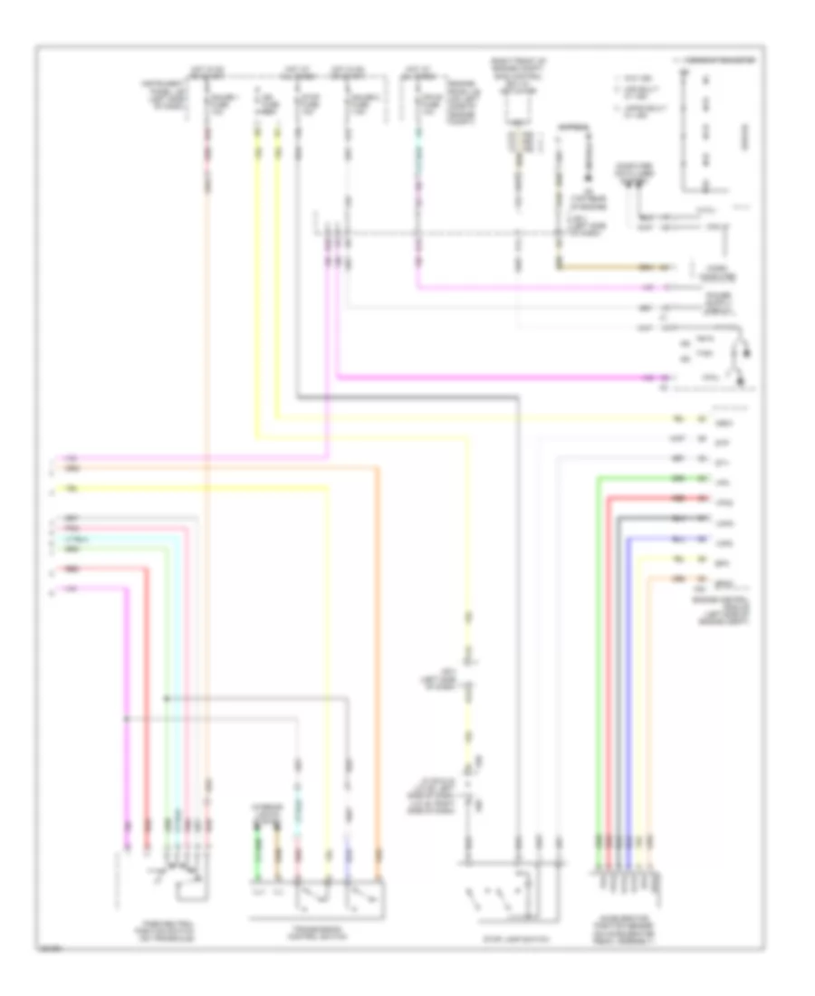
2.4L, A/T Wiring Diagram, Except Hybrid (2 of 2) for Toyota Camry CE 2007
List of elements for 2.4L, A/T Wiring Diagram, Except Hybrid (2 of 2) for Toyota Camry CE 2007:
- (right front of engine compt) skid control ecu w/ actuator
- 4,3,2,l
- A24
- A25 a60 a26
- A58
- Accelerator position sensor (on accelerator pedal assembly)
- B10
- C6 (top rear of engine)
- Can i/f
- Combination meter
- Computer
- Computer data lines system
- D10
- Drive ic
- E40
- Engine control module (left side of engine compt)
- Engine room j/b (on left side of engine compt)
- Epa
- Epa2
- F12
- G12
- Gauge 1 fuse 10a
- Gauge 2 fuse 7.5a
- H16
- Hot at all times
- Hot in on or start
- Ig2
- Ign fuse 10a
- Igsw
- Ill+
- Ill-
- Instrument panel j/b (left side of dash)
- Interior lights system
- J/b 3 (left side of dash)
- J/c 58 & 40 (j/c 58: left side of dash) (j/c 40: right side of dash)
- Japan built
- K12
- Micro
- Mpx-b fuse 10a
- P11
- Park/neutral position switch (on transaxle)
- Pnk
- Q12
- Red
- Sp1
- St1-
- Stop fuse 10a
- Stop lamp switch
- Stp
- Transmission control switch
- Usa built
- Vcp2
- Vcpa
- Vpa
- Vpa2
- W/ vsc
- W/o vsc
3.5L
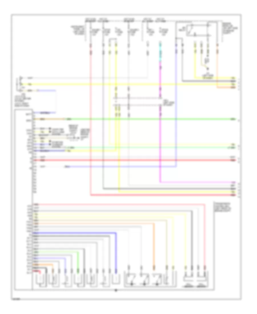
3.5L, A/T Wiring Diagram, Except Hybrid (1 of 2) for Toyota Camry CE 2007
List of elements for 3.5L, A/T Wiring Diagram, Except Hybrid (1 of 2) for Toyota Camry CE 2007:
- (center rear of engine
- (rear of engine compt) j/c 57
- A3 (left side of dash)
- A41
- A42
- Batt
- Can+
- Can-
- Compt)
- Computer data lines system
- E10
- E11
- E12
- Efi 1 fuse 10a
- Efi relay
- Engine room j/b (on left side of engine compt)
- Eo1
- F12
- G12
- Gauge 1 fuse 10a
- Gauge 2 fuse 7.5a
- H16
- Hall sensor
- Hot at all times
- Hot in on or start
- Ig2
- Ign fuse 10a
- Instrument panel j/b (left side of dash)
- J/b 3 (left side of dash)
- J/c 41 & 42 (j/c 42: center of dash) (j/c 41: right side of dash)
- J12
- K12
- Mpx-b fuse 10a
- Ncb
- Nco
- Nsw
- Ntb
- Nto
- Q12
- Red
- Sl1+
- Sl1-
- Sl2+
- Sl2-
- Sl3+
- Sl3-
- Sl4+
- Sl4-
- Slt+
- Slt-
- Slu+
- Slu-
- Spd1
- Sta
- Starting/ charging system
- Stop fuse 10a
- Stp
- Tho1
- Tps1
- Tps2
- Tps3
- Transmission control ecu (left front of engine compt)
3.5L, A/T Wiring Diagram, Except Hybrid (2 of 2) for Toyota Camry CE 2007
List of elements for 3.5L, A/T Wiring Diagram, Except Hybrid (2 of 2) for Toyota Camry CE 2007:
- (center of dash) j/b 4
- (center rear of engine compt)
- (j/c 42: center of dash) (j/c 41: right side of dash) j/c 41 & 42
- +b2
- A11
- A25
- A26
- A41
- A42
- A55
- A58
- A60
- B10
- Batt
- C12
- C4 (top of engine)
- C55
- C7 (center rear of engine compt)
- Can i/f
- Can+
- Can-
- Canister pump module (left rear of vehicle)
- Combination meter
- Computer
- Computer data lines system
- D10
- Drive ic
- E04
- E40
- Ecu ig 2 fuse 7.5a
- Efi 2 fuse 15a
- Efi 3 fuse 10a
- Efi main fuse 30a
- Engine control module (behind right side of dash)
- Engine room r/b (on left side of engine compt)
- F19
- H10
- Hot at all times
- Hot in on or start
- Ig2
- Igsw
- Ill+
- Ill-
- Instrument panel j/b (left side of dash)
- Interior lights system
- J/b 3 (left side of dash)
- J/c 41 & 42 (j/c 42: center of dash) (j/c 41: right side of dash)
- J/c 57 (rear of engine compt)
- J/c 58 & 40 (j/c 58: left side of dash) (j/c 40: right side of dash)
- Japan built
- Mass air flow meter (on left of engine compt, part of air intake assembly)
- Micro
- Mrel
- P11
- Park/neutral position switch (on transaxle)
- Pnk
- Red
- Sftd
- Sftu
- Skid control ecu w/ actuator (at right side of engine compt)
- Sp1
- Spd
- St1-
- Stop lamp switch
- Stp
- Transmission control switch
- Usa built
- Vlvb
- W/ vsc
- W/o vsc