TRANSMISSION
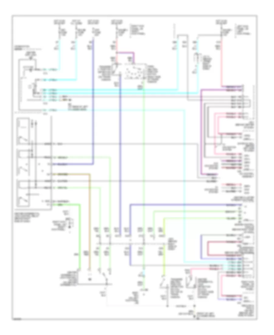
A/T Wiring Diagram (1 of 2) for Toyota Land Cruiser 2007

List of elements for A/T Wiring Diagram (1 of 2) for Toyota Land Cruiser 2007:
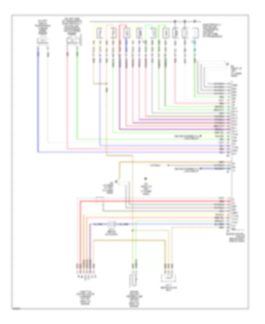
A/T Wiring Diagram (2 of 2) for Toyota Land Cruiser 2007
List of elements for A/T Wiring Diagram (2 of 2) for Toyota Land Cruiser 2007:
Center Differential Lock Wiring Diagram for Toyota Land Cruiser 2007
List of elements for Center Differential Lock Wiring Diagram for Toyota Land Cruiser 2007: