TRANSMISSION
2.4L
2.4L, Overdrive Wiring Diagram, 2WD for Toyota Pickup SR5 1995

List of elements for 2.4L, Overdrive Wiring Diagram, 2WD for Toyota Pickup SR5 1995:
- (i/p harn, top center of dash)
- Cruise control ecu (lower left side of i/p)
- Ect
- Engine control module (right kick panel)
- G200 (left kick panel)
- Gauge fuse 10a
- Hot in on or start
- I4 (i/p harn, top center of dash)
- Instrument cluster
- Integration relay
- J/b 1 (left kick panel)
- O/d
- O/d main switch (column shft- center of dash) (floor shft- below center console)
- O/d off indic.
- O/d relay (behind left side of dash)
- O/d solenoid (on transmission)
- Turn fuse 10a
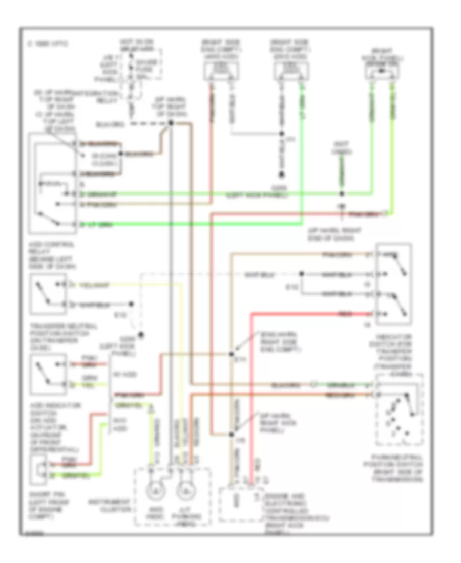
2.4L, Transfer Case Wiring Diagram, A/T for Toyota Pickup SR5 1995
List of elements for 2.4L, Transfer Case Wiring Diagram, A/T for Toyota Pickup SR5 1995:
- (eng harn, right side eng compt)
- (i/p harn, right end of dash)
- (i/p harn, right kick panel)
- (i/p harn, top right of dash)
- (i9: i/p harn, top right of dash i3: i/p harn, top left of dash)
- (not used)
- (right kick panel) diode d6
- (right side eng compt) (2wd add) vsv
- (right side eng compt) (4wd add) vsv
- (transfer case)
- 1995 vftc c
- 4wd
- 4wd indic.
- A/t parking indic.
- A10
- A12
- Add
- Add control relay (behind left side of dash)
- Add indicator switch (on add actuator, on front of front differential)
- E11
- E12
- Engine and electronic controlled transmission ecu (right kick panel)
- G200 (left kick panel)
- Gauge fuse 10a
- Hot in on or start
- I11
- I13
- I15
- I9 (can) i3 (usa)
- Indicator switch (for transfer position)
- Instrument cluster
- Integration relay
- J/b 1 (left kick panel)
- Park/neutral position switch (right side of transmission)
- Red
- Short pin (left front of engine compt)
- Transfer neutral position switch (on transfer case)
- W/ add
- W/o
Transfer Case Wiring Diagram, M/T for Toyota Pickup SR5 1995
List of elements for Transfer Case Wiring Diagram, M/T for Toyota Pickup SR5 1995:
- (eng harn, right side of eng)
- (i/p harn, right kick panel)
- (i/p harn, right kick panel) i15
- (i9: i/p harn, top right side of dash i13: i/p harn, right end of dash)
- 2.4l
- 3.0l
- 4wd
- 4wd indic.
- A12
- Add control relay (left side of dash)
- Add indicator switch (front differential)
- C 1995 vftc
- E20
- Engine control module (right kick panel)
- G200 (left kick panel)
- Gauge fuse 10a
- Hot in on or start
- I11
- I13 (canada) i9 (usa)
- I15
- I9 (i/p harn, top right side of dash)
- Indicator switch (transfer position) (on transfer case)
- Instrument cluster
- Integration relay
- J/b 1 (left kick panel)
- Red
- Vsv v1 (2wd add) (right side eng compt)
- Vsv v2 (4wd add) (right side eng compt)
- W/ add
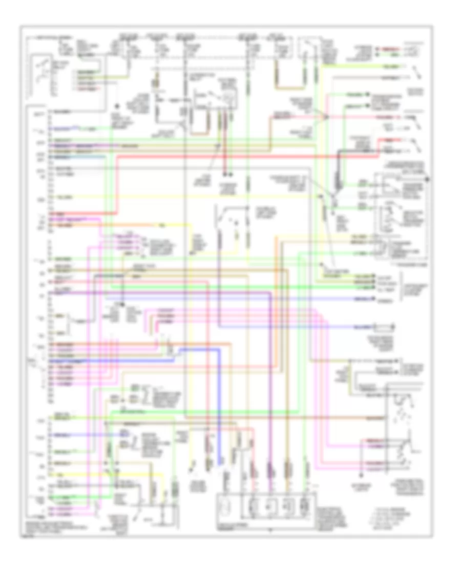
Transmission Wiring Diagram for Toyota Pickup SR5 1995
List of elements for Transmission Wiring Diagram for Toyota Pickup SR5 1995:
- (4wd)
- (column shift only)
- (console shft) (floor shft)
- (right kick panel)
- (right side of engine compt) e11
- (top center of dash)
- (top right side of dash) i9
- (top right side of engine) e12
- * w/ 2.4l engine
- ** *
- ** nca
- ** w/ 3.0l v6 engine
- ***
- *** 3.0l v6 w/ 4wd
- ****
- **** all 2.4l, 3.0l v6 w/ 2wd
- 4wd
- Batt
- C17
- Cig fuse 15a
- Cruise control system
- Data link connector 1 (right side eng compt)
- Dg te2 t e1
- Efi fuse 15a
- Efi main
- Electronic controlled transmission solenoid and vehicle speed sensor
- Engine and electronic controlled transmission ecu (right kick panel)
- Engine coolant temperature sensor (on intake manifold)
- Exterior lights
- G100 (front of left front fender)
- G117 (cam bearing cap)
- G120 (intake mani- fold)
- G201 (right side of i/p)
- Gauge fuse 10a
- Hot at all times
- Hot in acc or on
- Hot in on or start
- I15
- I15 (right kick panel)
- I15 (rt kick pnl)
- I4 (top center of dash)
- I6 i8 (center of dash)
- Idl
- Ign fuse 7.5a
- Indicator switch (transfer position)
- Indicator switch (transfer position) (on t-case)
- Instrument cluster system
- Integration relay
- Interior lights system
- Interior lights system (floor shift)
- J/b 1 (left kick panel)
- N **
- Nca
- Nca **
- No. 1
- No. 2
- No. 3
- No. 4
- Norm
- O/d main switch
- O/d off
- O/d relay (left side of dash)
- O/d solenoid (right rear of engine compt)
- Od1
- Od2
- Oil
- Oil temp
- Oil temperature sensor (right front trans pan)
- Park/neutral position switch (right side of transmission)
- Pattern select switch
- Pwr
- Pwr indic
- R/b 2 (right eng compt)
- Red
- Relay
- Sp1
- Sp2
- Speedo
- Sta
- Starting/ charging system
- Stop fuse 15a
- Stop light switch (above brake pedal)
- Stp
- Te2
- Th01
- Th02 te2
- Throttle position sensor (on throttle body)
- Thw
- Transfer case
- Transfer fluid temperature sensor
- Transfer pressure switch (for add)
- Transmissions systems (a/t transfer case circuit)
- Turn fuse 10a
- Vcc
- Vehicle speed sensor
- Vta
3.0L
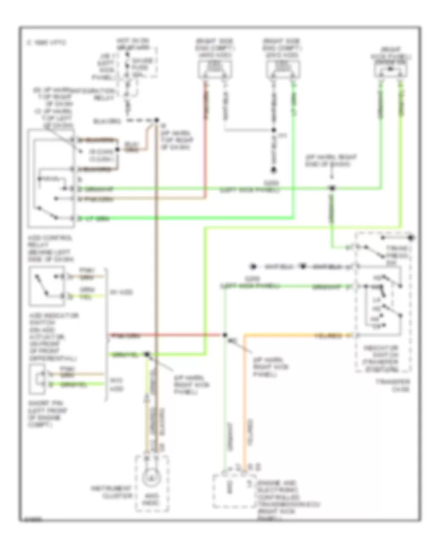
3.0L, Transfer Case Wiring Diagram, A/T for Toyota Pickup SR5 1995
List of elements for 3.0L, Transfer Case Wiring Diagram, A/T for Toyota Pickup SR5 1995:
- (i/p harn, right end of dash)
- (i/p harn, right kick panel)
- (i9: i/p harn, top right of dash i3: i/p harn, top left of dash)
- (left kick panel)
- (right kick panel) diode d6
- (right side eng compt) (2wd add) vsv
- (right side eng compt) (4wd add) vsv
- 1995 vftc c
- 4wd
- 4wd indic.
- A12
- Add
- Add control relay (behind left side of dash)
- Add indicator switch (on add actuator, on front of front differential)
- Engine and electronic controlled transmission ecu (right kick panel)
- G200
- G200 (left kick panel)
- Gauge fuse 10a
- Hot in on or start
- I11
- I13
- I15
- I9 (can) i3 (usa)
- I9 (i/p harn, top right of dash)
- Indicator switch (transfer position)
- Instrument cluster
- Integration relay
- J/b 1 (left kick panel)
- Short pin (left front of engine compt)
- Trans press sw
- Transfer case
- W/ add
- W/o
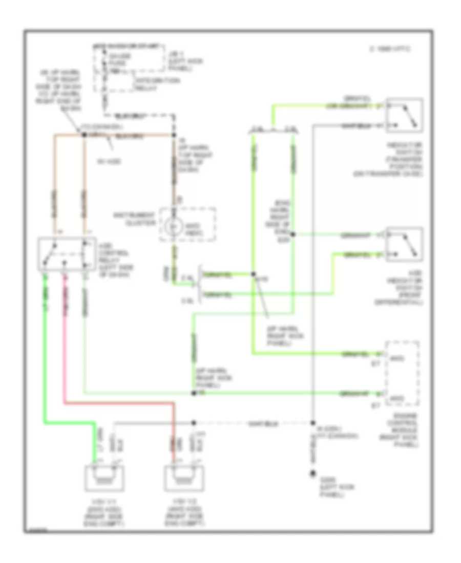
Transfer Case Wiring Diagram, M/T for Toyota Pickup SR5 1995
List of elements for Transfer Case Wiring Diagram, M/T for Toyota Pickup SR5 1995:
- (eng harn, right side of eng)
- (i/p harn, right kick panel)
- (i/p harn, right kick panel) i15
- (i9: i/p harn, top right side of dash i13: i/p harn, right end of dash)
- 2.4l
- 3.0l
- 4wd
- 4wd indic.
- A12
- Add control relay (left side of dash)
- Add indicator switch (front differential)
- C 1995 vftc
- E20
- Engine control module (right kick panel)
- G200 (left kick panel)
- Gauge fuse 10a
- Hot in on or start
- I11
- I13 (canada) i9 (usa)
- I15
- I9 (i/p harn, top right side of dash)
- Indicator switch (transfer position) (on transfer case)
- Instrument cluster
- Integration relay
- J/b 1 (left kick panel)
- Red
- Vsv v1 (2wd add) (right side eng compt)
- Vsv v2 (4wd add) (right side eng compt)
- W/ add
Transmission Wiring Diagram for Toyota Pickup SR5 1995
List of elements for Transmission Wiring Diagram for Toyota Pickup SR5 1995:
- (4wd)
- (column shift only)
- (console shft) (floor shft)
- (right kick panel)
- (right side of engine compt) e11
- (top center of dash)
- (top right side of dash) i9
- (top right side of engine) e12
- * w/ 2.4l engine
- ** *
- ** nca
- ** w/ 3.0l v6 engine
- ***
- *** 3.0l v6 w/ 4wd
- ****
- **** all 2.4l, 3.0l v6 w/ 2wd
- 4wd
- Batt
- C17
- Cig fuse 15a
- Cruise control system
- Data link connector 1 (right side eng compt)
- Dg te2 t e1
- Efi fuse 15a
- Efi main
- Electronic controlled transmission solenoid and vehicle speed sensor
- Engine and electronic controlled transmission ecu (right kick panel)
- Engine coolant temperature sensor (on intake manifold)
- Exterior lights
- G100 (front of left front fender)
- G117 (cam bearing cap)
- G120 (intake mani- fold)
- G201 (right side of i/p)
- Gauge fuse 10a
- Hot at all times
- Hot in acc or on
- Hot in on or start
- I15
- I15 (right kick panel)
- I15 (rt kick pnl)
- I4 (top center of dash)
- I6 i8 (center of dash)
- Idl
- Ign fuse 7.5a
- Indicator switch (transfer position)
- Indicator switch (transfer position) (on t-case)
- Instrument cluster system
- Integration relay
- Interior lights system
- Interior lights system (floor shift)
- J/b 1 (left kick panel)
- N **
- Nca
- Nca **
- No. 1
- No. 2
- No. 3
- No. 4
- Norm
- O/d main switch
- O/d off
- O/d relay (left side of dash)
- O/d solenoid (right rear of engine compt)
- Od1
- Od2
- Oil
- Oil temp
- Oil temperature sensor (right front trans pan)
- Park/neutral position switch (right side of transmission)
- Pattern select switch
- Pwr
- Pwr indic
- R/b 2 (right eng compt)
- Red
- Relay
- Sp1
- Sp2
- Speedo
- Sta
- Starting/ charging system
- Stop fuse 15a
- Stop light switch (above brake pedal)
- Stp
- Te2
- Th01
- Th02 te2
- Throttle position sensor (on throttle body)
- Thw
- Transfer case
- Transfer fluid temperature sensor
- Transfer pressure switch (for add)
- Transmissions systems (a/t transfer case circuit)
- Turn fuse 10a
- Vcc
- Vehicle speed sensor
- Vta