TRANSMISSION
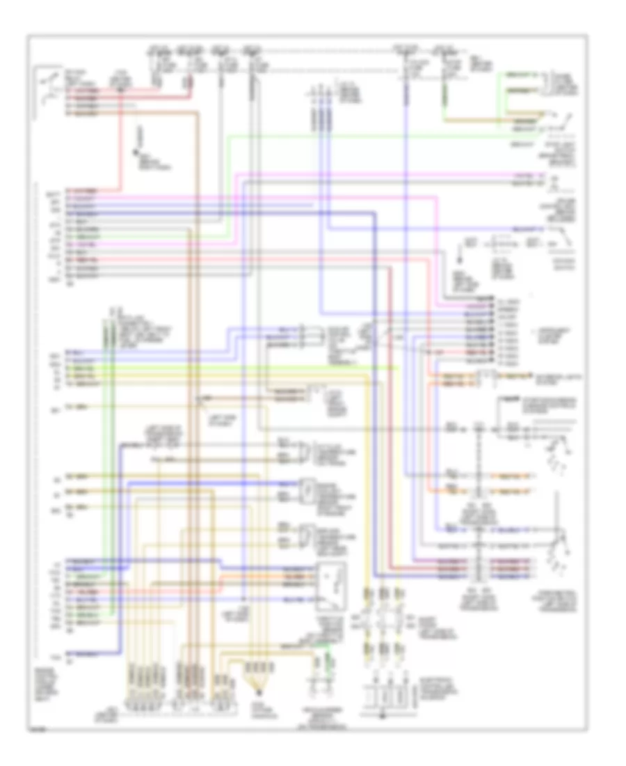
Transmission Wiring Diagram for Toyota Previa DX 1996
List of elements for Transmission Wiring Diagram for Toyota Previa DX 1996:
- "2" indic
- "d" indic
- "l" indic
- "n" indic
- "p" indic
- "r" indic
- (left side of dash)
- (left side of transmission)
- (left side of transmission) short conn
- (lockup)
- (top center of dash) i134
- A/t fluid temperature sensor (on trans)
- A18
- A19
- B19
- Batt
- C13
- Cruise control ecu (behind left dash)
- D19
- Data link connector 1 ( below left front seat leg, next to fuel lid opener lever)
- E01
- E02
- Efi fuse 15a
- Egr gas temperature sensor (left rear eng compt)
- Electronic controlled transmission solenoid
- Engine control module (under driver's seat)
- Engine coolant temperature sensor (right front of engine)
- Exterior lights system
- G125 (intake manifold)
- G202 (behind left side of dash)
- Hot at all times
- Hot in on or acc
- Hot in on or start
- Hot in start
- I127
- I129
- I129 (left side of dash)
- Idl
- Idle air control valve (on throttle body assembly)
- Ign fuse 7.5a
- Instrument cluster system
- Isc1
- Isc2
- J/b 3 (center of dash)
- J/c 13 (behind center of dash)
- J/c 16 (behind center of dash)
- J/c 21 (left front engine compt)
- Mfi main relay (left dash)
- No. 1
- No. 2
- No. 3
- Noise filter (center of dash)
- Nsw
- O/d main
- O/d off
- Od1
- Od2
- Oil indic
- Oilw
- Park/neutral position switch (left side of transmission)
- R/b 1 (center of dash)
- Red
- S21
- S22
- S22 s21
- S23
- S23 s24
- S24
- Short conn (left side of transmission)
- Short conns
- Sp1
- Sp2
- Speedo
- St fuse 7.5a
- St-a fuse 7.5a
- Sta
- Starting/charging & engine controls systems
- Stop fuse 20a
- Stop light switch (brake pedal bracket)
- Stp
- Switch
- T/m acc fuse 7.5a
- Te1
- Te2
- Thg
- Tho
- Throttle position sensor (on throttle body assembly)
- Thw
- Vehicle speed sensor (for e.c.t.) (on transmission)
- Vta
 Русский