TRANSMISSION
A/T Wiring Diagram for Toyota RAV4 1998

List of elements for A/T Wiring Diagram for Toyota RAV4 1998:
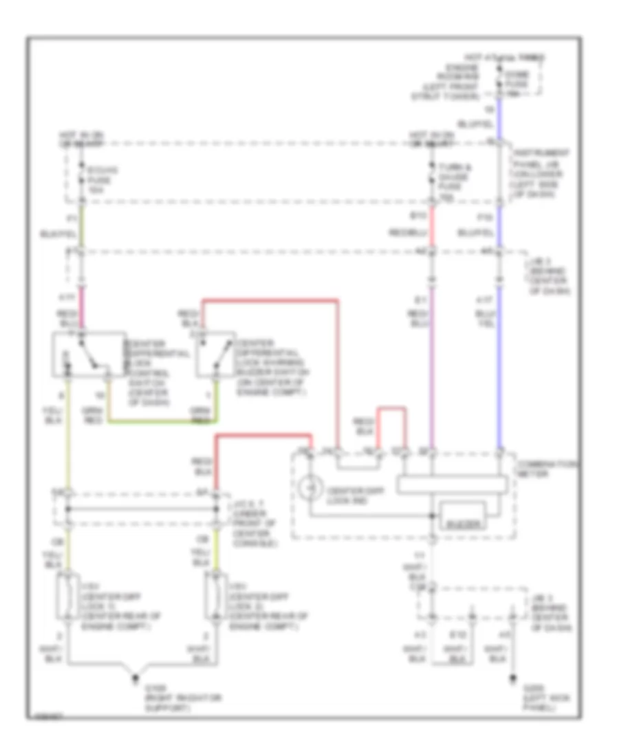
Center Differential Lock Wiring Diagram, M/T for Toyota RAV4 1998
List of elements for Center Differential Lock Wiring Diagram, M/T for Toyota RAV4 1998: