TRANSMISSION
3.0L
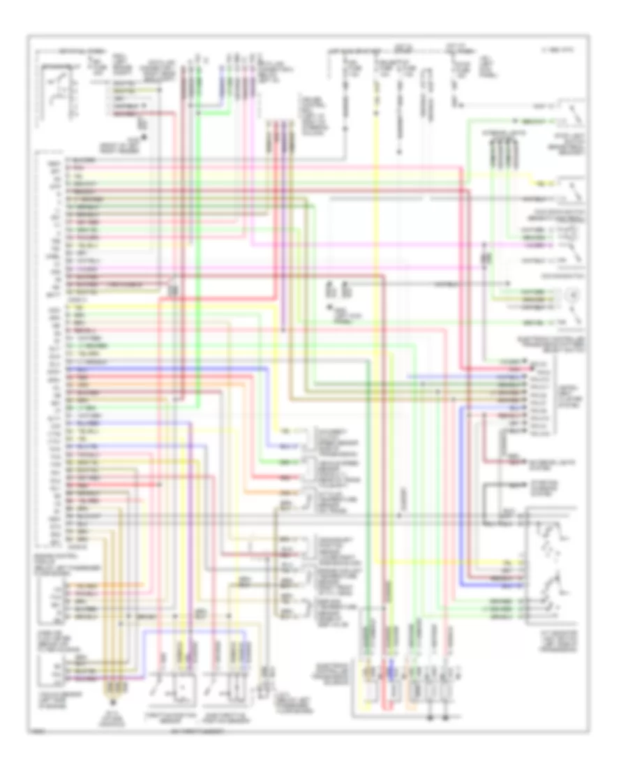
3.0L Non-Turbo, Transmission Wiring Diagram for Toyota Supra 1993

List of elements for 3.0L Non-Turbo, Transmission Wiring Diagram for Toyota Supra 1993:
3.0L Turbo, Transmission Wiring Diagram for Toyota Supra 1993
List of elements for 3.0L Turbo, Transmission Wiring Diagram for Toyota Supra 1993: