TRANSMISSION
2.4L
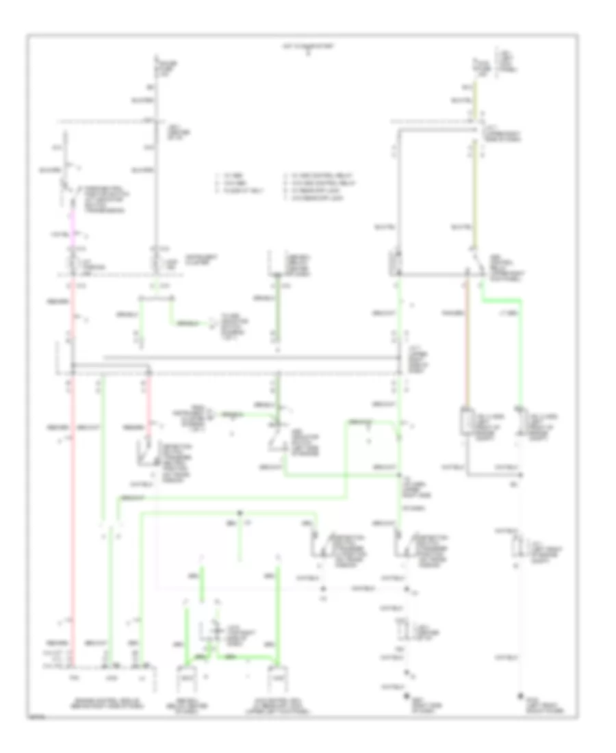
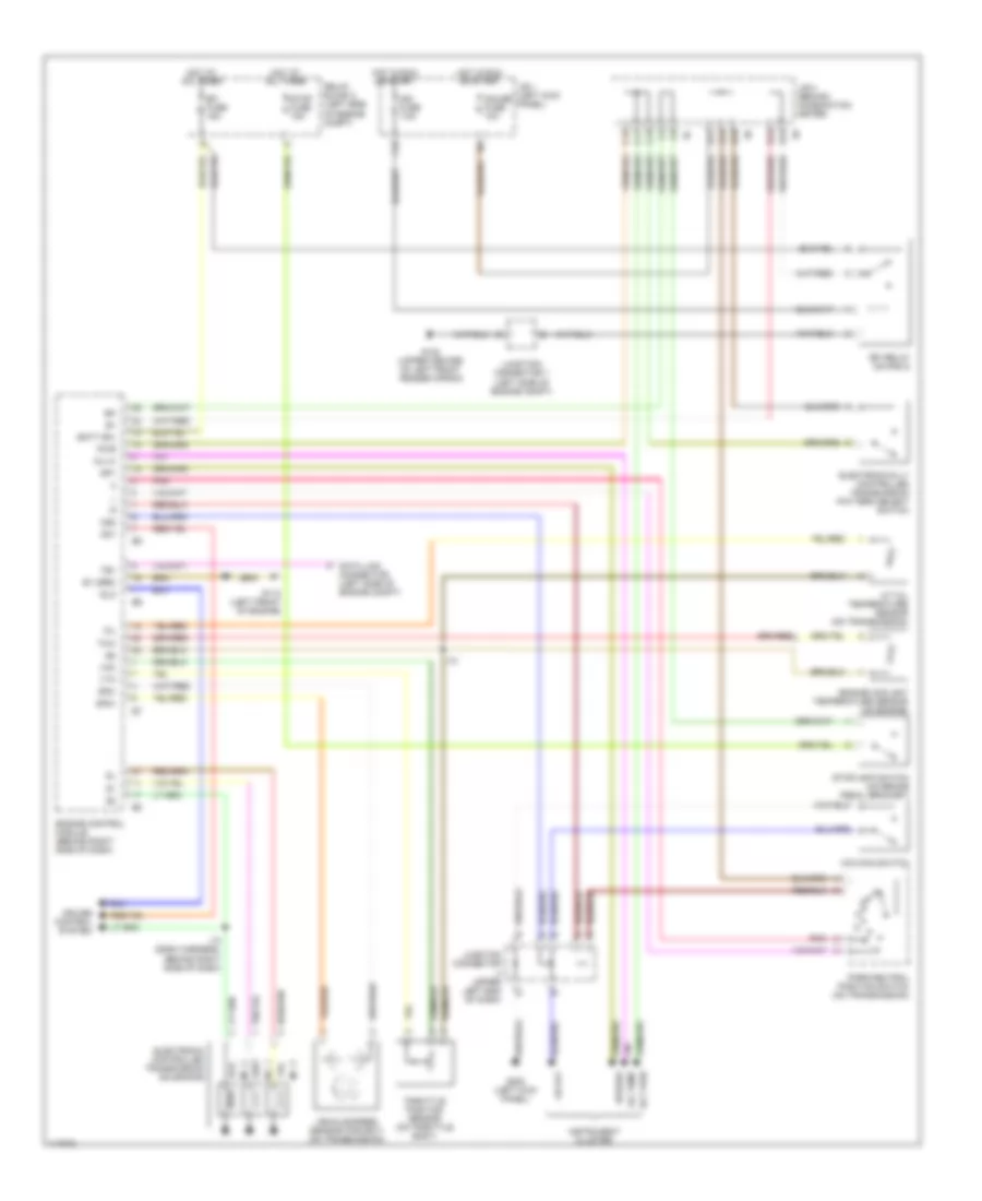
2.4L, Overdrive Wiring Diagram for Toyota Tacoma 1997

List of elements for 2.4L, Overdrive Wiring Diagram for Toyota Tacoma 1997:
- (w/ tach)
- (w/o tach)
- A5 d1
- C12
- C13
- Canada
- Cig fuse 15a
- Combination meter
- Cruise control ecu (on right kick panel)
- D13
- D15
- D16
- D17
- D18
- D19
- Diode (behind top center of dash)
- Diode (behind top right side of dash)
- F19
- F20
- G201 (right side of dash)
- Guage fuse 10a
- Hot in accy or on
- Hot in on or start
- J/b 1 (behind dash, left side of steering column)
- J/b 3 (behind dash, above steering column)
- Junction connector 2 (behind left side of dash)
- Junction connector 4 (behind left side of dash)
- Junction connector 6 (above glove box) (w/ cruise control only)
- O/d cut relay (on right side of engine compt) (w/ cruise control)
- O/d main switch
- O/d off
- O/d solenoid (on transmission)
- Park/ neutral position switch (on transmission)
- Pnk
- Usa
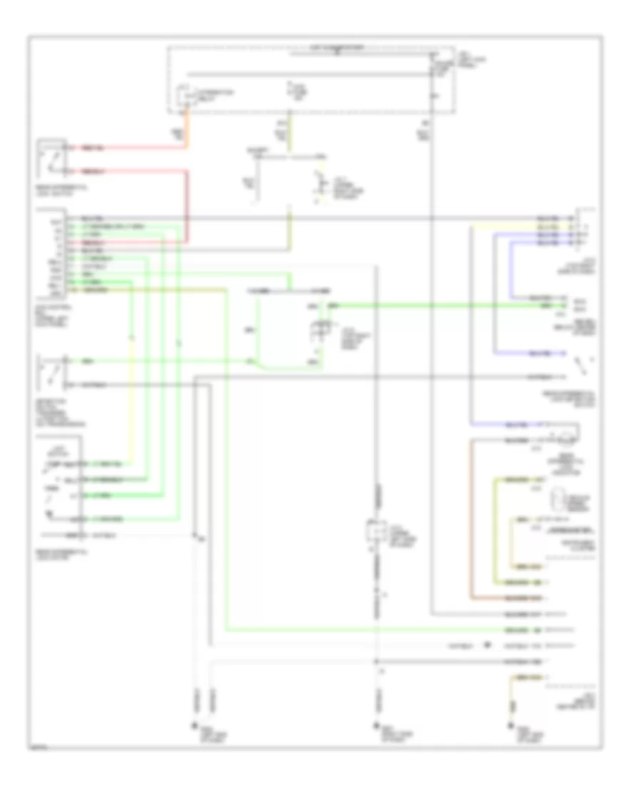
4WD Wiring Diagram, with 2-4 Select Switch for Toyota Tacoma 1997
List of elements for 4WD Wiring Diagram, with 2-4 Select Switch for Toyota Tacoma 1997:
- (i/p harness, upper right side of dash) i10
- 2-4
- 2-4 select motor (on transmission)
- 2-4 select switch
- 4wd
- 4wd ecu (upper left kick panel)
- 4wd fuse 15a
- 4wd ind
- A/t ind switch
- A/t parking ind
- A10
- Abs ecu (below center of dash)
- Add indicator switch (left side of engine)
- B12
- C10
- C12
- C13
- D10
- D12
- D14
- D17
- D19
- Detection switch (transfer l4 position) (on trans- mission)
- Detection switch (transfer neutral position) (on trans- mission)
- Detection switch (transfer position) (on trans- mission)
- Engine control module (behind right side of dash)
- Exi
- Exi3
- F18
- F20
- Floor a/t
- Floor a/t only
- G102 (left front shock tower)
- G201 (right side of dash)
- G202 (left end of dash)
- Gauge fuse 10a
- Gnd
- Hot in run or start
- I10
- Ind
- Instrument cluster
- J/b 1 (left kick panel)
- J/b 3 (center of i/p)
- J/c 1 (left front of engine compt)
- J/c 4 (top left side of dash)
- J/c 6 (top right side of dash)
- J/c 7 (upper right side of dash)
- M/t
- Park/ neutral position switch
- Red
- Rl1
- Rl2
- Spd
- Tfn
- Th+
- Th-
- Vehicle speed sensor
- Vsv 2 (add) (left front of engine compt)
- Vsv 4 (add) (left front of engine compt)
- W/ abs
- W/o abs
4WD Wiring Diagram, without 2-4 Select Switch for Toyota Tacoma 1997
List of elements for 4WD Wiring Diagram, without 2-4 Select Switch for Toyota Tacoma 1997:
- (on trans- mission)
- 2.7l
- 3.4l a/t
- 3.4l m/t
- 4wd
- 4wd control ecu (w/ rear diff lock) (upper left kick panel)
- 4wd fuse 15a
- 4wd ind
- :floor a/t only
- :w/ abs
- :w/ add control relay
- :w/ rear diff lock
- :w/o abs
- :w/o add control relay
- :w/o rear diff lock
- A/t parking ind
- A10
- Abs ecu (below
- Abs ecu (below center of dash)
- Add control relay (upper right kick panel)
- Add indicator switch (left side of engine)
- B12
- C10
- C13
- Center of dash)
- D14
- D17
- D19
- Detection switch (transfer l4 position) (on trans- mission)
- Detection switch (transfer neutral position)
- Detection switch (transfer position) (on trans- mission)
- Engine control module (behind right side of dash)
- Exi
- Exi3
- F18
- F20
- From instrument cluster (diagram 1 of 1)
- G102 (left front shock tower)
- G201 (right side of dash)
- Gauge fuse 10a
- Hot in on or start
- I10
- I10 (i/p harn, upper right side
- Instrument cluster
- J/b 1 (left kick panel)
- J/b 3 (center of i/p)
- J/c 1 (left front of engine compt)
- J/c 6 (top right side of dash)
- J/c 7 (upper right side of dash)
- Of dash)
- Park/neutral position switch (a/t indicator switch) (transmission)
- Tfn
- To add indicator switch (diagram 1 of 1)
- Vsv 2 (add) (left front of engine compt)
- Vsv 4 (add) (left front of engine compt)
Rear Differential Lock Wiring Diagram for Toyota Tacoma 1997
List of elements for Rear Differential Lock Wiring Diagram for Toyota Tacoma 1997:
- (speedometer)
- 3.4l
- 4wd
- 4wd control ecu (upper left kick panel)
- 4wd fuse 15a
- A10
- Abs ecu (below center of dash)
- B12
- C10
- C12
- C13
- D10
- D12
- D15
- D17
- Detection switch (transfer l4 position) (on transmission)
- Except 3.4l
- Exi2
- Exi3
- F18
- F20
- Free
- G201 (right side of dash)
- G202 (left end of dash)
- Gauge fuse 10a
- Gnd
- Hot in on or start
- I10
- Instrument cluster
- Integration relay
- J/b 1 (left kick panel)
- J/b 3 (behind center of i/p)
- J/c 2 (upper left side of dash)
- J/c 5 (top right side of dash)
- J/c 6 (top right side of dash)
- J/c 7 (upper right side of dash)
- Limit switch
- Lock
- Rear differential lock switch
- Rear differential lock detection switch
- Rear differential lock indicator
- Rear differential lock motor
- Rel1
- Rel2
- Rlp
- Spd
- Vehicle speed sensor
- W/ abs
- W/o abs
Transfer Case Wiring Diagram, with 2-4 Select Switch for Toyota Tacoma 1997
List of elements for Transfer Case Wiring Diagram, with 2-4 Select Switch for Toyota Tacoma 1997:
- (i/p harness, upper right side of dash) i10
- 2-4
- 2-4 select motor (on transmission)
- 2-4 select switch
- 4wd
- 4wd ecu (upper left kick panel)
- 4wd fuse 15a
- 4wd ind
- A/t ind switch
- A/t parking ind
- A10
- Abs ecu (below center of dash)
- Add indicator switch (left side of engine)
- B12
- C10
- C12
- C13
- D10
- D12
- D14
- D17
- D19
- Detection switch (transfer l4 position) (on trans- mission)
- Detection switch (transfer neutral position) (on trans- mission)
- Detection switch (transfer position) (on trans- mission)
- Engine control module (behind right side of dash)
- Exi
- Exi3
- F18
- F20
- Floor a/t
- Floor a/t only
- G102 (left front shock tower)
- G201 (right side of dash)
- G202 (left end of dash)
- Gauge fuse 10a
- Gnd
- Hot in run or start
- I10
- Ind
- Instrument cluster
- J/b 1 (left kick panel)
- J/b 3 (center of i/p)
- J/c 1 (left front of engine compt)
- J/c 4 (top left side of dash)
- J/c 6 (top right side of dash)
- J/c 7 (upper right side of dash)
- M/t
- Park/ neutral position switch
- Red
- Rl1
- Rl2
- Spd
- Tfn
- Th+
- Th-
- Vehicle speed sensor
- Vsv 2 (add) (left front of engine compt)
- Vsv 4 (add) (left front of engine compt)
- W/ abs
- W/o abs
Transfer Case Wiring Diagram, without 2-4 Select Switch for Toyota Tacoma 1997
List of elements for Transfer Case Wiring Diagram, without 2-4 Select Switch for Toyota Tacoma 1997:
- (on trans- mission)
- 2.7l
- 3.4l a/t
- 3.4l m/t
- 4wd
- 4wd control ecu (w/ rear diff lock) (upper left kick panel)
- 4wd fuse 15a
- 4wd ind
- :floor a/t only
- :w/ abs
- :w/ add control relay
- :w/ rear diff lock
- :w/o abs
- :w/o add control relay
- :w/o rear diff lock
- A/t parking ind
- A10
- Abs ecu (below
- Abs ecu (below center of dash)
- Add control relay (upper right kick panel)
- Add indicator switch (left side of engine)
- B12
- C10
- C13
- Center of dash)
- D14
- D17
- D19
- Detection switch (transfer l4 position) (on trans- mission)
- Detection switch (transfer neutral position)
- Detection switch (transfer position) (on trans- mission)
- Engine control module (behind right side of dash)
- Exi
- Exi3
- F18
- F20
- From instrument cluster (diagram 1 of 1)
- G102 (left front shock tower)
- G201 (right side of dash)
- Gauge fuse 10a
- Hot in on or start
- I10
- I10 (i/p harn, upper right side
- Instrument cluster
- J/b 1 (left kick panel)
- J/b 3 (center of i/p)
- J/c 1 (left front of engine compt)
- J/c 6 (top right side of dash)
- J/c 7 (upper right side of dash)
- Of dash)
- Park/neutral position switch (a/t indicator switch) (transmission)
- Tfn
- To add indicator switch (diagram 1 of 1)
- Vsv 2 (add) (left front of engine compt)
- Vsv 4 (add) (left front of engine compt)
2.7L
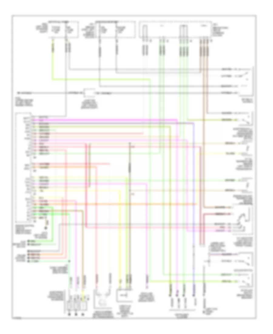
2.7L, A/T Wiring Diagram for Toyota Tacoma 1997
List of elements for 2.7L, A/T Wiring Diagram for Toyota Tacoma 1997:
- (behind dash, above steering column)
- (behind dash, left
- (left kick panel) g200
- (upper left end of dash) junction connector 4
- 4wd
- 4wd detection switch
- A/t indicator light switch (under central trans tunnel)
- A/t oil temperature sensor (left side of transmission)
- Batt
- C11
- C12
- C13
- Cruise control system
- D14
- D16
- D17
- Data link connector 1 (left side of engine compt)
- Ect pwr
- Efi fuse 15a
- Efi relay (on r/b 2)
- Electronic controlled transmission solenoids
- Electronically controlled transmission pattern select switch
- Engine control module (behind right side of dash)
- Engine coolant temperature sensor (on engine)
- F15
- G102 (upper center of left front fender apron)
- G110 (left front of engine)
- Gauge fuse 10a
- Hot at all times r/b 2 (left side of engine compt)
- Hot in on or start j/b 1
- I10
- I10 (dash harness, behind right side of dash)
- Idl0
- Ign fuse 7.5a
- Instrument cluster
- J/b 3
- Junction connector 1 (left side of engine compt)
- No. 1
- No. 2
- No. 3
- O/d main switch
- Od off
- Od1
- Od2
- Oil
- Oil temp
- Oil-w
- Pnk
- Pwr
- Side of steering column)
- Sp1
- Sp2+
- Sp2-
- Speedo
- Stop fuse 15a
- Stoplamp switch (brake pedal bracket)
- Te1
- Throttle position sensor (on throttle body)
- Thw
- Vcc
- Vehicle speed sensor (for ect) (on transmission)
- Vta
4WD Wiring Diagram, with 2-4 Select Switch for Toyota Tacoma 1997
List of elements for 4WD Wiring Diagram, with 2-4 Select Switch for Toyota Tacoma 1997:
- (i/p harness, upper right side of dash) i10
- 2-4
- 2-4 select motor (on transmission)
- 2-4 select switch
- 4wd
- 4wd ecu (upper left kick panel)
- 4wd fuse 15a
- 4wd ind
- A/t ind switch
- A/t parking ind
- A10
- Abs ecu (below center of dash)
- Add indicator switch (left side of engine)
- B12
- C10
- C12
- C13
- D10
- D12
- D14
- D17
- D19
- Detection switch (transfer l4 position) (on trans- mission)
- Detection switch (transfer neutral position) (on trans- mission)
- Detection switch (transfer position) (on trans- mission)
- Engine control module (behind right side of dash)
- Exi
- Exi3
- F18
- F20
- Floor a/t
- Floor a/t only
- G102 (left front shock tower)
- G201 (right side of dash)
- G202 (left end of dash)
- Gauge fuse 10a
- Gnd
- Hot in run or start
- I10
- Ind
- Instrument cluster
- J/b 1 (left kick panel)
- J/b 3 (center of i/p)
- J/c 1 (left front of engine compt)
- J/c 4 (top left side of dash)
- J/c 6 (top right side of dash)
- J/c 7 (upper right side of dash)
- M/t
- Park/ neutral position switch
- Red
- Rl1
- Rl2
- Spd
- Tfn
- Th+
- Th-
- Vehicle speed sensor
- Vsv 2 (add) (left front of engine compt)
- Vsv 4 (add) (left front of engine compt)
- W/ abs
- W/o abs
4WD Wiring Diagram, without 2-4 Select Switch for Toyota Tacoma 1997
List of elements for 4WD Wiring Diagram, without 2-4 Select Switch for Toyota Tacoma 1997:
- (on trans- mission)
- 2.7l
- 3.4l a/t
- 3.4l m/t
- 4wd
- 4wd control ecu (w/ rear diff lock) (upper left kick panel)
- 4wd fuse 15a
- 4wd ind
- :floor a/t only
- :w/ abs
- :w/ add control relay
- :w/ rear diff lock
- :w/o abs
- :w/o add control relay
- :w/o rear diff lock
- A/t parking ind
- A10
- Abs ecu (below
- Abs ecu (below center of dash)
- Add control relay (upper right kick panel)
- Add indicator switch (left side of engine)
- B12
- C10
- C13
- Center of dash)
- D14
- D17
- D19
- Detection switch (transfer l4 position) (on trans- mission)
- Detection switch (transfer neutral position)
- Detection switch (transfer position) (on trans- mission)
- Engine control module (behind right side of dash)
- Exi
- Exi3
- F18
- F20
- From instrument cluster (diagram 1 of 1)
- G102 (left front shock tower)
- G201 (right side of dash)
- Gauge fuse 10a
- Hot in on or start
- I10
- I10 (i/p harn, upper right side
- Instrument cluster
- J/b 1 (left kick panel)
- J/b 3 (center of i/p)
- J/c 1 (left front of engine compt)
- J/c 6 (top right side of dash)
- J/c 7 (upper right side of dash)
- Of dash)
- Park/neutral position switch (a/t indicator switch) (transmission)
- Tfn
- To add indicator switch (diagram 1 of 1)
- Vsv 2 (add) (left front of engine compt)
- Vsv 4 (add) (left front of engine compt)
Rear Differential Lock Wiring Diagram for Toyota Tacoma 1997
List of elements for Rear Differential Lock Wiring Diagram for Toyota Tacoma 1997:
- (speedometer)
- 3.4l
- 4wd
- 4wd control ecu (upper left kick panel)
- 4wd fuse 15a
- A10
- Abs ecu (below center of dash)
- B12
- C10
- C12
- C13
- D10
- D12
- D15
- D17
- Detection switch (transfer l4 position) (on transmission)
- Except 3.4l
- Exi2
- Exi3
- F18
- F20
- Free
- G201 (right side of dash)
- G202 (left end of dash)
- Gauge fuse 10a
- Gnd
- Hot in on or start
- I10
- Instrument cluster
- Integration relay
- J/b 1 (left kick panel)
- J/b 3 (behind center of i/p)
- J/c 2 (upper left side of dash)
- J/c 5 (top right side of dash)
- J/c 6 (top right side of dash)
- J/c 7 (upper right side of dash)
- Limit switch
- Lock
- Rear differential lock switch
- Rear differential lock detection switch
- Rear differential lock indicator
- Rear differential lock motor
- Rel1
- Rel2
- Rlp
- Spd
- Vehicle speed sensor
- W/ abs
- W/o abs
Transfer Case Wiring Diagram, with 2-4 Select Switch for Toyota Tacoma 1997
List of elements for Transfer Case Wiring Diagram, with 2-4 Select Switch for Toyota Tacoma 1997:
- (i/p harness, upper right side of dash) i10
- 2-4
- 2-4 select motor (on transmission)
- 2-4 select switch
- 4wd
- 4wd ecu (upper left kick panel)
- 4wd fuse 15a
- 4wd ind
- A/t ind switch
- A/t parking ind
- A10
- Abs ecu (below center of dash)
- Add indicator switch (left side of engine)
- B12
- C10
- C12
- C13
- D10
- D12
- D14
- D17
- D19
- Detection switch (transfer l4 position) (on trans- mission)
- Detection switch (transfer neutral position) (on trans- mission)
- Detection switch (transfer position) (on trans- mission)
- Engine control module (behind right side of dash)
- Exi
- Exi3
- F18
- F20
- Floor a/t
- Floor a/t only
- G102 (left front shock tower)
- G201 (right side of dash)
- G202 (left end of dash)
- Gauge fuse 10a
- Gnd
- Hot in run or start
- I10
- Ind
- Instrument cluster
- J/b 1 (left kick panel)
- J/b 3 (center of i/p)
- J/c 1 (left front of engine compt)
- J/c 4 (top left side of dash)
- J/c 6 (top right side of dash)
- J/c 7 (upper right side of dash)
- M/t
- Park/ neutral position switch
- Red
- Rl1
- Rl2
- Spd
- Tfn
- Th+
- Th-
- Vehicle speed sensor
- Vsv 2 (add) (left front of engine compt)
- Vsv 4 (add) (left front of engine compt)
- W/ abs
- W/o abs
Transfer Case Wiring Diagram, without 2-4 Select Switch for Toyota Tacoma 1997
List of elements for Transfer Case Wiring Diagram, without 2-4 Select Switch for Toyota Tacoma 1997:
- (on trans- mission)
- 2.7l
- 3.4l a/t
- 3.4l m/t
- 4wd
- 4wd control ecu (w/ rear diff lock) (upper left kick panel)
- 4wd fuse 15a
- 4wd ind
- :floor a/t only
- :w/ abs
- :w/ add control relay
- :w/ rear diff lock
- :w/o abs
- :w/o add control relay
- :w/o rear diff lock
- A/t parking ind
- A10
- Abs ecu (below
- Abs ecu (below center of dash)
- Add control relay (upper right kick panel)
- Add indicator switch (left side of engine)
- B12
- C10
- C13
- Center of dash)
- D14
- D17
- D19
- Detection switch (transfer l4 position) (on trans- mission)
- Detection switch (transfer neutral position)
- Detection switch (transfer position) (on trans- mission)
- Engine control module (behind right side of dash)
- Exi
- Exi3
- F18
- F20
- From instrument cluster (diagram 1 of 1)
- G102 (left front shock tower)
- G201 (right side of dash)
- Gauge fuse 10a
- Hot in on or start
- I10
- I10 (i/p harn, upper right side
- Instrument cluster
- J/b 1 (left kick panel)
- J/b 3 (center of i/p)
- J/c 1 (left front of engine compt)
- J/c 6 (top right side of dash)
- J/c 7 (upper right side of dash)
- Of dash)
- Park/neutral position switch (a/t indicator switch) (transmission)
- Tfn
- To add indicator switch (diagram 1 of 1)
- Vsv 2 (add) (left front of engine compt)
- Vsv 4 (add) (left front of engine compt)
3.4L
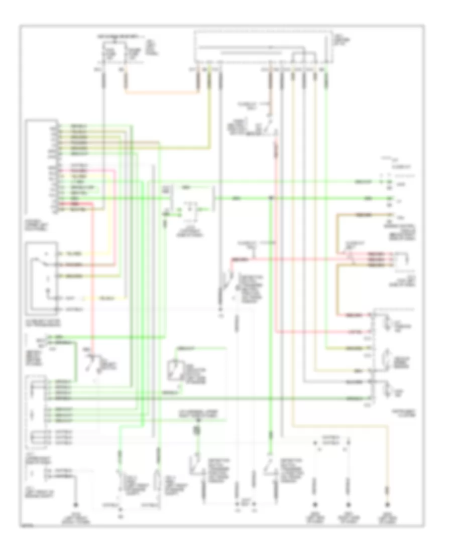
3.4L, A/T Wiring Diagram, with Column Shift for Toyota Tacoma 1997
List of elements for 3.4L, A/T Wiring Diagram, with Column Shift for Toyota Tacoma 1997:
- 2 ind
- A/t oil temperature sensor (on transmission)
- Batt (b+)
- C12
- C13
- Cig fuse 15a
- Cruise control system
- D ind
- D16
- D17
- Data link connector (left side of engine compt)
- E1 (grd)
- E12
- E13
- Ect pwr
- Efi fuse 15a
- Efi relay (on r/b 2)
- Electronic controlled transmission solenoids
- Electronically controlled transmission pattern select switch
- Engine control module (behind right side of dash)
- Engine coolant temperature sensor (on engine)
- F15
- G102 (upper center of left front fender apron)
- G110 (left front of engine)
- G200 (left kick panel)
- Gauge fuse 10a
- Hot at all times
- Hot in run or accy
- Hot in run or start
- I10
- I10 (dash harness, behind right side of dash)
- Idl0
- Ign fuse 7.5a
- Instrument cluster
- J/b 1 (behind dash, left side of steering column)
- J/b 3 (behind dash, above steering column)
- Junction connector 1 (left side of engine compt)
- Junction connector 4 (upper left end of dash)
- Junction connector 8 (right end of dash)
- L ind
- N ind
- No. 1
- No. 2
- No. 3
- O/d main switch
- Od off
- Od1
- Od2
- Oil
- P ind
- Park/neutral position switch (on transmission)
- Pnk
- Pwr
- R ind
- R/b 2 (left side of engine compt)
- Sp1
- Sp2+
- Sp2-
- Speedo
- Stop fuse 15a
- Stoplamp switch (on brake pedal bracket)
- Te1
- Throttle position sensor (on throttle body)
- Thw
- Vcc
- Vehicle speed sensor (for ect) (on transmission)
- Vta
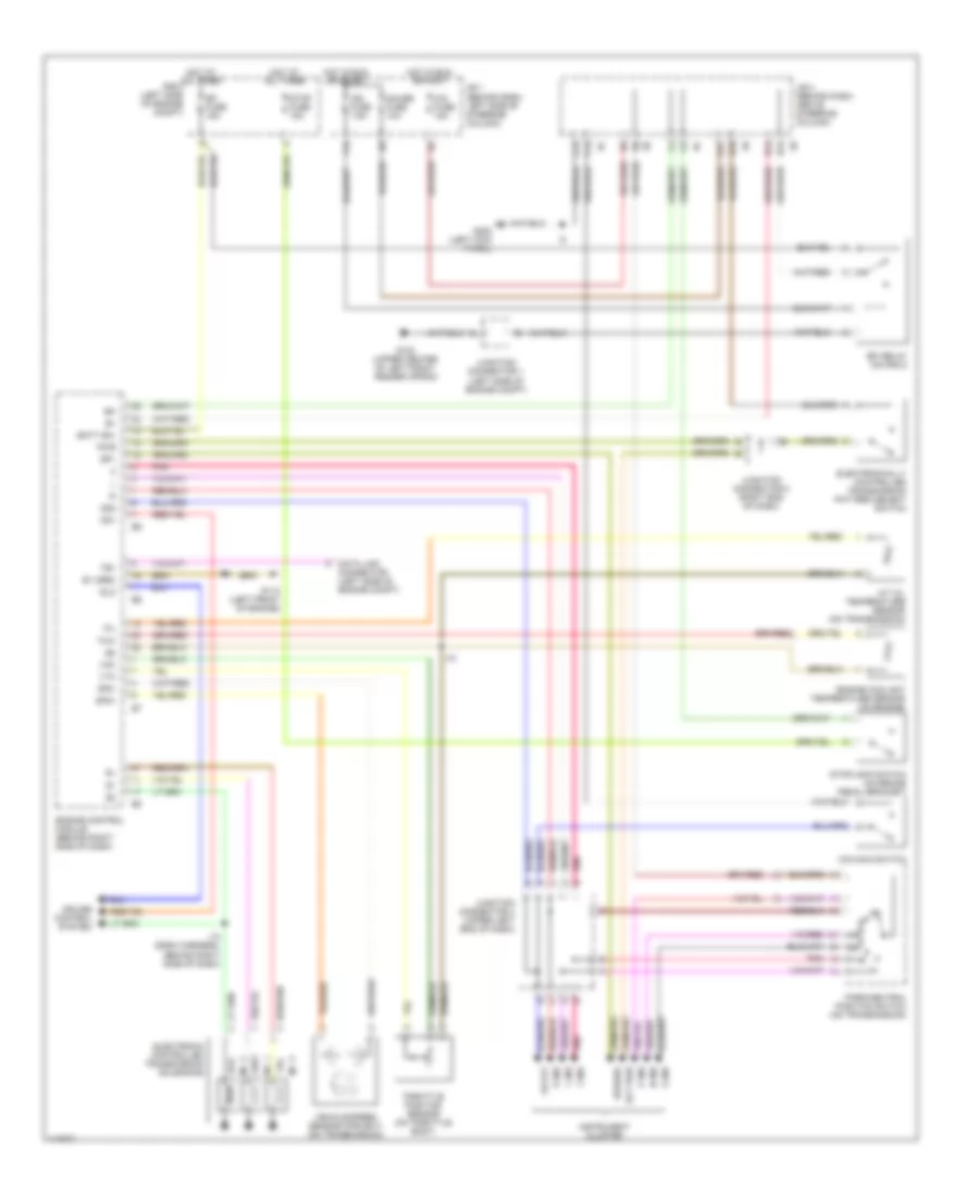
3.4L, A/T Wiring Diagram, with Floor Shift for Toyota Tacoma 1997
List of elements for 3.4L, A/T Wiring Diagram, with Floor Shift for Toyota Tacoma 1997:
- A/t oil temperature sensor (on transmission)
- Batt (b+)
- C11
- C12
- C13
- Cruise control system
- D14
- D16
- D17
- Data link connector (left side of engine compt)
- E1 (grd)
- E12
- E13
- Ect pwr
- Efi fuse 15a
- Efi relay (on r/b 2)
- Electronic controlled transmission solenoids
- Electronically controlled transmission pattern select switch
- Engine control module (behind right side of dash)
- Engine coolant temperature sensor (on engine)
- F15
- G102 (upper center of left front fender apron)
- G110 (left front of engine)
- G200 (left kick panel)
- Gauge fuse 10a
- Hot at all times
- Hot in run or start
- I10
- I10 (dash harness, behind right side of dash)
- Idl0
- Ign fuse 7.5a
- Instrument cluster
- J/b 1 (left kick panel)
- J/b 3 (behind combination meter)
- Junction connector (upper left end of dash)
- Junction connector 1 (left side of engine compt)
- No. 1
- No. 2
- No. 3
- O/d main switch
- Od off
- Od1
- Od2
- Oil
- Oil temp
- Oil-w
- Park/neutral position switch (on transmission)
- Pnk
- Pwr
- Relay block 2 (left side of engine compt)
- Sp1
- Sp2+
- Sp2-
- Speedo
- Stop fuse 15a
- Stoplamp switch (on brake pedal bracket)
- Te1
- Throttle position sensor (on throttle body)
- Thw
- Vcc
- Vehicle speed sensor (for ect) (on transmission)
- Vta
4WD Wiring Diagram, with 2-4 Select Switch for Toyota Tacoma 1997
List of elements for 4WD Wiring Diagram, with 2-4 Select Switch for Toyota Tacoma 1997:
- (i/p harness, upper right side of dash) i10
- 2-4
- 2-4 select motor (on transmission)
- 2-4 select switch
- 4wd
- 4wd ecu (upper left kick panel)
- 4wd fuse 15a
- 4wd ind
- A/t ind switch
- A/t parking ind
- A10
- Abs ecu (below center of dash)
- Add indicator switch (left side of engine)
- B12
- C10
- C12
- C13
- D10
- D12
- D14
- D17
- D19
- Detection switch (transfer l4 position) (on trans- mission)
- Detection switch (transfer neutral position) (on trans- mission)
- Detection switch (transfer position) (on trans- mission)
- Engine control module (behind right side of dash)
- Exi
- Exi3
- F18
- F20
- Floor a/t
- Floor a/t only
- G102 (left front shock tower)
- G201 (right side of dash)
- G202 (left end of dash)
- Gauge fuse 10a
- Gnd
- Hot in run or start
- I10
- Ind
- Instrument cluster
- J/b 1 (left kick panel)
- J/b 3 (center of i/p)
- J/c 1 (left front of engine compt)
- J/c 4 (top left side of dash)
- J/c 6 (top right side of dash)
- J/c 7 (upper right side of dash)
- M/t
- Park/ neutral position switch
- Red
- Rl1
- Rl2
- Spd
- Tfn
- Th+
- Th-
- Vehicle speed sensor
- Vsv 2 (add) (left front of engine compt)
- Vsv 4 (add) (left front of engine compt)
- W/ abs
- W/o abs
4WD Wiring Diagram, without 2-4 Select Switch for Toyota Tacoma 1997
List of elements for 4WD Wiring Diagram, without 2-4 Select Switch for Toyota Tacoma 1997:
- (on trans- mission)
- 2.7l
- 3.4l a/t
- 3.4l m/t
- 4wd
- 4wd control ecu (w/ rear diff lock) (upper left kick panel)
- 4wd fuse 15a
- 4wd ind
- :floor a/t only
- :w/ abs
- :w/ add control relay
- :w/ rear diff lock
- :w/o abs
- :w/o add control relay
- :w/o rear diff lock
- A/t parking ind
- A10
- Abs ecu (below
- Abs ecu (below center of dash)
- Add control relay (upper right kick panel)
- Add indicator switch (left side of engine)
- B12
- C10
- C13
- Center of dash)
- D14
- D17
- D19
- Detection switch (transfer l4 position) (on trans- mission)
- Detection switch (transfer neutral position)
- Detection switch (transfer position) (on trans- mission)
- Engine control module (behind right side of dash)
- Exi
- Exi3
- F18
- F20
- From instrument cluster (diagram 1 of 1)
- G102 (left front shock tower)
- G201 (right side of dash)
- Gauge fuse 10a
- Hot in on or start
- I10
- I10 (i/p harn, upper right side
- Instrument cluster
- J/b 1 (left kick panel)
- J/b 3 (center of i/p)
- J/c 1 (left front of engine compt)
- J/c 6 (top right side of dash)
- J/c 7 (upper right side of dash)
- Of dash)
- Park/neutral position switch (a/t indicator switch) (transmission)
- Tfn
- To add indicator switch (diagram 1 of 1)
- Vsv 2 (add) (left front of engine compt)
- Vsv 4 (add) (left front of engine compt)
Rear Differential Lock Wiring Diagram for Toyota Tacoma 1997
List of elements for Rear Differential Lock Wiring Diagram for Toyota Tacoma 1997:
- (speedometer)
- 3.4l
- 4wd
- 4wd control ecu (upper left kick panel)
- 4wd fuse 15a
- A10
- Abs ecu (below center of dash)
- B12
- C10
- C12
- C13
- D10
- D12
- D15
- D17
- Detection switch (transfer l4 position) (on transmission)
- Except 3.4l
- Exi2
- Exi3
- F18
- F20
- Free
- G201 (right side of dash)
- G202 (left end of dash)
- Gauge fuse 10a
- Gnd
- Hot in on or start
- I10
- Instrument cluster
- Integration relay
- J/b 1 (left kick panel)
- J/b 3 (behind center of i/p)
- J/c 2 (upper left side of dash)
- J/c 5 (top right side of dash)
- J/c 6 (top right side of dash)
- J/c 7 (upper right side of dash)
- Limit switch
- Lock
- Rear differential lock switch
- Rear differential lock detection switch
- Rear differential lock indicator
- Rear differential lock motor
- Rel1
- Rel2
- Rlp
- Spd
- Vehicle speed sensor
- W/ abs
- W/o abs
Transfer Case Wiring Diagram, with 2-4 Select Switch for Toyota Tacoma 1997
List of elements for Transfer Case Wiring Diagram, with 2-4 Select Switch for Toyota Tacoma 1997:
- (i/p harness, upper right side of dash) i10
- 2-4
- 2-4 select motor (on transmission)
- 2-4 select switch
- 4wd
- 4wd ecu (upper left kick panel)
- 4wd fuse 15a
- 4wd ind
- A/t ind switch
- A/t parking ind
- A10
- Abs ecu (below center of dash)
- Add indicator switch (left side of engine)
- B12
- C10
- C12
- C13
- D10
- D12
- D14
- D17
- D19
- Detection switch (transfer l4 position) (on trans- mission)
- Detection switch (transfer neutral position) (on trans- mission)
- Detection switch (transfer position) (on trans- mission)
- Engine control module (behind right side of dash)
- Exi
- Exi3
- F18
- F20
- Floor a/t
- Floor a/t only
- G102 (left front shock tower)
- G201 (right side of dash)
- G202 (left end of dash)
- Gauge fuse 10a
- Gnd
- Hot in run or start
- I10
- Ind
- Instrument cluster
- J/b 1 (left kick panel)
- J/b 3 (center of i/p)
- J/c 1 (left front of engine compt)
- J/c 4 (top left side of dash)
- J/c 6 (top right side of dash)
- J/c 7 (upper right side of dash)
- M/t
- Park/ neutral position switch
- Red
- Rl1
- Rl2
- Spd
- Tfn
- Th+
- Th-
- Vehicle speed sensor
- Vsv 2 (add) (left front of engine compt)
- Vsv 4 (add) (left front of engine compt)
- W/ abs
- W/o abs
Transfer Case Wiring Diagram, without 2-4 Select Switch for Toyota Tacoma 1997
List of elements for Transfer Case Wiring Diagram, without 2-4 Select Switch for Toyota Tacoma 1997:
- (on trans- mission)
- 2.7l
- 3.4l a/t
- 3.4l m/t
- 4wd
- 4wd control ecu (w/ rear diff lock) (upper left kick panel)
- 4wd fuse 15a
- 4wd ind
- :floor a/t only
- :w/ abs
- :w/ add control relay
- :w/ rear diff lock
- :w/o abs
- :w/o add control relay
- :w/o rear diff lock
- A/t parking ind
- A10
- Abs ecu (below
- Abs ecu (below center of dash)
- Add control relay (upper right kick panel)
- Add indicator switch (left side of engine)
- B12
- C10
- C13
- Center of dash)
- D14
- D17
- D19
- Detection switch (transfer l4 position) (on trans- mission)
- Detection switch (transfer neutral position)
- Detection switch (transfer position) (on trans- mission)
- Engine control module (behind right side of dash)
- Exi
- Exi3
- F18
- F20
- From instrument cluster (diagram 1 of 1)
- G102 (left front shock tower)
- G201 (right side of dash)
- Gauge fuse 10a
- Hot in on or start
- I10
- I10 (i/p harn, upper right side
- Instrument cluster
- J/b 1 (left kick panel)
- J/b 3 (center of i/p)
- J/c 1 (left front of engine compt)
- J/c 6 (top right side of dash)
- J/c 7 (upper right side of dash)
- Of dash)
- Park/neutral position switch (a/t indicator switch) (transmission)
- Tfn
- To add indicator switch (diagram 1 of 1)
- Vsv 2 (add) (left front of engine compt)
- Vsv 4 (add) (left front of engine compt)