TRANSMISSION
3.4L
3.4L, 4WD Wiring Diagram for Toyota Tundra Limited 2003

List of elements for 3.4L, 4WD Wiring Diagram for Toyota Tundra Limited 2003:
- (a/t)
- 4wd
- 4wd fuse 20a
- 4wd ind
- A/t
- A/t p ind
- Abs actuator with ecu (right rear of engine compt)
- Acc fuse 15a
- Add actuator (front of engine)
- C11
- C12
- C14
- Combination meter
- Detection switch (4wd position) (transfer case)
- Detection switch (l4 position) (transfer case)
- Detection switch (neutral position) (transfer case)
- Diode (a/t) (behind upper left side of dash)
- Driver side j/b (lower left side of dash)
- Engine control module (behind right side of dash)
- Ex13
- G11
- Gauge fuse 10a
- Hot in on or acc
- Hot in on or start
- J/c 10 (behind upper left side of dash)
- J/c 11 (behind upper right side of dash)
- J/c 12 (behind upper right side of dash)
- J/c 13 (right kick panel)
- J/c 8 (behind upper left side of dash)
- J/c 9 (behind upper left side of dash)
- M/t
- Neutral position switch (part of park/ neutral position switch)
- Red
- Tfn
- Transmission control relay (behind lower right side of dash)
- W/ door lock ctrl
- W/o door lock ctrl
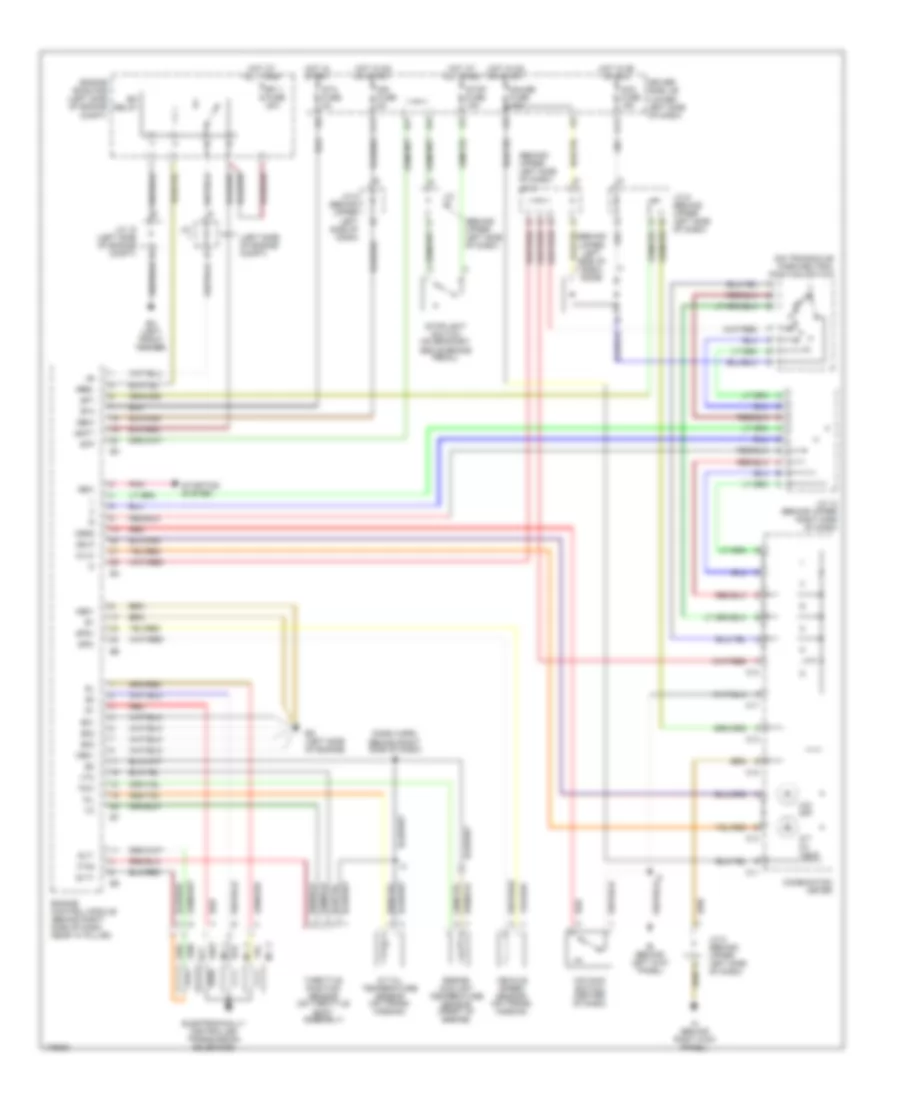
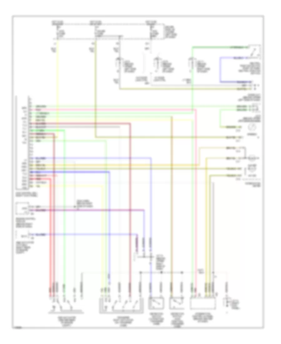
3.4L, A/T Wiring Diagram for Toyota Tundra Limited 2003
List of elements for 3.4L, A/T Wiring Diagram for Toyota Tundra Limited 2003:
- (behind upper left side of dash)
- (behind upper left side of dash) diode
- (behind upper left side of dash) j/c 8
- (dash harn, behind right side of dash) i3
- (left side of engine compt)
- (on transaxle) park/neutral position switch
- A/t oil temp
- A/t oil temperature sensor (on trans- mission)
- Acc fuse 15a
- Batt
- C11
- C12
- C13
- C14
- Combination meter
- Driver side j/b (lower left side of dash)
- E01
- E02
- E03
- Ea (left front fender)
- Ed (left side of engine)
- Efi 1 fuse 20a
- Efi relay
- Electronically controlled transmission solenoids
- Engine control module (behind right side of dash, near "a" pillar)
- Engine coolant temperature sensor (front of engine)
- Engine room r/b (left side of engine compt)
- F11
- G11
- Gauge fuse 10a
- Hot at all times
- Hot in on or acc
- Hot in on or start
- Hot in start
- Ie (behind left kick panel)
- Ign fuse 5a
- Igsw
- Ih (behind right kick panel)
- J/c
- J/c 12 (behind upper right side of dash)
- J/c 18 (left side of engine compt)
- J/c 5 (behind upper left side of dash)
- J/c 8 (behind upper left side of dash)
- J/c 9 (behind upper left side of dash)
- Me01
- Mrel
- No. 1
- No. 2
- No. 3
- Nsw
- O/d main switch (center of dash)
- O/d off
- Odlp
- Odms
- Oil
- Oilw
- Pnk
- Red
- Slt
- Slt+
- Slt-
- Sp1
- Sp2+
- Sp2-
- Sta
- Sta fuse 5a
- Starting system
- Stop fuse 15a
- Stoplight switch (on bracket, above brake pedal)
- Stp
- Throttle position sensor (on throttle body assembly)
- Thw
- Vehicle speed sensor (on trans- mission)
- Vta
- Vta2
4.7L
4.7L, 4WD Wiring Diagram for Toyota Tundra Limited 2003
List of elements for 4.7L, 4WD Wiring Diagram for Toyota Tundra Limited 2003:
- (behind upper right side of dash)
- (dah harn, behind right side of dash) i3
- 2-4
- 4hi ind
- 4lo ind
- 4wd
- 4wd control ecu (right kick panel)
- 4wd fuse 20a
- Abs actuator with ecu (right rear of engine compt)
- Acc fuse 15a
- Add
- Add actuator (center rear of engine compt)
- C11
- C12
- C13
- C14
- Combination meter
- Detection switch (4wd position) (transfer case)
- Detection switch (l4 position) (transfer case)
- Diode (a/t) (behind upper left side of dash)
- Dl1
- Dl2
- Dm1
- Dm2
- Driver side j/b (lower left side of dash)
- Engine control module (behind right side of dash)
- Ex13
- G11
- Gauge fuse 10a
- Gnd
- H-l
- Hot in on or acc
- Hot in on or start
- I24
- Ind1
- Ind2
- Integration control & panel (behind center of dash)
- J/c 11 (behind upper right side of dash)
- J/c 12
- J/c 13 (right kick panel)
- J/c 8 (behind upper left side of dash)
- J/c 9 (behind upper left side of dash)
- Neutral position switch (part of park/ neutral position switch)
- Pnk
- Red
- Spd
- Speedo
- Tl1
- Tl2
- Tl3
- Tm1
- Tm2
- Transfer shift actuator (on transfer case)
- W/ door lock ctrl
- W/o door lock ctrl
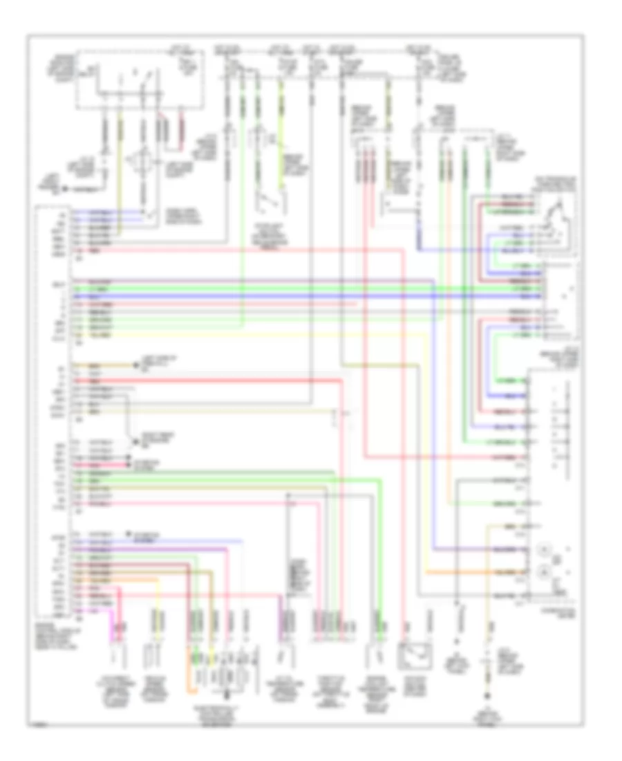
4.7L, A/T Wiring Diagram for Toyota Tundra Limited 2003
List of elements for 4.7L, A/T Wiring Diagram for Toyota Tundra Limited 2003:
- (behind upper left side of dash)
- (behind upper left side of dash) diode
- (behind upper left side of dash) j/c 8
- (behind upper left side of dash) j/c 9
- (dash harn, upper right side of dash)
- (left front fender) ea
- (left side of engine compt)
- (left side of firewall) ec
- (on transaxle) park/neutral position switch
- (right rear of engine) eb
- +b2
- A/t oil temp
- A/t oil temperature sensor (on trans- mission)
- Acc fuse 15a
- Batt
- C11
- C12
- C13
- C14
- Combination meter
- Driver side j/b (lower left side of dash)
- E01
- E02
- E03
- Efi 1 fuse 20a
- Efi relay
- Electronically controlled transmission solenoids
- Engine control module (behind right side of dash, near "a" pillar)
- Engine coolant temperature sensor (right front of engine)
- Engine room r/b (left side of engine compt)
- F11
- G11
- Gauge fuse 10a
- Gw01
- Hot at all times
- Hot in on or acc
- Hot in on or start
- Hot in start
- Ie (behind left kick panel)
- Ign fuse 5a
- Igsw
- Ih (behind right kick panel)
- J/c
- J/c 11 (behind upper right side of dash)
- J/c 12 (behind upper right side of dash)
- J/c 18 (left side of engine compt)
- J/c 5 (behind upper left side of dash)
- J/c 8 (behind upper left side of dash)
- Me01
- Mrel
- Nc0-
- Nco+
- No. 1
- No. 2
- No. 3
- Nsw
- O/d direct clutch speed sensor (left side of trans- mission)
- O/d main switch (center of dash)
- O/d off
- Odlp
- Odms
- Oilw
- Pnk
- Red
- Slt
- Slt+
- Slt-
- Sp2+
- Sp2-
- Spd
- Sta
- Sta fuse 5a
- Star
- Starting system
- Stop fuse 15a
- Stoplight switch (on bracket, above brake pedal)
- Stp
- Stsw
- Thoc
- Throttle position sensor (on throttle body assembly)
- Thw
- Vehicle speed sensor (on trans- mission)
- Vta
- Vta2