TRANSMISSION
4.0L
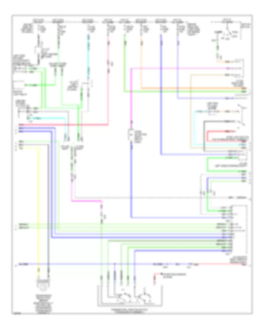
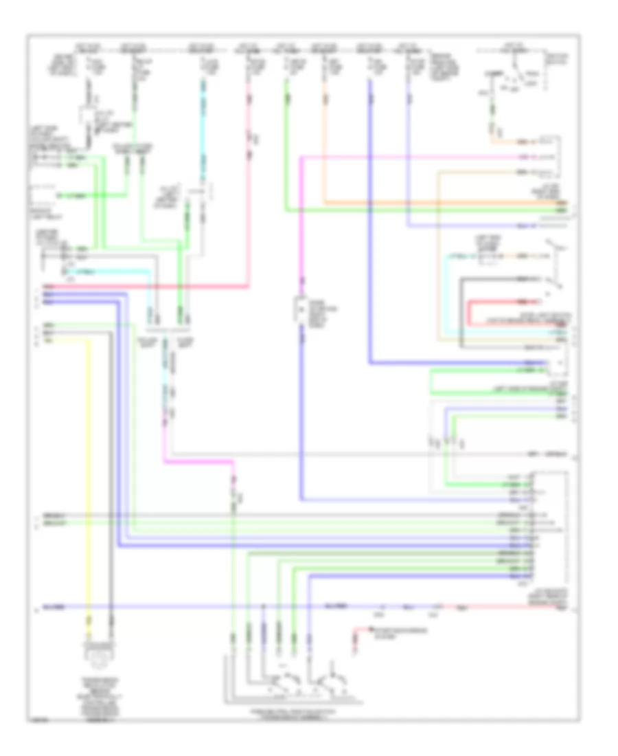
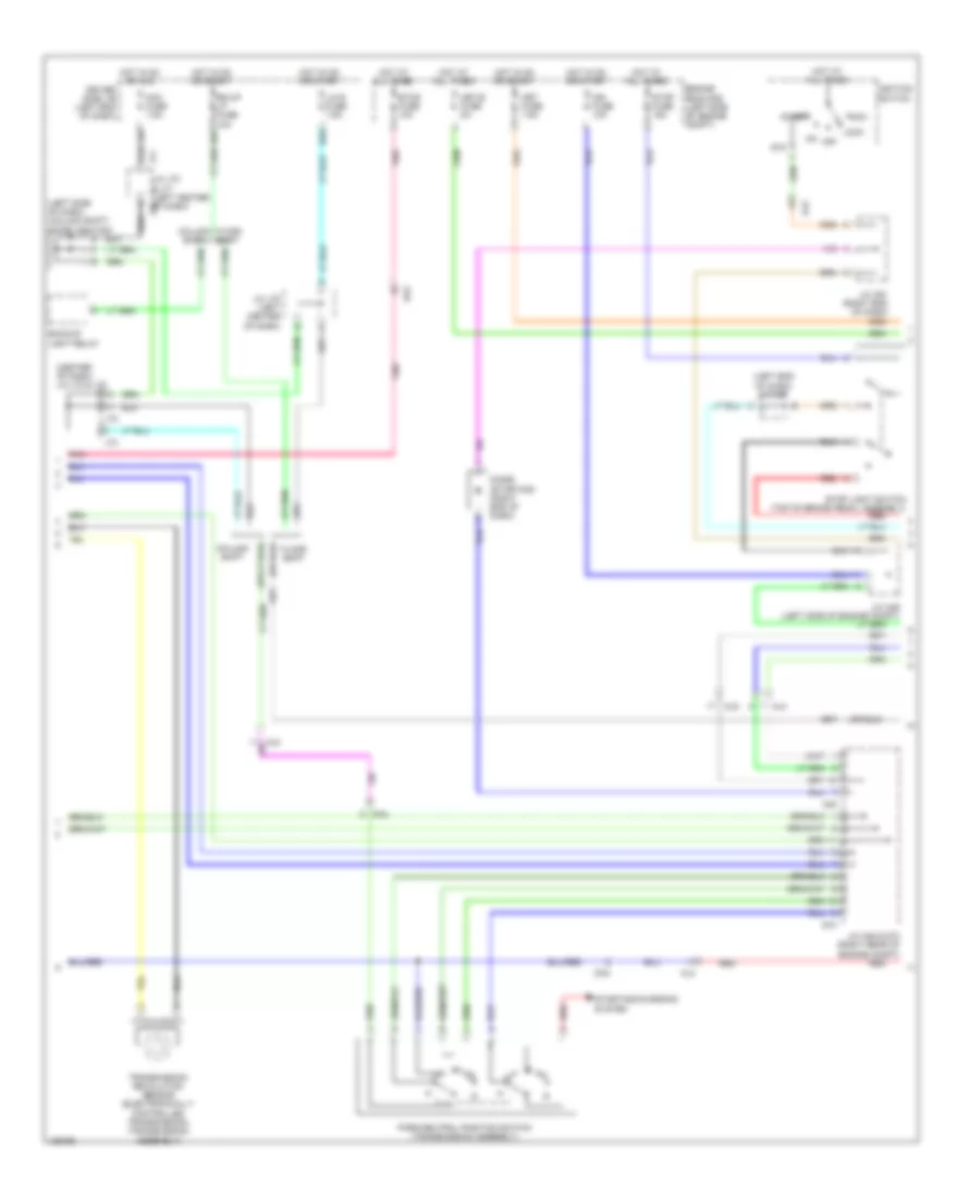
4.0L, A/T Wiring Diagram (1 of 3) for Toyota Tundra Limited 2014

List of elements for 4.0L, A/T Wiring Diagram (1 of 3) for Toyota Tundra Limited 2014:
- +bm
- Automatic transmission
- Crankshaft position sensor (left front of engine)
- D74
- D8 (right rear of engine)
- D9 (right rear of engine)
- E01
- E02
- E03
- E04
- E05
- Engine control module (right rear of engine compt)
- Engine coolant temperature sensor (rear of right cylinder bank)
- Eta
- Ethw
- Ge01
- J/c d71 (right rear of engine compt)
- Me01
- Nca
- Ne+
- Ne-
- Nsw
- Nt+
- Nt-
- Pnk
- Red
- Red sl1+
- Sl1+
- Sl1-
- Sl2+
- Sl2-
- Slt+
- Slt-
- Slu+
- Slu-
- Sp2+
- Sp2-
- Star
- Tho1
- Tho2
- Throttle position sensor (on throttle body)
- Thw
- Transmission revolution sensor (turbine) (in transmission)
- Vcta
- Vta
- Vta1
- Vta2
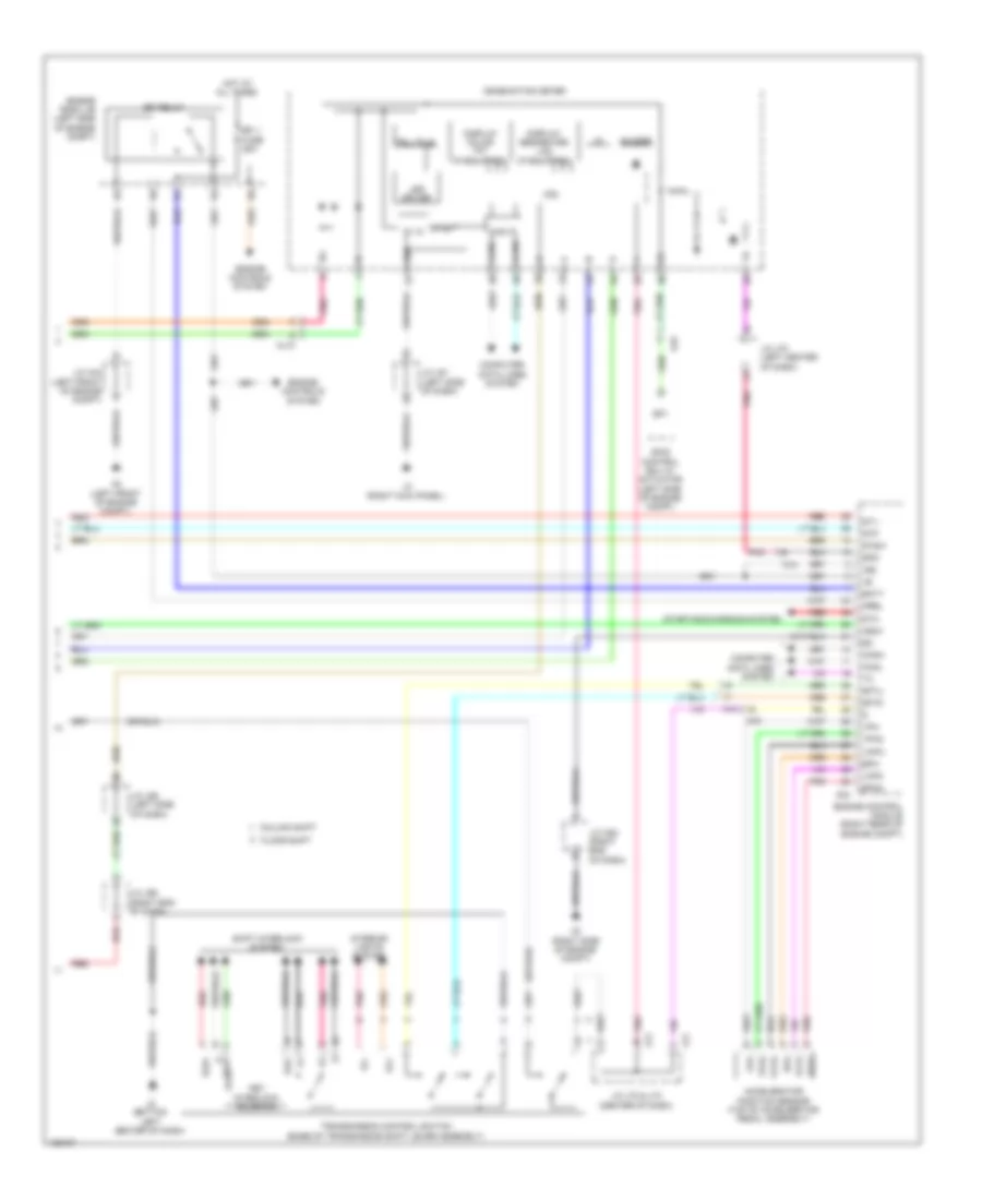
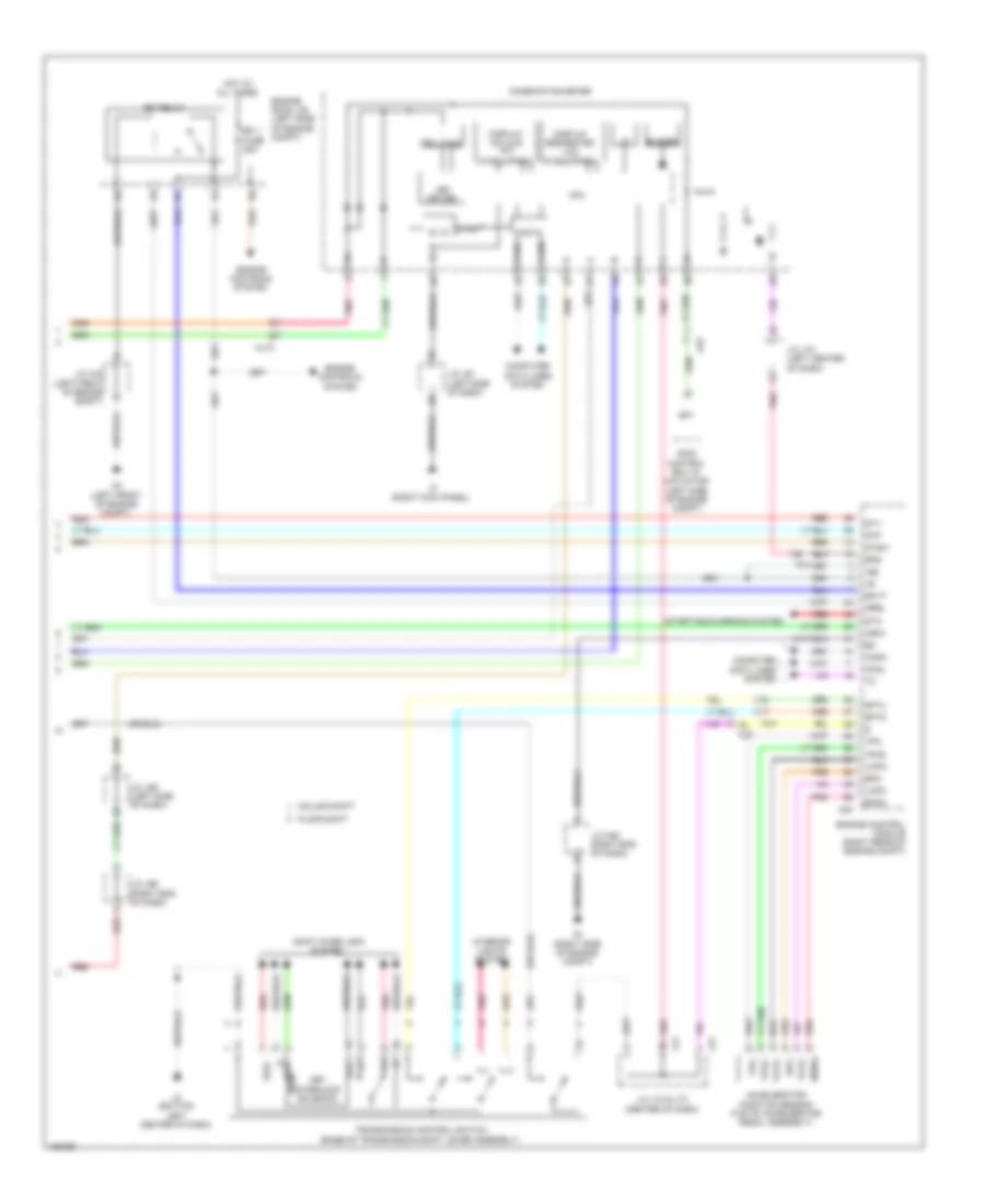
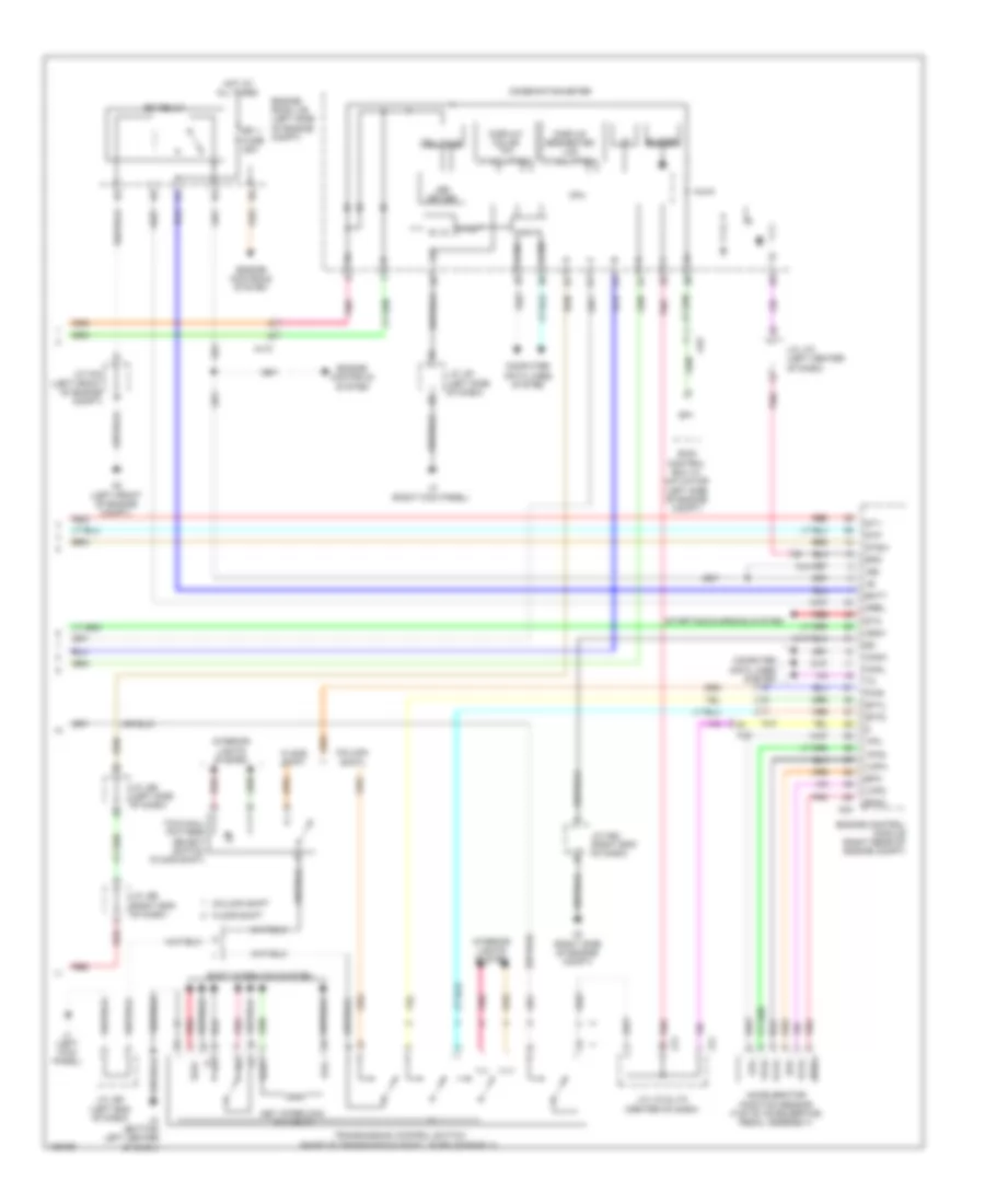
4.0L, A/T Wiring Diagram (2 of 3) for Toyota Tundra Limited 2014
List of elements for 4.0L, A/T Wiring Diagram (2 of 3) for Toyota Tundra Limited 2014:
- (center of dash) j/c j72 & j73
- (left end of dash) j/c a50
- (left side of dash) (column shift) diode (ignition)
- A45
- Acc
- Acc fuse 7.5a
- Aj2
- Aj3
- Aj4
- Aj5
- Backup light relay
- Bk/up lp fuse 10a
- Column shift
- D55
- D65
- D73
- Da2
- Da4
- Diode (starting) (right end of dash)
- Driver side j/b (left end of dash)
- Engine room r/b (left side of engine compt)
- Etcs fuse 10a
- Floor shift
- Hot at all times
- Hot in on or acc
- Hot in on or start
- Ign fuse 10a
- Ignition switch
- J/c a45 & d73 (right rear of engine compt) red
- J/c a49 (left side of engine compt)
- J/c a51 (right end of dash)
- J/c j70 & j71 (left center j70 of dash)
- J/c j70 (left center of dash)
- J71
- J72
- J73
- Lh-ig fuse 7.5a
- Lock
- Met fuse 7.5a
- Met-b fuse 5a
- Off
- Park/neutral position switch (transmission assembly)
- Pnk
- Red
- St2
- Start
- Starting/charging system
- Stop fuse 15a
- Stop light switch (top of brake pedal assembly)
- Transmission revolution sensor (electronically controlled transmission) (transmission assembly)
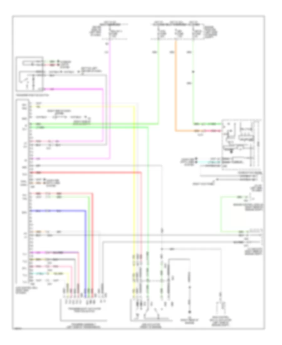
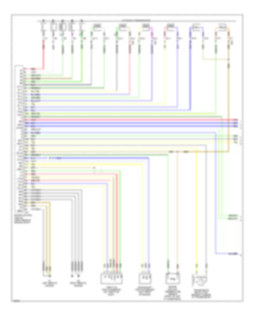
4.0L, A/T Wiring Diagram (3 of 3) for Toyota Tundra Limited 2014
List of elements for 4.0L, A/T Wiring Diagram (3 of 3) for Toyota Tundra Limited 2014:
- +b2
- 5v ic
- 5v+b
- A2 (left front of engine compt)
- A24
- A3 (right side of engine compt)
- Accelerator position sensor (top of accelerator pedal assembly)
- Aj10
- Aj4
- Aj5
- Aj9
- Batt
- Buzzer
- Can if
- Canh
- Canl
- Column shift
- Combination meter
- Computer data lines system
- Cpu
- Display color tft (if equipped)
- Display segmented lcd (if equipped)
- Efi 1 fuse 25a
- Efi relay
- Engine control module (right rear of engine compt)
- Engine controls system
- Engine room j/b (left side of engine compt)
- Epa
- Epa2
- Floor shift
- Hot at all times
- I/f
- Ig+
- Igsw
- Ill+
- Ill-
- Interior lights system
- J/c a44 (left front of engine compt)
- J/c a52 (right end of dash)
- J/c j61 (left side of dash)
- J/c j65 (left side of dash)
- J/c j66 (right end of dash)
- J/c j70 (left center of dash)
- J/c j72 & j73 (center of dash)
- J2 (bottom left center of dash)
- J3 (right kick panel)
- J72
- J73
- Key interlock solenoid
- Kls+ e
- Kls-
- Led driver
- Mrel
- Pnk
- Red
- Sftd
- Sftu
- Shift interlock system
- Skid control ecu w/ actuator (left side of engine compt)
- Sls+
- Sp1
- Spd
- St1-
- Sta
- Starting/charging system
- Stp
- Stsw
- Telltale
- Transmission control switch (base of transmission shift lever assembly)
- Vcp2
- Vcpa
- Vpa
- Vpa2
4.6L
4.6L, 4WD Wiring Diagram for Toyota Tundra Limited 2014
List of elements for 4.6L, 4WD Wiring Diagram for Toyota Tundra Limited 2014:
- (bottom left center of dash) j2
- (right end of dash) j/c a52
- (right side of engine compt)
- 2-4
- 4wd control ecu (right end of dash)
- 4wd fuse 30a
- 5v ic
- A24
- A25
- A26
- A45
- Add
- Add actuator (front of engine)
- Aj10
- Aj3
- Buzzer
- Can i/f
- Canh
- Canl
- Combination meter
- Computer data lines system
- Cpu
- D3 (right rear of engine)
- D67
- D68
- D70
- D73
- Da1
- Da4
- Dg1
- Dl1
- Dl2
- Dm1
- Dm2
- Driver side j/b (left end of dash)
- Ecu-ig1 3 fuse 7.5a
- Engine control module (right rear of engine compt)
- Engine room r/b (left side of engine compt)
- Ex12
- Gnd
- Gtl
- Hot at all times
- Hot w/ ig 2 relay energized
- Hot w/ ig1 relay energized
- I/f
- Ig+
- Ill+
- Ill-
- Interior lights system
- J/c a45 & d73 (right rear of engine compt)
- J/c j61 (left side of dash)
- J3 (right kick panel)
- Led driver
- Met fuse 7.5a
- Met-b fuse 5a
- Pnk
- Red
- Scc
- Skid control ecu w/ actuator (left side of engine compt)
- Telltale
- Tl1
- Tl2
- Tl3
- Tl4
- Tm1
- Tm2
- Transfer assembly (left side of transmission)
- Transfer position switch
- Transfer shift actuator position switch
4.6L, A/T Wiring Diagram (1 of 3) for Toyota Tundra Limited 2014
List of elements for 4.6L, A/T Wiring Diagram (1 of 3) for Toyota Tundra Limited 2014:
- +bm
- Automatic transmission
- Crankshaft position sensor (left front of engine)
- D1 (left rear of engine)
- D2 (right rear of engine)
- D74
- E01
- E02
- E03
- E04
- E05
- Engine control module (right rear of engine compt)
- Engine coolant temperature sensor (front of left cylinder bank)
- Eta
- Ge01
- Me01
- Ne+
- Ne-
- Nsw
- Nt+
- Nt-
- Pnk
- Red
- Red sl1+
- Sl1+
- Sl1-
- Sl2+
- Sl2-
- Slt+
- Slt-
- Slu+
- Slu-
- Sp2+
- Sp2-
- Star
- Tho1
- Tho2
- Throttle position sensor (on throttle body)
- Thw
- Transmission revolution sensor (turbine) (in transmission)
- Vcta
- Vcv2
- Vta
- Vta1
- Vta2
4.6L, A/T Wiring Diagram (2 of 3) for Toyota Tundra Limited 2014
List of elements for 4.6L, A/T Wiring Diagram (2 of 3) for Toyota Tundra Limited 2014:
- (center of dash) j/c j72 & j73
- (left end of dash) j/c a50
- (left side of dash) (column shift) diode (ignition)
- A45
- Acc
- Acc fuse 7.5a
- Aj2
- Aj3
- Aj4
- Aj5
- Backup light relay
- Bk/up lp fuse 10a
- Column shift
- D55
- D65
- D73
- Da2
- Da4
- Diode (starting) (right end of dash)
- Driver side j/b (left end of dash)
- Engine room r/b (left side of engine compt)
- Etcs fuse 10a
- Floor shift
- Hot at all times
- Hot in on or acc
- Hot in on or start
- Ign fuse 10a
- Ignition switch
- J/c a45 & d73 (right rear of engine compt) red
- J/c a51 (right end of dash)
- J/c j70 & j71 (left center j70 of dash)
- J/c j70 (left center of dash)
- J71
- J72
- J73
- Lh-ig fuse 7.5a
- Lock
- Met fuse 7.5a
- Met-b fuse 5a
- Off
- Park/neutral position switch (transmission assembly)
- Pnk
- Red
- St2
- Start
- Starting/charging system
- Stop fuse 15a
- Stop light switch (top of brake pedal assembly)
- Transmission revolution sensor (electronically controlled transmission) (transmission assembly)
4.6L, A/T Wiring Diagram (3 of 3) for Toyota Tundra Limited 2014
List of elements for 4.6L, A/T Wiring Diagram (3 of 3) for Toyota Tundra Limited 2014:
- +b2
- 5v ic
- 5v+b
- A2 (left front of engine compt)
- A24
- A3 (right side of engine compt)
- Accelerator position sensor (top of accelerator pedal assembly)
- Aj10
- Aj4
- Aj5
- Aj9
- Batt
- Buzzer
- Can if
- Canh
- Canl
- Column shift
- Combination meter
- Computer data lines system
- Cpu
- Display colour tft (if equipped)
- Display segmented lcd (if equipped)
- E kls+
- Efi 1 fuse 25a
- Efi relay
- Engine control module (right rear of engine compt)
- Engine controls system
- Engine room j/b (left side of engine compt)
- Epa
- Epa2
- Floor shift
- Hot at all times
- I/f
- Ig+
- Igsw
- Ill+
- Ill-
- Interior lights system
- J/c a44 (left front of engine compt)
- J/c a52 (right end of dash)
- J/c j61 (left side of dash)
- J/c j65 (left side of dash)
- J/c j66 (right end of dash)
- J/c j70 (left center of dash)
- J/c j72 & j73 (center of dash)
- J2 (bottom left center of dash)
- J3 (right kick panel)
- J72
- J73
- Key interlock solenoid
- Kls-
- Led driver
- Mrel
- Pnk
- Red
- Sftd
- Sftu
- Shift inter lock system
- Skid control ecu w/ actuator (left side of engine compt)
- Sls+
- Sp1
- Spd
- St1-
- Sta
- Starting/charging system
- Stp
- Stsw
- Telltale
- Transmission control switch (base of transmission shift lever assembly)
- Vcp2
- Vcpa
- Vpa
- Vpa2
5.7L
5.7L, 4WD Wiring Diagram for Toyota Tundra Limited 2014
List of elements for 5.7L, 4WD Wiring Diagram for Toyota Tundra Limited 2014:
- (bottom left center of dash) j2
- (right end of dash) j/c a52
- (right side of engine compt)
- 2-4
- 4wd control ecu (right end of dash)
- 4wd fuse 30a
- 5v ic
- A24
- A25
- A26
- A45
- Add
- Add actuator (front of engine)
- Aj10
- Aj3
- Buzzer
- Can i/f
- Canh
- Canl
- Combination meter
- Computer data lines system
- Cpu
- D3 (right rear of engine)
- D67
- D68
- D70
- D73
- Da1
- Da4
- Dg1
- Dl1
- Dl2
- Dm1
- Dm2
- Driver side j/b (left end of dash)
- Ecu-ig1 3 fuse 7.5a
- Engine control module (right rear of engine compt)
- Engine room r/b (left side of engine compt)
- Ex12
- Gnd
- Gtl
- Hot at all times
- Hot w/ ig 2 relay energized
- Hot w/ ig1 relay energized
- I/f
- Ig+
- Ill+
- Ill-
- Interior lights system
- J/c a45 & d73 (right rear of engine compt)
- J/c j61 (left side of dash)
- J3 (right kick panel)
- Led driver
- Met fuse 7.5a
- Met-b fuse 5a
- Pnk
- Red
- Scc
- Skid control ecu w/ actuator (left side of engine compt)
- Telltale
- Tl1
- Tl2
- Tl3
- Tl4
- Tm1
- Tm2
- Transfer assembly (left side of transmission)
- Transfer position switch
- Transfer shift actuator position switch
5.7L, A/T Wiring Diagram (1 of 3) for Toyota Tundra Limited 2014
List of elements for 5.7L, A/T Wiring Diagram (1 of 3) for Toyota Tundra Limited 2014:
- +bm
- Automatic transmission
- Crankshaft position sensor (left front of engine)
- D1 (left rear of engine)
- D2 (right rear of engine)
- D63
- D64
- D74
- E01
- E02
- E03
- E04
- E05
- Engine control module (right rear of engine compt)
- Engine coolant temperature sensor (front of left cylinder bank)
- Eta
- Etha
- Ge01
- Me01
- Ne+
- Ne-
- Nsw
- Nt+
- Nt-
- Pnk
- Red
- Red sl1+
- Sl1+
- Sl1-
- Sl2+
- Sl2-
- Slt+
- Slt-
- Slu+
- Slu-
- Sp2+
- Sp2-
- Star
- Tho1
- Tho2
- Throttle position sensor (on throttle body)
- Thw
- Transmission revolution sensor (turbine) (in transmission)
- Vcta
- Vcv2
- Vta
- Vta1
- Vta2
5.7L, A/T Wiring Diagram (2 of 3) for Toyota Tundra Limited 2014
List of elements for 5.7L, A/T Wiring Diagram (2 of 3) for Toyota Tundra Limited 2014:
- (center of dash) j/c j72 & j73
- (left end of dash) j/c a50
- (left side of dash) (column shift) diode (ignition)
- A45
- Acc
- Acc fuse 7.5a
- Aj3
- Aj4
- Aj5
- Backup light relay
- Bk/up lp fuse 10a
- Column shift
- D55
- D65
- D73
- Da2
- Da4
- Diode (starting) (right end of dash)
- Driver side j/b (left end of dash)
- Engine room r/b (left side of engine compt)
- Etcs fuse 10a
- Floor shift
- Hot at all times
- Hot in on or acc
- Hot in on or start
- Ign fuse 10a
- Ignition switch
- J/c a45 & d73 (right rear of engine compt)
- J/c a49 (left side of engine compt)
- J/c j70 & j71 (left center j70 of dash)
- J/c j70 (left center of dash)
- J71
- J72
- J73
- Lh-ig fuse 7.5a
- Lock
- Met fuse 7.5a
- Met-b fuse 5a
- Off
- Park/neutral position switch (transmission assembly)
- Pnk
- Red
- St2
- Start
- Starting/charging system
- Stop fuse 15a
- Stop light switch (top of brake pedal assembly)
- Transmission revolution sensor (electronically controlled transmission) (transmission assembly)
5.7L, A/T Wiring Diagram (3 of 3) for Toyota Tundra Limited 2014
List of elements for 5.7L, A/T Wiring Diagram (3 of 3) for Toyota Tundra Limited 2014:
- (bottom left center of dash)
- +b2
- 5v ic
- 5v+b
- A2 (left front of engine compt)
- A24
- A3 (right side of engine compt)
- Accelerator position sensor (top of accelerator pedal assembly)
- Aj10
- Aj4
- Aj5
- Aj9
- Batt
- Buzzer
- Can if
- Canh
- Canl
- Column shift
- Combination meter
- Computer data lines system
- Cpu
- Display color tft (if equipped)
- Display segmented lcd (if equipped)
- Efi 1 fuse 25a
- Efi relay
- Engine control module (right rear of engine compt)
- Engine controls system
- Engine room j/b (left side of engine compt)
- Epa
- Epa2
- Floor shift
- Hot at all times
- I/f
- Ig+
- Igsw
- Ill+
- Ill-
- Interior lights system
- J/c a44 (left front of engine compt)
- J/c a52 (right end of dash)
- J/c j60 (left end of dash)
- J/c j61 (left side of dash)
- J/c j65 (left side of dash)
- J/c j66 (right end of dash)
- J/c j70 (left center of dash)
- J/c j72 & j73 (center of dash)
- J1 (left kick panel)
- J3 (right kick panel)
- J72
- J73
- Key interlock solenoid
- Kls+
- Kls-
- Led driver
- Mrel
- P1 e
- Pnk
- Pwr
- Red
- Sftd
- Sftu
- Shift interlock system
- Skid control ecu w/ actuator (left side of engine compt)
- Sls+
- Sp1
- Spd
- St1-
- Sta
- Starting/charging system
- Stp
- Stsw
- Telltale
- Tow/haul pattern select switch (floor shift)
- Transmission control switch (base of transmission shift lever assembly)
- Vcp2
- Vcpa
- Vpa
- Vpa2
5.7L FLEX FUEL
5.7L Flex Fuel, 4WD Wiring Diagram for Toyota Tundra Limited 2014
List of elements for 5.7L Flex Fuel, 4WD Wiring Diagram for Toyota Tundra Limited 2014:
- (bottom left center of dash) j2
- (right end of dash) j/c a52
- (right side of engine compt)
- 2-4
- 4wd control ecu (right end of dash)
- 4wd fuse 30a
- 5v ic
- A24
- A25
- A26
- A45
- Add
- Add actuator (front of engine)
- Aj10
- Aj3
- Buzzer
- Can i/f
- Canh
- Canl
- Combination meter
- Computer data lines system
- Cpu
- D3 (right rear of engine)
- D67
- D68
- D70
- D73
- Da1
- Da4
- Dg1
- Dl1
- Dl2
- Dm1
- Dm2
- Driver side j/b (left end of dash)
- Ecu-ig1 3 fuse 7.5a
- Engine control module (right rear of engine compt)
- Engine room r/b (left side of engine compt)
- Ex12
- Gnd
- Gtl
- Hot at all times
- Hot w/ ig 2 relay energized
- Hot w/ ig1 relay energized
- I/f
- Ig+
- Ill+
- Ill-
- Interior lights system
- J/c a45 & d73 (right rear of engine compt)
- J/c j61 (left side of dash)
- J3 (right kick panel)
- Led driver
- Met fuse 7.5a
- Met-b fuse 5a
- Pnk
- Red
- Scc
- Skid control ecu w/ actuator (left side of engine compt)
- Telltale
- Tl1
- Tl2
- Tl3
- Tl4
- Tm1
- Tm2
- Transfer assembly (left side of transmission)
- Transfer position switch
- Transfer shift actuator position switch
5.7L Flex Fuel, A/T Wiring Diagram (1 of 3) for Toyota Tundra Limited 2014
List of elements for 5.7L Flex Fuel, A/T Wiring Diagram (1 of 3) for Toyota Tundra Limited 2014:
- +bm
- Automatic transmission
- Crankshaft position sensor (left front of engine)
- D1 (left rear of engine)
- D2 (right rear of engine)
- D63
- D64
- D74
- E01
- E02
- E03
- E04
- E05
- Engine control module (right rear of engine compt)
- Engine coolant temperature sensor (front of left cylinder bank)
- Eta
- Etha
- Ge01
- Me01
- Ne+
- Ne-
- Nsw
- Nt+
- Nt-
- Pnk
- Red
- Red sl1+
- Sl1+
- Sl1-
- Sl2+
- Sl2-
- Slt+
- Slt-
- Slu+
- Slu-
- Sp2+
- Sp2-
- Star
- Tho1
- Tho2
- Throttle position sensor (on throttle body)
- Thw
- Transmission revolution sensor (turbine) (in transmission)
- Vcta
- Vcv2
- Vta
- Vta1
- Vta2
5.7L Flex Fuel, A/T Wiring Diagram (2 of 3) for Toyota Tundra Limited 2014
List of elements for 5.7L Flex Fuel, A/T Wiring Diagram (2 of 3) for Toyota Tundra Limited 2014:
- (center of dash) j/c j72 & j73
- (left end of dash) j/c a50
- (left side of dash) (column shift) diode (ignition)
- A45
- Acc
- Acc fuse 7.5a
- Aj3
- Aj4
- Aj5
- Backup light relay
- Bk/up lp fuse 10a
- Column shift
- D55
- D65
- D73
- Da2
- Da4
- Diode (starting) (right end of dash)
- Driver side j/b (left end of dash)
- Engine room r/b (left side of engine compt)
- Etcs fuse 10a
- Floor shift
- Hot at all times
- Hot in on or acc
- Hot in on or start
- Ign fuse 10a
- Ignition switch
- J/c a45 & d73 (right rear of engine compt)
- J/c a49 (left side of engine compt)
- J/c j70 & j71 (left center j70 of dash)
- J/c j70 (left center of dash)
- J71
- J72
- J73
- Lh-ig fuse 7.5a
- Lock
- Met fuse 7.5a
- Met-b fuse 5a
- Off
- Park/neutral position switch (transmission assembly)
- Pnk
- Red
- St2
- Start
- Starting/charging system
- Stop fuse 15a
- Stop light switch (top of brake pedal assembly)
- Transmission revolution sensor (electronically controlled transmission) (transmission assembly)
5.7L Flex Fuel, A/T Wiring Diagram (3 of 3) for Toyota Tundra Limited 2014
List of elements for 5.7L Flex Fuel, A/T Wiring Diagram (3 of 3) for Toyota Tundra Limited 2014:
- (bottom left center of dash)
- +b2
- 5v ic
- 5v+b
- A2 (left front of engine compt)
- A24
- A3 (right side of engine compt)
- Accelerator position sensor (top of accelerator pedal assembly)
- Aj10
- Aj4
- Aj5
- Aj9
- Batt
- Buzzer
- Can if
- Canh
- Canl
- Column shift
- Combination meter
- Computer data lines system
- Cpu
- Display color tft (if equipped)
- Display segmented lcd (if equipped)
- Efi 1 fuse 25a
- Efi relay
- Engine control module (right rear of engine compt)
- Engine controls system
- Engine room j/b (left side of engine compt)
- Epa
- Epa2
- Floor shift
- Hot at all times
- I/f
- Ig+
- Igsw
- Ill+
- Ill-
- Interior lights system
- J/c a44 (left front of engine compt)
- J/c a52 (right end of dash)
- J/c j60 (left end of dash)
- J/c j61 (left side of dash)
- J/c j65 (left side of dash)
- J/c j66 (right end of dash)
- J/c j70 (left center of dash)
- J/c j72 & j73 (center of dash)
- J1 (left kick panel)
- J3 (right kick panel)
- J72
- J73
- Key interlock solenoid
- Kls+
- Kls-
- Led driver
- Mrel
- P1 e
- Pnk
- Pwr
- Red
- Sftd
- Sftu
- Shift interlock system
- Skid control ecu w/ actuator (left side of engine compt)
- Sls+
- Sp1
- Spd
- St1-
- Sta
- Starting/charging system
- Stp
- Stsw
- Telltale
- Tow/haul pattern select switch (floor shift)
- Transmission control switch (base of transmission shift lever assembly)
- Vcp2
- Vcpa
- Vpa
- Vpa2