TRANSMISSION
3.4L
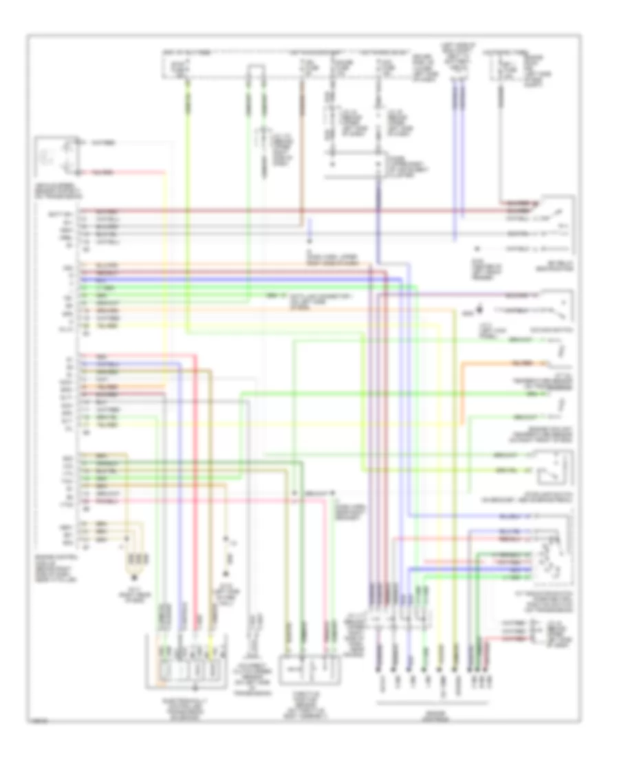
3.4L, 4WD Wiring Diagram for Toyota Tundra SR5 2000

List of elements for 3.4L, 4WD Wiring Diagram for Toyota Tundra SR5 2000:
- (behind right side of dash) j/c 12
- 4wd
- 4wd fuse 20a
- 4wd ind
- A/t p ind
- Abs actuator with ecu (right rear of engine compt)
- Acc fuse 15a
- Add actuator (left side of trans)
- C11
- C14
- California
- California with a/t
- Combination meter
- Detection switch (4wd position) (transfer case)
- Detection switch (l4 position) (transfer case)
- Detection switch (neutral position) (transfer case)
- Didoe (a/t) (behind center of dash)
- Driver side j/b (lower left side of dash)
- Engine control module (behind right side of dash)
- Ex1
- Ex13
- Except california
- Except california with a/t
- G11
- G203
- Gauge fuse 10a
- Hot in on or acc
- Hot in on or start
- J/c 10 (behind center of dash)
- J/c 13 (right kick panel)
- J/c 6 (behind center of dash)
- J/c 8 (behind center of dash)
- J/c 9 (behind center of dash)
- Neutral position switch (part of park/ neutral position switch)
- Red
- Tfn
- Transmission control relay (at right kick panel)
- W/ abs
- W/ power mirrors
- W/o abs
- W/o power mirrors
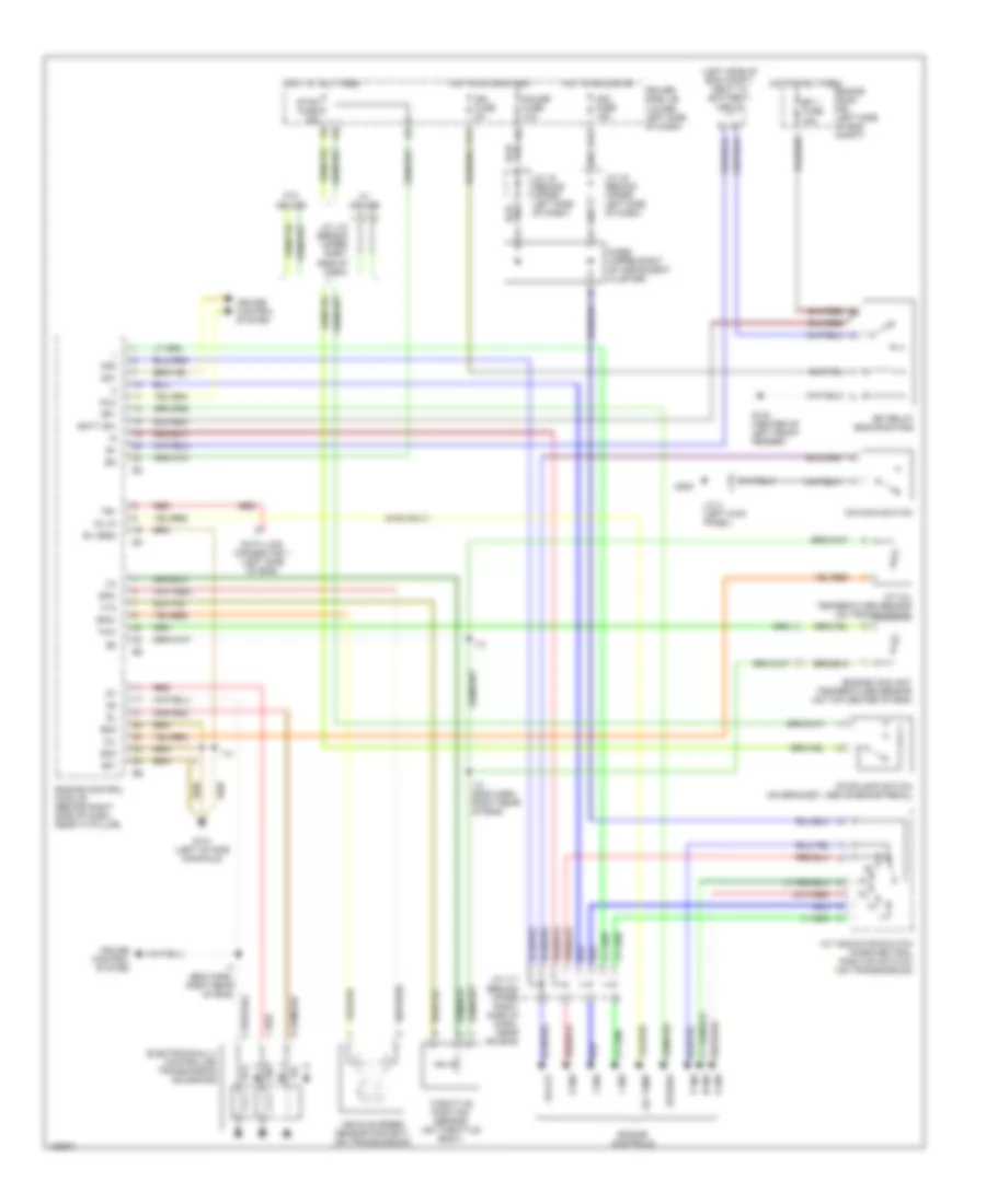
3.4L, A/T Wiring Diagram, California for Toyota Tundra SR5 2000
List of elements for 3.4L, A/T Wiring Diagram, California for Toyota Tundra SR5 2000:
- (left side of eng compt, next to battery) j/c j1
- 2 ind
- A/t indicator switch (park/neutral position switch) (on transmission)
- A/t oil temperature sensor (on transmission)
- Acc fuse 15a
- Batt (b+)
- Cruise control system
- D ind
- Data link connector 1 (left side of eng)
- Diode (upper right of instrument cluster)
- Driver side j/b (lower left side of dash)
- E01
- E05
- E1 (grd)
- Efi 1 fuse 15a
- Efi relay (eng room r/b)
- Electronically controlled transmission solenoids
- Engine control module (behind right side of dash, near "a" pillar)
- Engine controls
- Engine coolant temperature sensor (on top center of eng)
- Engine room r/b (left side of eng compt)
- Eo2
- Eo3
- F11
- G100 (center of left front fender)
- G11
- G131 (left intake manifold)
- G200
- Gauge fuse 10a
- Hot at all times
- Hot in acc or on
- Hot in on or start
- I13
- I13 (eng harn, right rear of eng)
- I14
- I7 (eng harn, right rear of eng)
- Idl0
- Ign fuse 5a
- Igsw
- J/c 3 (left kick panel)
- J/c j11 (behind upper right side of dash, near air bag)
- J/c j12 (behind upper right side of dash)
- J/c j8 (behind upper left side of dash)
- J/c j9 (behind upper left side of dash)
- L ind
- Mrel
- N ind
- No. 1
- No. 2
- No. 3
- O/d main switch
- Od off
- Od1
- Od2
- Oil
- Oil temp
- Oil-w
- P ind
- R ind
- Red
- Sp1
- Sp2+
- Sp2-
- Speedo
- Stop fuse 15a
- Stoplamp switch (on bracket, above brake pedal)
- Te1
- Throttle position sensor (on throttle body)
- Thw
- Vcc
- Vehicle speed sensor (for ect) (on transmission)
- Vta
- W/ cruise
- W/o cruise
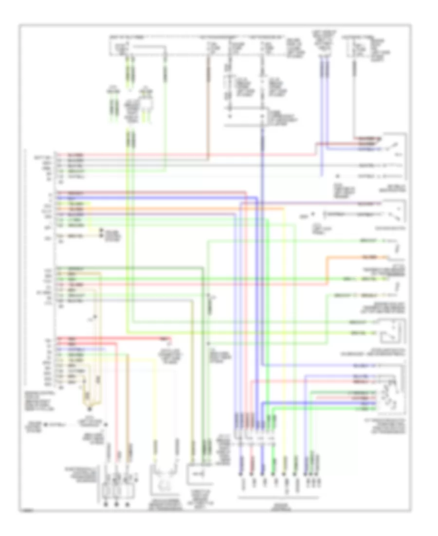
3.4L, A/T Wiring Diagram, Except California for Toyota Tundra SR5 2000
List of elements for 3.4L, A/T Wiring Diagram, Except California for Toyota Tundra SR5 2000:
- (4wd only)
- (left side of eng compt, next to battery) j/c j1
- 2 ind
- A/t indicator switch (park/neutral position switch) (on transmission)
- A/t oil temperature sensor (on transmission)
- Acc fuse 15a
- Batt (b+)
- Cruise control system
- D ind
- Data link connector 1 (left side of eng)
- Diode (upper right of instrument cluster)
- Driver side j/b (lower left side of dash)
- E01
- E1 (grd)
- Efi 1 fuse 15a
- Efi relay (eng room r/b)
- Electronically controlled transmission solenoids
- Engine control module (behind right side of dash, near "a" pillar)
- Engine controls
- Engine coolant temperature sensor (on top center of eng)
- Engine room r/b (left side of eng compt)
- Eo2
- Eo3
- F11
- G100 (center of left front fender)
- G11
- G131 (left intake manifold)
- G200
- Gauge fuse 10a
- Hot at all times
- Hot in acc or on
- Hot in on or start
- I13
- I13 (eng harn, right rear of eng)
- I14
- I7 (eng harn, right rear of eng)
- Idl0
- Ign fuse 5a
- J/c 3 (left kick panel)
- J/c j11 (behind upper right side of dash, near air bag)
- J/c j12 (behind upper right side of dash)
- J/c j8 (behind upper left side of dash)
- J/c j9 (behind upper left side of dash)
- L ind
- N ind
- No. 1
- No. 2
- No. 3
- O/d main switch
- Od off
- Od1
- Od2
- Oil
- Oil temp
- Oil-w
- P ind
- R ind
- Red
- Sp1
- Sp2+
- Sp2-
- Speedo
- Stop fuse 15a
- Stoplamp switch (on bracket, above brake pedal)
- Te1
- Throttle position sensor (on throttle body)
- Thw
- Vehicle speed sensor (for ect) (on transmission)
- Vta
- W/ cruise
- W/o cruise
4.7L
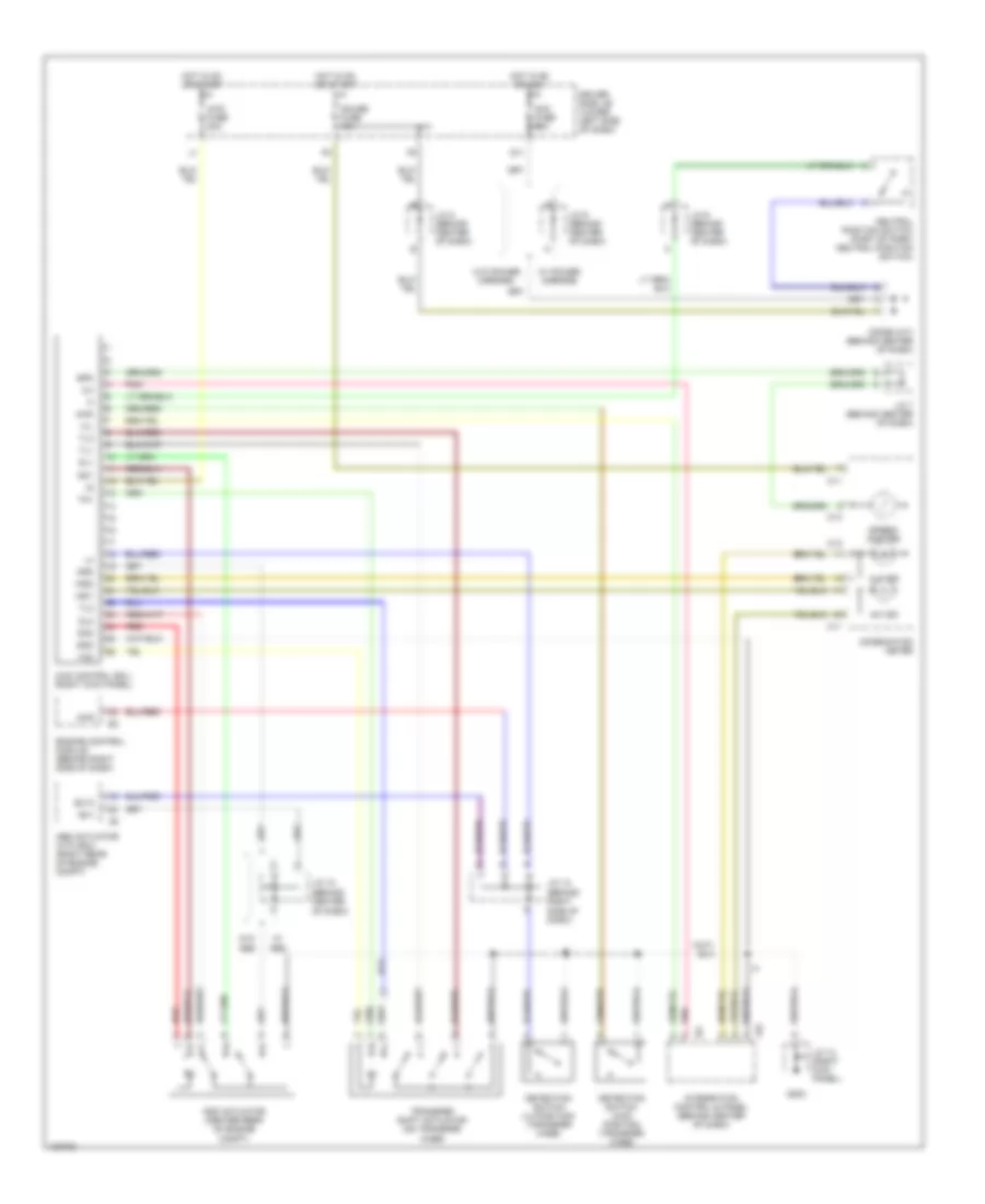
4.7L, 4WD Wiring Diagram for Toyota Tundra SR5 2000
List of elements for 4.7L, 4WD Wiring Diagram for Toyota Tundra SR5 2000:
- (behind center of dash)
- (behind right side of dash)
- 2-4
- 4hi ind
- 4lo ind
- 4wd
- 4wd control ecu (right kick panel)
- 4wd fuse 20a
- Abs actuator with ecu (right rear of engine compt)
- Acc fuse 15a
- Add
- Add actuator (center rear of engine compt)
- C11
- C12
- C13
- Combination meter
- Detection switch (4wd positon) (transfer case)
- Detection switch (l4 position) (transfer case)
- Didoe (a/t) (behind center of dash)
- Dl1
- Dl2
- Dm1
- Dm2
- Driver side j/b (lower left side of dash)
- Engine control module (behind right side of dash)
- Ex1
- Ex13
- G11
- G203
- Gauge fuse 10a
- Gnd
- H-l
- Hot in on or acc
- Hot in on or start
- I24
- Ind1
- Ind2
- Integration control & panel (behind center of dash)
- J/c 10
- J/c 12
- J/c 13 (right kick panel)
- J/c 6 (behind center of dash)
- J/c 7 (behind center of dash)
- J/c 8 (behind center of dash)
- J/c 9 (behind center of dash)
- Neutral position switch (part of park/ neutral position switch)
- Pnk
- Red
- Spd
- Speed- ometer
- Tl1
- Tl2
- Tl3
- Tm1
- Tm2
- Transfer shift actuator (on transfer case)
- W/ abs
- W/ power mirrors
- W/o abs
- W/o power mirrors
4.7L, A/T Wiring Diagram for Toyota Tundra SR5 2000
List of elements for 4.7L, A/T Wiring Diagram for Toyota Tundra SR5 2000:
- (left side of eng compt, next to battery) j/c j1
- 2 ind
- A/t indicator switch (park/neutral position switch) (on transmission)
- A/t oil temperature sensor (on transmission)
- Acc fuse 15a
- B+1
- Batt (b+)
- D ind
- Data link connector 1 (on left side of eng)
- Diode (upper right of instrument cluster)
- Driver side j/b (lower left side of dash)
- E01
- Efi 1 fuse 15a
- Efi relay (eng room r/b)
- Electronically controlled transmission solenoids
- Engine control module (behind right side of dash, near "a" pillar)
- Engine controls
- Engine coolant temperature sensor (on right front of eng)
- Engine room r/b (left side of eng compt)
- Eo2
- Eo3
- F11
- G100 (center of left front fender)
- G11
- G116 (left side of fire- wall)
- G117 (right rear of eng)
- G200
- Gauge fuse 10a
- Hot at all times
- Hot in acc or on
- Hot in on or start
- I10
- I5 (dash harn, upper right side of dash)
- I7 (dash harn, near right grommet)
- Ign fuse 5a
- Igsw
- J/c 3 (left kick panel)
- J/c j11 (behind upper right side of dash, near air bag)
- J/c j12 (behind upper right side of dash)
- J/c j8 (behind upper left side of dash)
- J/c j9 (behind upper left side of dash)
- L ind
- Meo1
- Mrel
- N ind
- Nco+
- Nco-
- No. 1
- No. 2
- No. 3
- O/d direct clutch speed sensor (on left side of transmission)
- O/d main switch
- Od off
- Od2
- Oil
- Oil temp
- Oil-w
- P ind
- R ind
- Red
- Slt
- Slt+
- Slt-
- Sp2+
- Sp2-
- Spd
- Speedo
- Stop fuse 15a
- Stoplamp switch (on bracket, above brake pedal)
- Te1
- Throttle position sensor (on throttle body assembly)
- Thw
- Vcc
- Vehicle speed sensor (for ect) (on transmission)
- Vta
- Vta2