TRANSMISSION
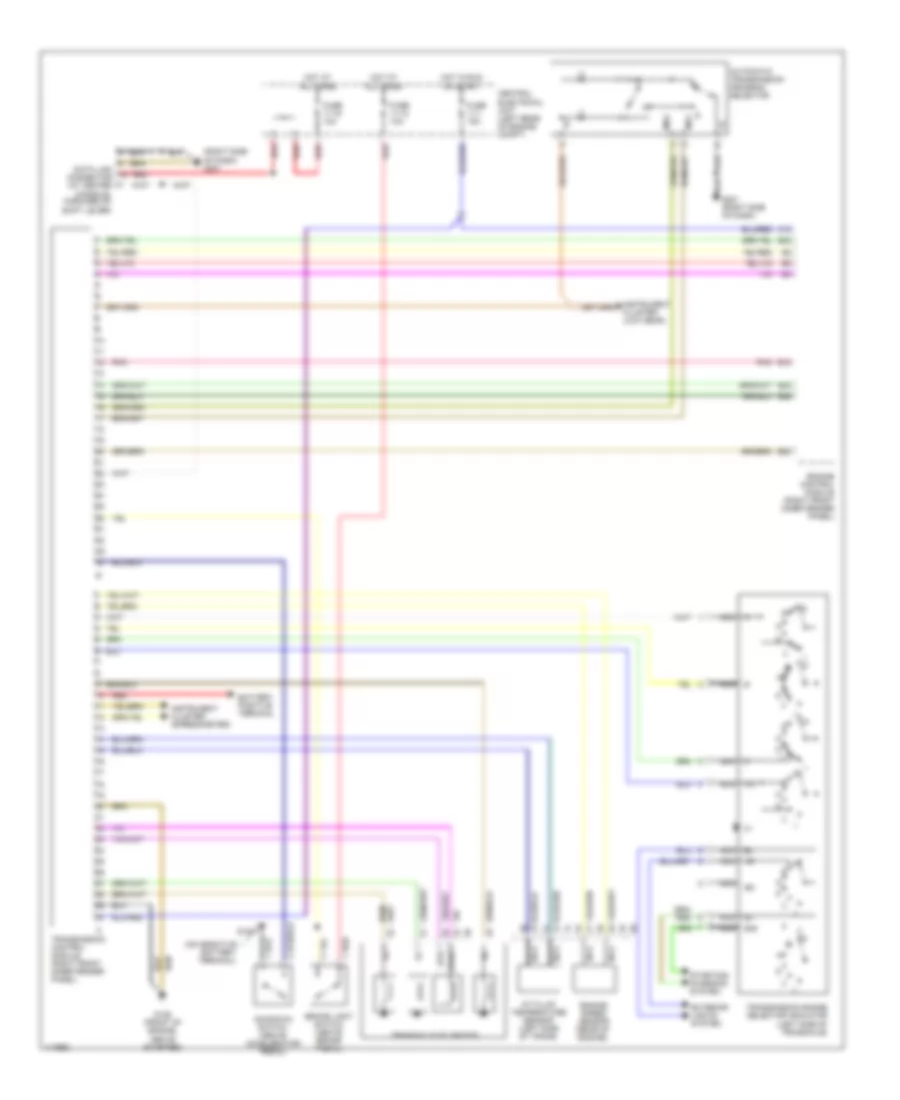
A/T Wiring Diagram for Volvo 850 GLT 1997
List of elements for A/T Wiring Diagram for Volvo 850 GLT 1997:
- (right side of dash) g201
- 15i
- 50s
- A/t fluid temperature sensor (left side of trans)
- A12
- Automatic transmission program selector
- B12
- B20
- B24
- B26
- B42
- Battery positive terminal
- Brake light switch (above brake pedal)
- Central electrical unit (left rear of engine compt)
- Data link connector (at center console, forward of shift lever)
- Engine control module (right front inner fender panel)
- Engine speed sensor (rear of engine)
- Exterior lights system
- Fuse 11-1 15a
- Fuse 11-12 10a
- Fuse 11-15 10a
- G100
- G125 (front of engine, above starter)
- G201 (right side of dash)
- Hot at all times
- Hot in run or start
- Instrument cluster (low gear)
- Instrument cluster (speedometer)
- Kickdown switch (above accelerator pedal)
- Ms1
- Ms2
- Nca
- Pnk
- Red
- Starting/ charging system
- Sth
- Sthg
- Transaxle solenoids
- Transmission control module (right front inner fender panel)
- Transmission range selector indicator (left side of transaxle)
 English