TRANSMISSION
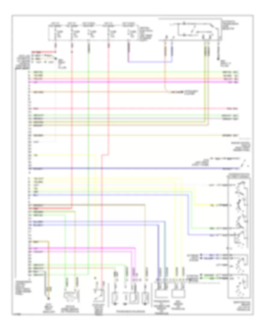
A/T Wiring Diagram for Volvo V70 R 1998
List of elements for A/T Wiring Diagram for Volvo V70 R 1998:
- (at center console, forward of shift lever)
- 15i
- 50s
- Automatic transmission mode selector
- B12
- B20
- B24
- B26
- B42
- Central electrical unit (left rear of engine compt)
- Data link connector
- Engine control module (right front fender panel)
- Exterior lights system
- Fuse b1 10a
- Fuse b4 10a
- Fuse c11 10a
- Fuse c2 10a
- Fuse c5 15a
- G102 (left front strut tower)
- G107 (below right headlamp)
- G901 (right "a" pillar)
- Gear position sensor (on top of transaxle)
- Hot at all times
- Hot in run or start
- Ind
- Instrument cluster
- Kickdown switch (on throttle body)
- Ms1
- Ms2
- Nca
- Pnk
- Red
- Rpm sensor (on transaxle)
- Starting/ charging system
- Sth
- Sthg
- Stoplight switch (above brake pedal)
- Transmission control module (right front inner fender panel)
- Transmission oil temperature sensor (on transaxle)
- Transmission solenoids
- Vehicle speed sensor (on transaxle)
 English