TRANSMISSION
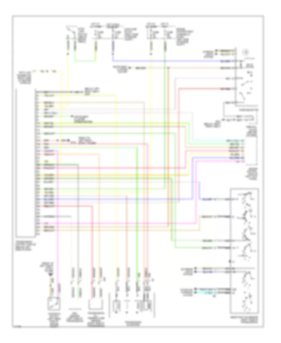
A/T Wiring Diagram for Volvo V90 1998
List of elements for A/T Wiring Diagram for Volvo V90 1998:
- (below left front seat) g300
- (front of left front strut tower)
- (front of left front strut tower) g102
- 15i nca
- 50s nca
- A nca
- A35
- B nca
- Bl nca
- C nca
- Data link connector (right side of center console)
- Engine compartment fuse/relay block (left side of engine compt)
- Engine control module (left kick panel)
- Exterior lights system
- Fuse b1 5a
- Fuse b6 15a
- Fuse c11 5a
- Fuse c3 15a
- G102
- G301 (below right front seat)
- Gear position sensor (right side of transmission)
- Hot at all times
- Hot in run
- Hot in run or start
- Instrument cluster (o/d off)
- Instrument cluster (speedometer)
- Interior lights system
- Kickdown switch (left rear side of engine compt)
- Main fuse block (right side of engine compt)
- Mode selector
- Nca
- Pa nca
- Pnk
- Rpm sensor (left side of transmission)
- Solid state
- Starting/ charging system
- Sth
- Sthg
- Stop lamp switch (above brake pedal)
- Terminal block (center of dash)
- Transmission control module (behind left side of dash)
- Transmission oil temperature sensor (right side of transmission)
- Transmission solenoids
 English