TRANSMISSION
Transmission Wiring Diagram for Volvo XC70 T-6 2011
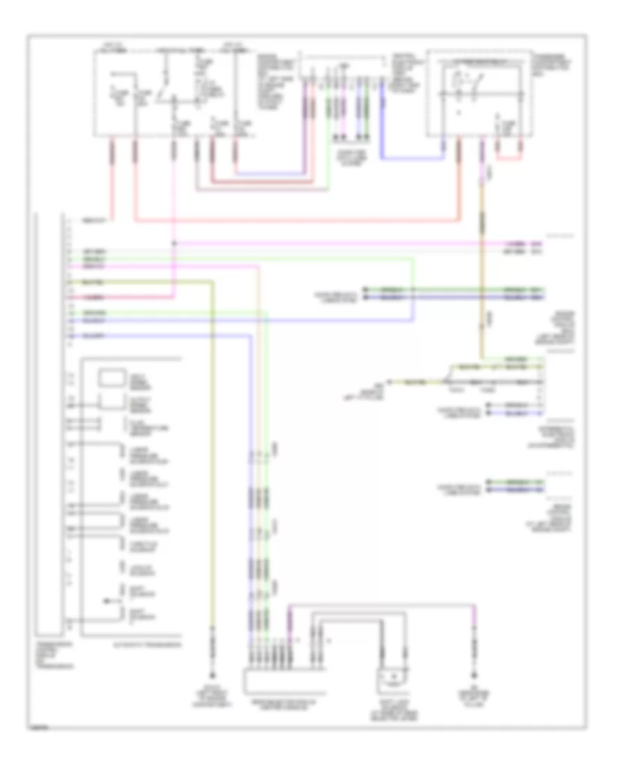
List of elements for Transmission Wiring Diagram for Volvo XC70 T-6 2011:
- 15- feed relay
- 15-feed rear relay
- 74/301
- 74/403
- 74/411
- 74/511
- 74/514
- 74/520
- Automatic transmission
- B13
- B15
- B41
- B54
- Brake control module (at left rear of engine compt)
- Cem
- Central electronic module (cem) (behind right end c2
- Computer data lines system
- Differential electronic module (on differential)
- Engine compartment distribution box (at left side of engine compt, forward of strut tower)
- Engine control module (ecm) (left rear of engine compt)
- Fluid temperature sensor
- Fuse a1 50a
- Fuse a2 50a
- Fuse a5 60a
- Fuse b20 10a
- Fuse b27 5a
- Fuse b31 15a
- Fuse c29 10a
- G6 (near base of left "b" pillar)
- G65 (base of left "c" pillar)
- Gear selector module (center console)
- Gxx10 (left front of engine compartment)
- Hot at all times
- Input speed sensor
- Linear pressure solenoid slb1
- Linear pressure solenoid slc1
- Linear pressure solenoid slc2
- Linear pressure solenoid slc3
- Lock-up solenoid
- Nca
- Of dash)
- Output speed sensor
- Passenger compartment distribution box
- Red
- Shift lock solenoid (at base of gear selector lever)
- Shift solenoid
- Throttle solenoid
- Transmission control module (on transmission)
 English