TRUNK, TAILGATE, FUEL DOOR
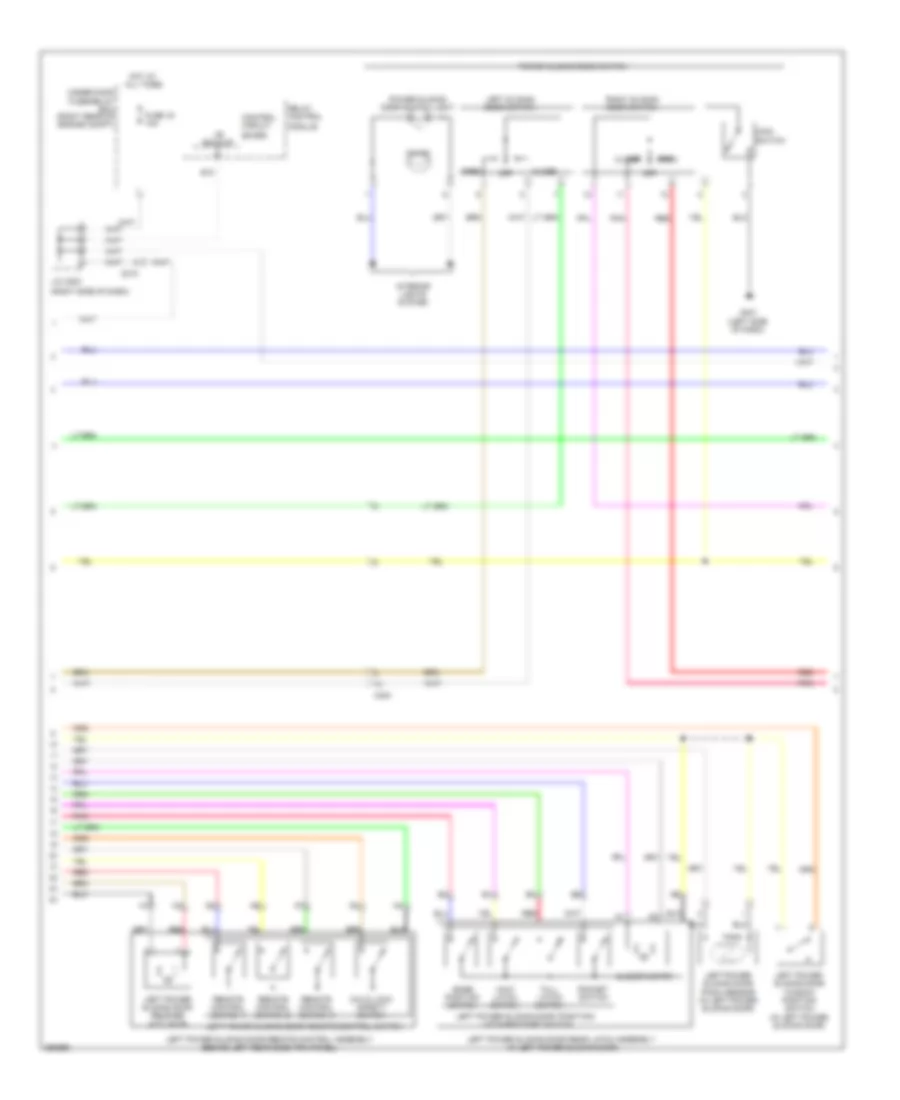
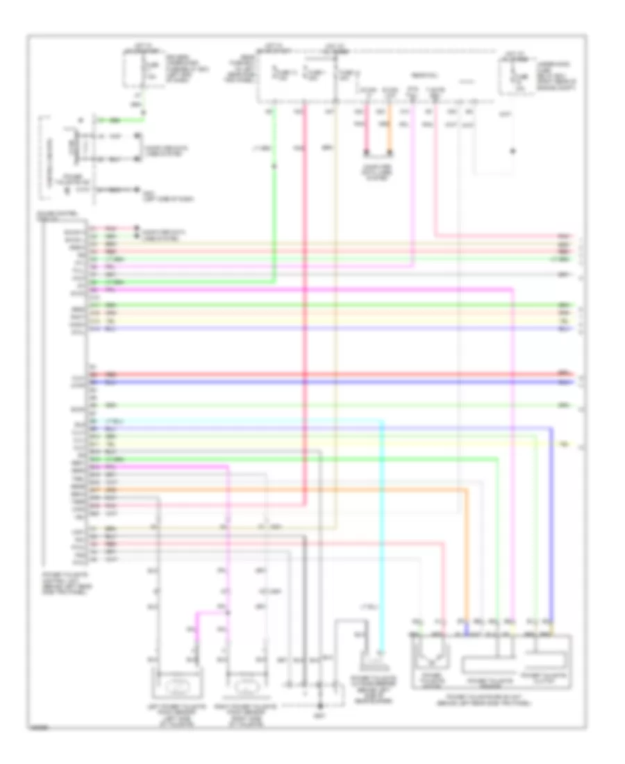
Power Sliding Door Wiring Diagram (1 of 4) for Honda Odyssey Touring 2013

List of elements for Power Sliding Door Wiring Diagram (1 of 4) for Honda Odyssey Touring 2013:
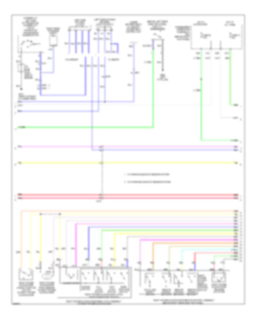
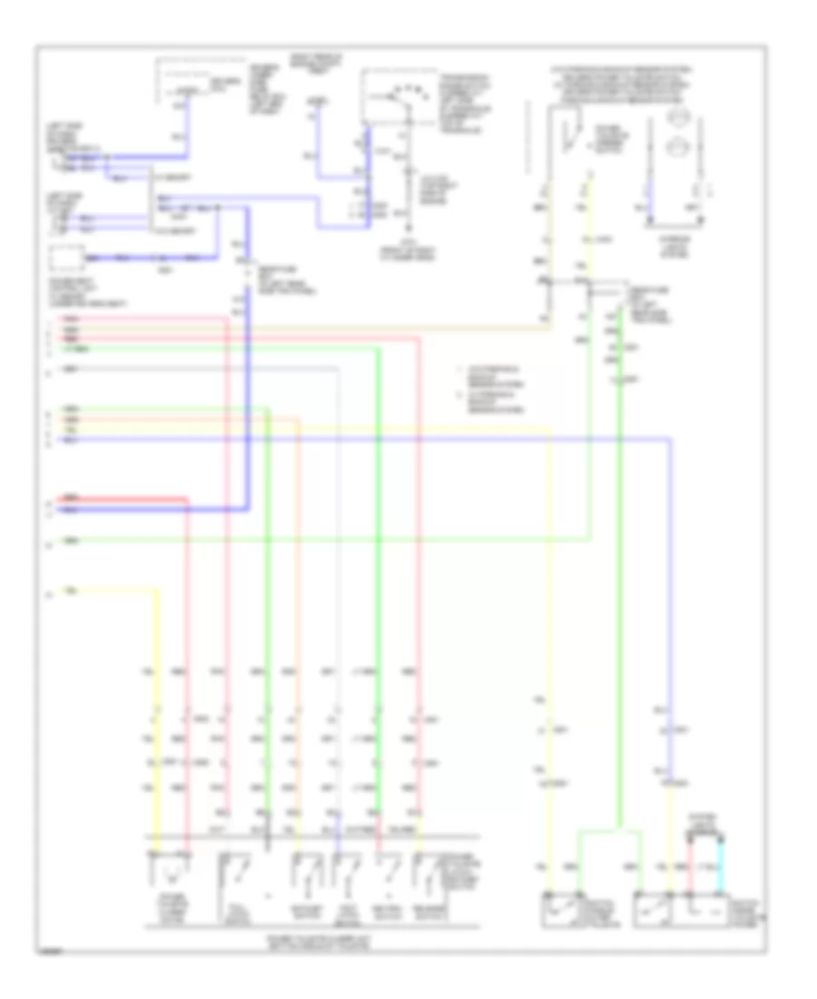
Power Sliding Door Wiring Diagram (2 of 4) for Honda Odyssey Touring 2013
List of elements for Power Sliding Door Wiring Diagram (2 of 4) for Honda Odyssey Touring 2013:
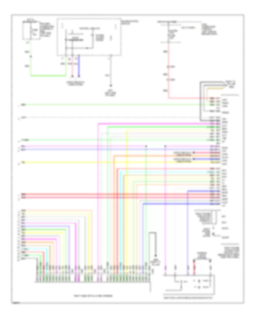
Power Sliding Door Wiring Diagram (3 of 4) for Honda Odyssey Touring 2013
List of elements for Power Sliding Door Wiring Diagram (3 of 4) for Honda Odyssey Touring 2013:
Power Sliding Door Wiring Diagram (4 of 4) for Honda Odyssey Touring 2013
List of elements for Power Sliding Door Wiring Diagram (4 of 4) for Honda Odyssey Touring 2013:
Power Tailgate Wiring Diagram (1 of 2) for Honda Odyssey Touring 2013
List of elements for Power Tailgate Wiring Diagram (1 of 2) for Honda Odyssey Touring 2013:
Power Tailgate Wiring Diagram (2 of 2) for Honda Odyssey Touring 2013
List of elements for Power Tailgate Wiring Diagram (2 of 2) for Honda Odyssey Touring 2013:
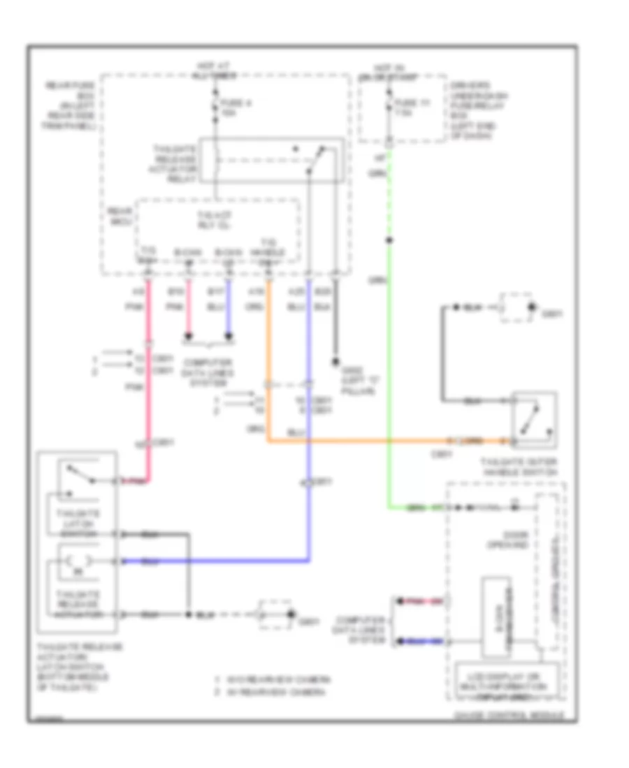
Tailgate Release Wiring Diagram for Honda Odyssey Touring 2013
List of elements for Tailgate Release Wiring Diagram for Honda Odyssey Touring 2013: