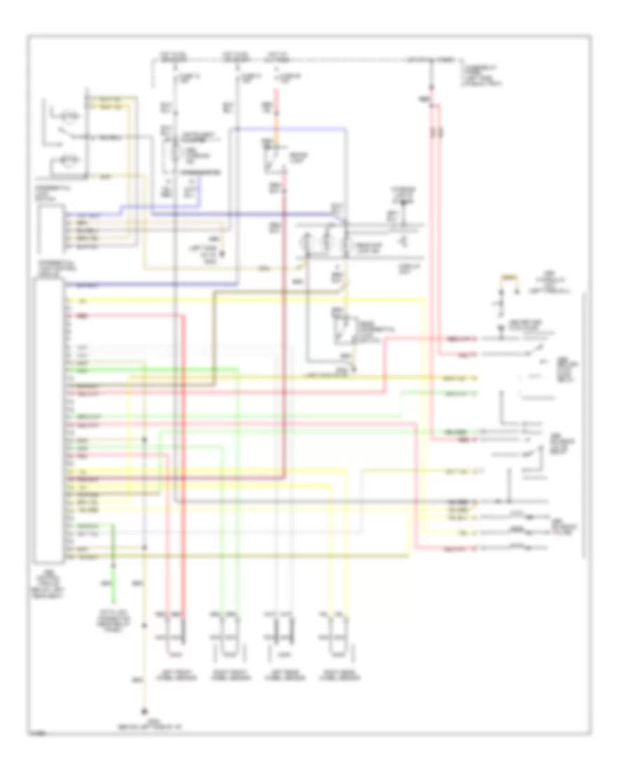
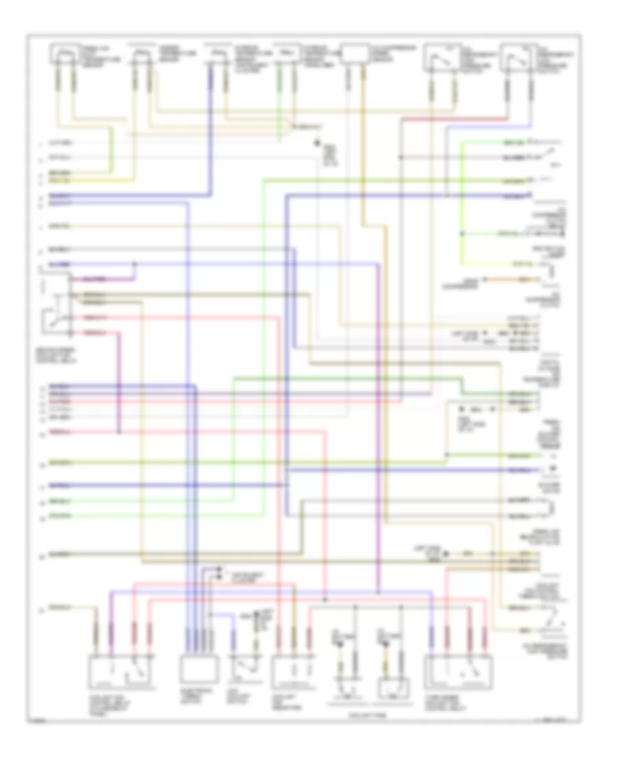
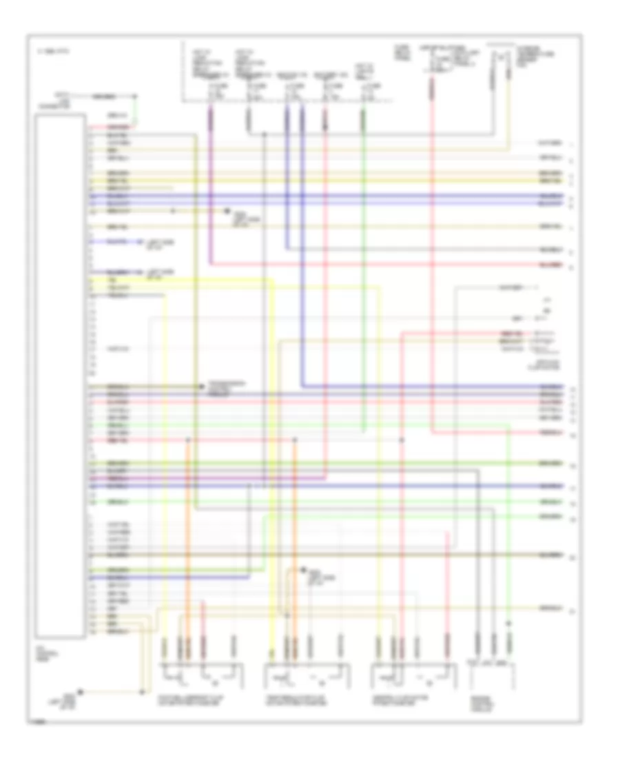
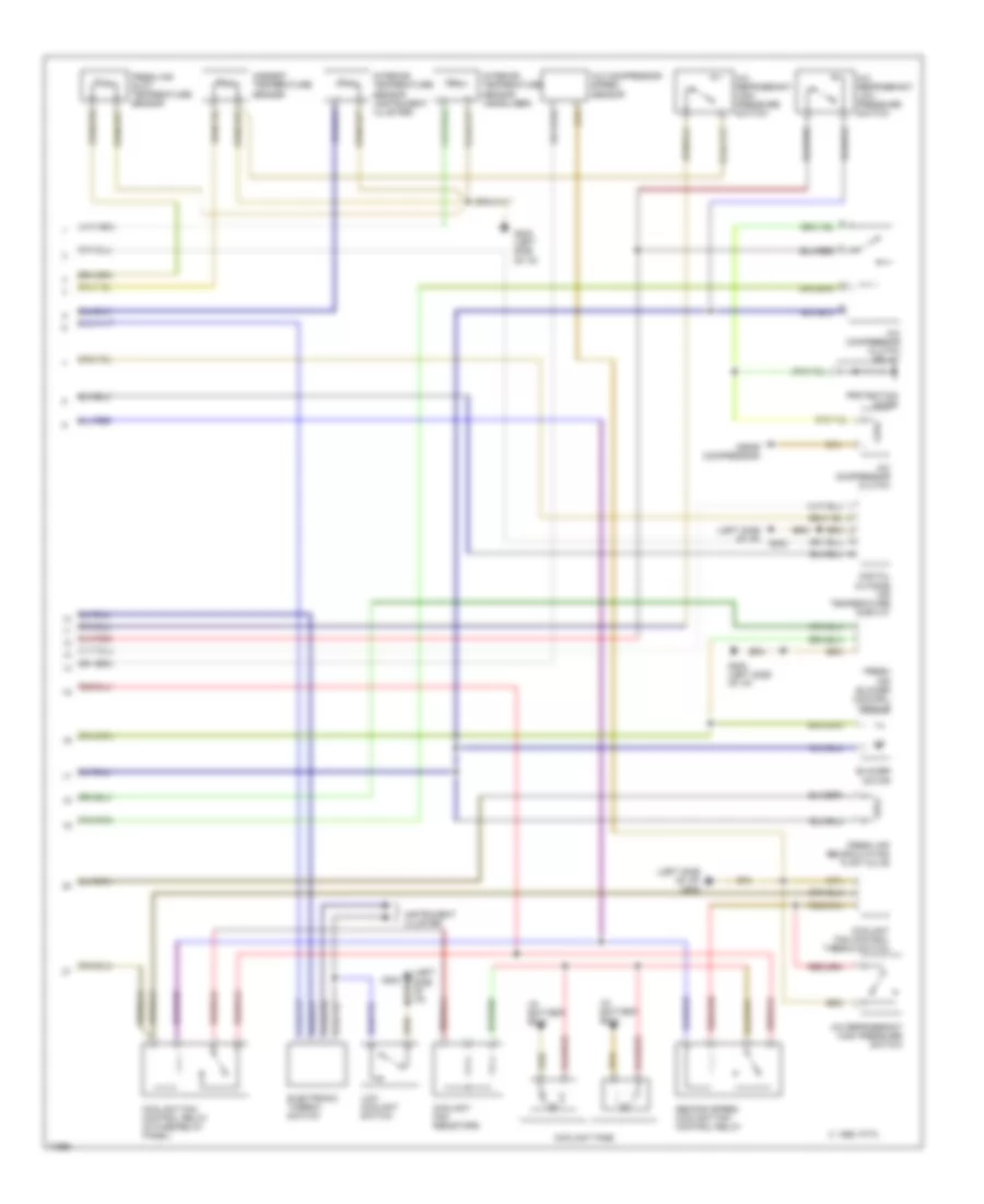
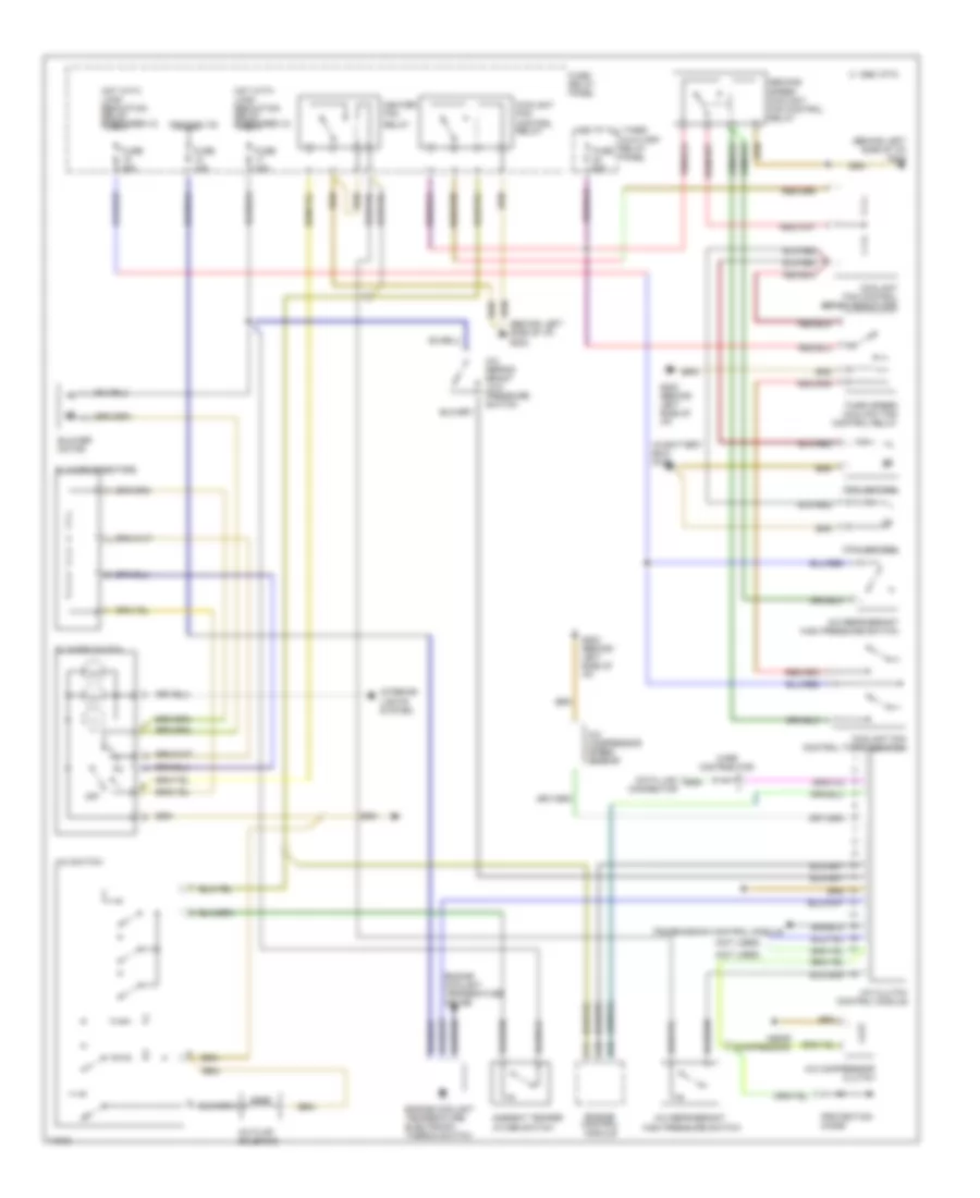
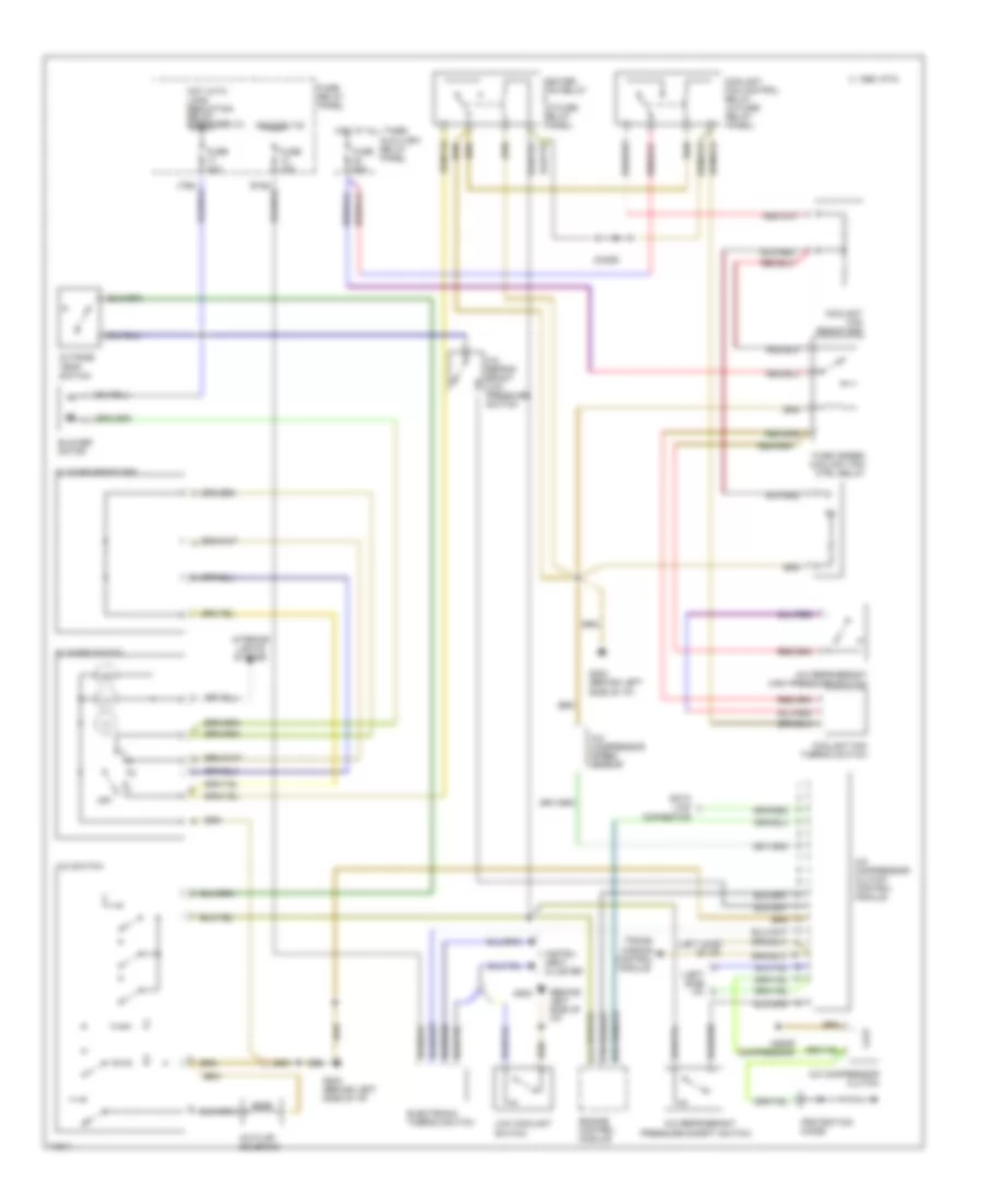
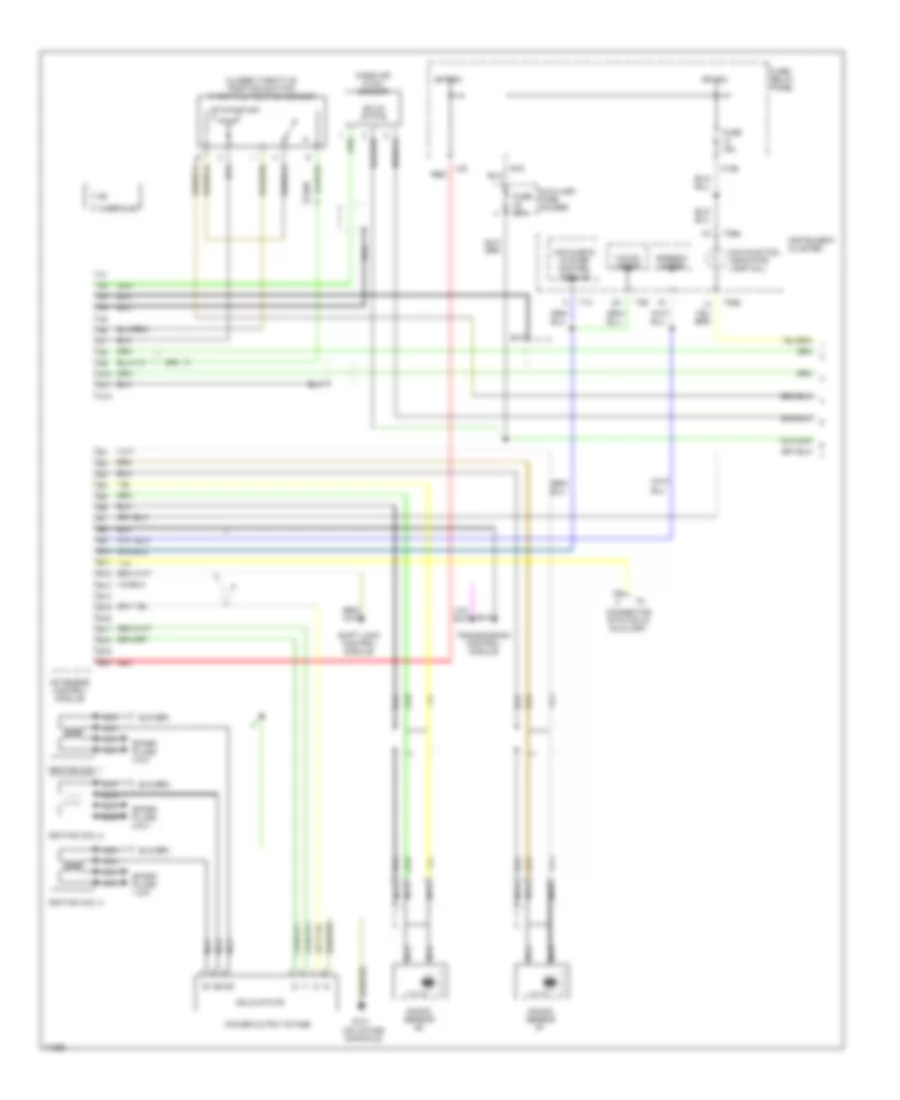
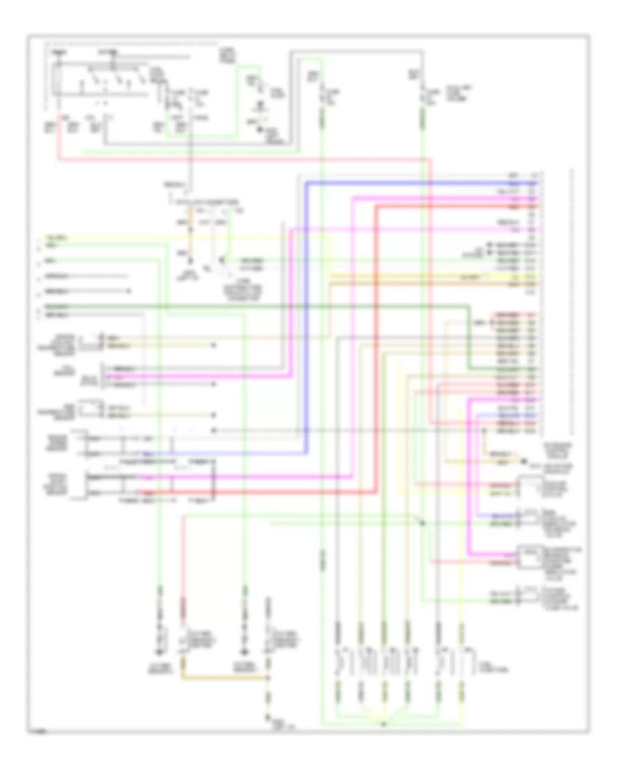
Автомтическая коробка Передач (АКПП) Полная привод (4WD) Блокировка Дифференциала
Электросхема автоматической коробки передач АКПП для Audi 90 1995
 https://portal-diagnostov.com/license.html
Automotive Electricians Portal FZCO
Automotive Electricians Portal FZCO
https://portal-diagnostov.com/license.html
https://portal-diagnostov.com/license.html
Automotive Electricians Portal FZCO
Automotive Electricians Portal FZCO
Электросхема автоматической коробки передач АКПП для Audi 90 1995 - Список элементов:
- (left side of i/p)
- 2-5
- 25-28
- 30-39
- 48-53
- 50a
- 50z
- 52-53
- 7-8
- 87a
- A/c kickdn
- Air conditioning system
- Atf temp
- Automatic transmission console light
- Auxiliary relay panel (left i/p)
- B10
- B11
- B12
- B13
- Bat
- Brake light switch (on pedal cluster)
- Brake lt sw
- C10
- C15a
- Central locking/ alarm system/ interior light delay control module (behind right side of rear seat)
- Cruise control system
- Data link connector (in plenum tray)
- E50a
- Ecm
- Engine control module (right side of dash, behind glove box)
- Exterior lights system
- F30al
- F50z
- Fuse 10a
- Fuse 15a
- Fuse 5a
- Fuse/ relay panel (left side plenum tray)
- G131 (on intake manifold)
- G202 (left side of i/p)
- Generator terminal d+
- Ground
- Hot at all times
- Hot in on or start
- Ign time adj
- Ignition switch terminal 50 (hot in start)
- Interior lights system
- K wire diag
- Kick-down switch (on throttle housing)
- Kickdn sw
- L30
- M-f switch
- Multi-function transmission range switch (rear of gear box housing)
- On/start v
- Only
- P/n
- Park/ neutral position relay
- Pk/neut sig
- Protection diode
- R n
- Red
- Red/ starter terminal
- Rpm sig
- Selector lever light relay
- Shift interlock system
- Sol supp v
- Solenoid 1
- Solenoid 2
- Solenoid 3
- Solenoid 4
- Solenoid 5
- Solenoid 6
- Solenoid 7
- Solenoid valves
- Spd ctrl sw
- Tps signal v
- Tr display
- Transmission control module (behind left side of dash)
- Transmission fluid temperature sensor
- Transmission range selector lever display
- Transmission vehicle speed sensor
- Valve body
- Vehicle speed sensor (rear left side of engine)
- Vss
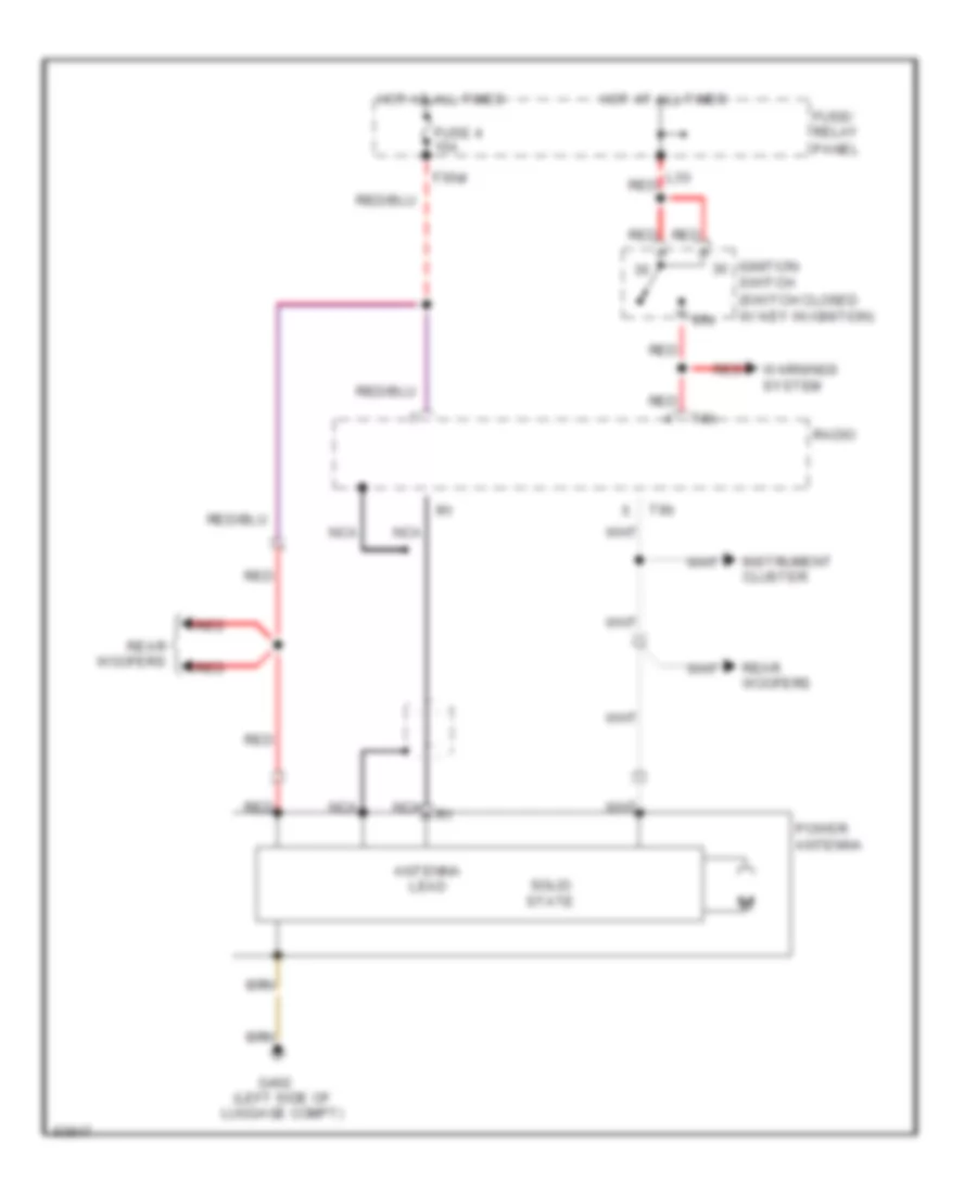
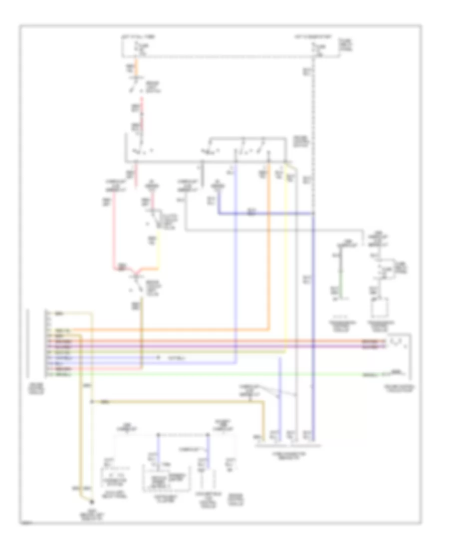
АНТЕННА ПИТАНИЯ
Электросхема антенны для Audi 90 1995
Электросхема антенны для Audi 90 1995 - Список элементов:
- (switch closed w/ key in ignition)
- 86s
- Antenna lead
- F30al
- Fuse 4 15a
- Fuse/ relay panel
- G402 (left side of luggage compt)
- Hot at all times
- Ignition switch
- Instrument cluster
- L30
- Nca
- Power antenna
- Radio
- Rear woofers
- Red
- Solid state
- T8b
- Warnings system
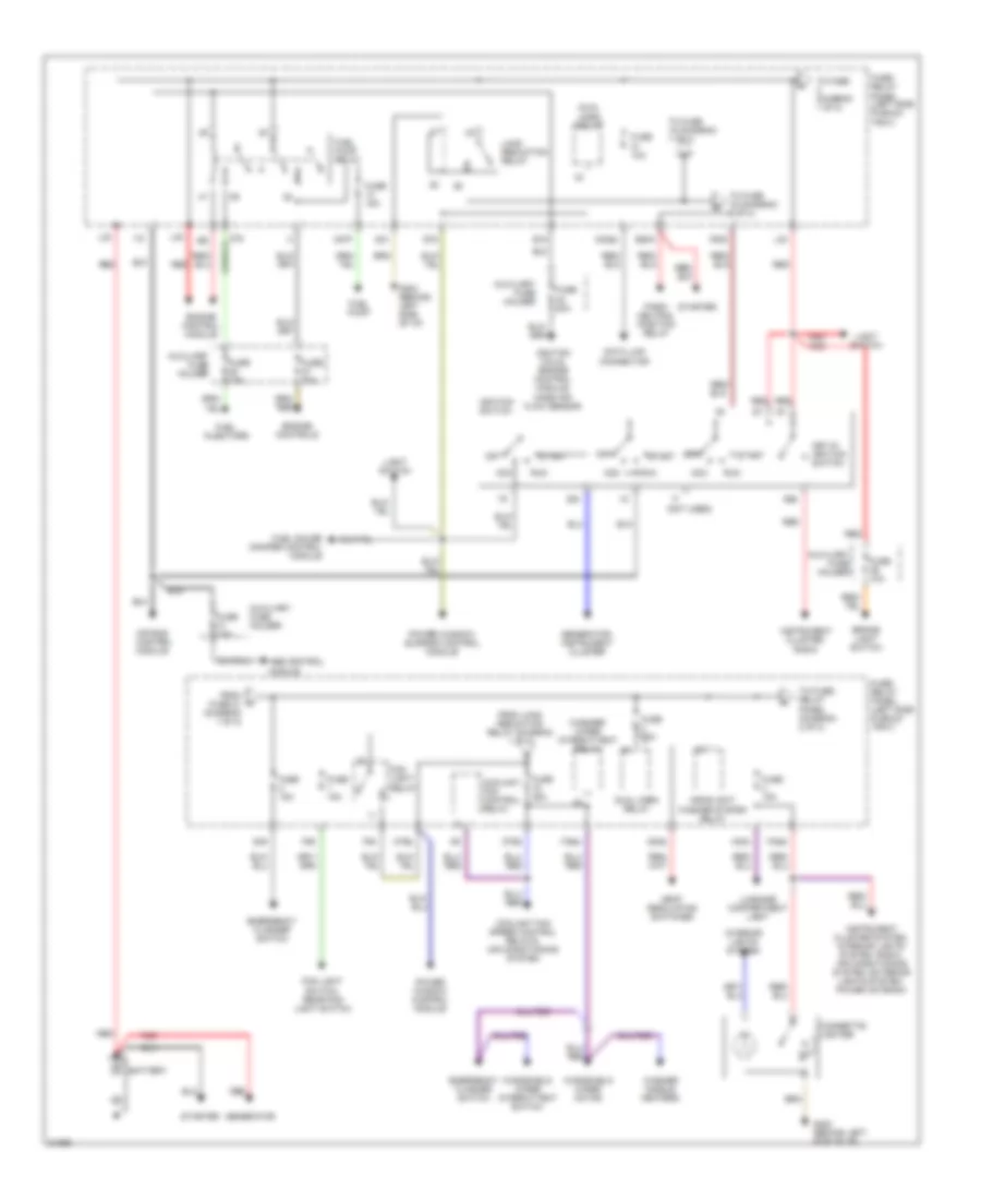
БЛОК ПРЕДОХРАНИТЕЛЕЙ И РЕЛЕ
Электросхема блока предохранителей и реле (1 из 2) для Audi 90 1995
Электросхема блока предохранителей и реле (1 из 2) для Audi 90 1995 - Список элементов:
- (not used)
- 50b
- 75n
- 86s
- 87a
- Abs control module
- Acc
- Air bag control module
- Auxiliary fuse holder
- B15
- Battery
- Brake light switch
- Cigarette lighter
- Coolant fan control relay
- Coolant fan speed control relays, air conditioning system
- D75a
- Data link connector
- Dual horn relay
- E50a
- Emergency flasher switch
- Engine control module
- Engine controls
- F30al
- F50z
- F55
- Fog light relay
- Fog light switch, rear fog light switch
- From fuse 21 (diagram 1 of 2)
- From load reduction relay (diagram 1 of 2)
- Fuel gauge damper control module
- Fuel injectors
- Fuel pump
- Fuel pump relay
- Fuse 10a
- Fuse 15a
- Fuse 20a
- Fuse 25a
- Fuse/ relay panel (left side plenum tray)
- G202 (behind left side of i/p)
- G30a
- G31
- G49
- G75
- Generator
- Generator, instrument cluster
- H30b
- H87f
- Headlight washer system relay
- I15
- I75aw
- Ignition coils, engine control module, mass air flow sensor
- Ignition switch
- Instrument cluster system, interior lights system, radio, air conditioning system, exterior lights system, power antenna
- Instrument cluster, radio
- Interior lights system
- Key-in ignition switch
- L30
- Light switch
- Load reduction relay
- Luggage compartment light
- M30ac
- M75s
- Off
- Park/ neutral position relay
- Power window control module
- Power window/ sunroof control module
- Red
- Run
- Seat regulating switches
- Start
- Starter
- To fuse (diagram 1 of 2)
- To fuse 15 (diagram 1 of 2)
- To fuse 16 (diagram 2 of 2)
- To fuse/ relay panel (diagram 2 of 2)
- Washer nozzle heaters
- Washer/ wiper intermittent relay
- Windshield wiper intermittent switch
- Windshield wiper motor
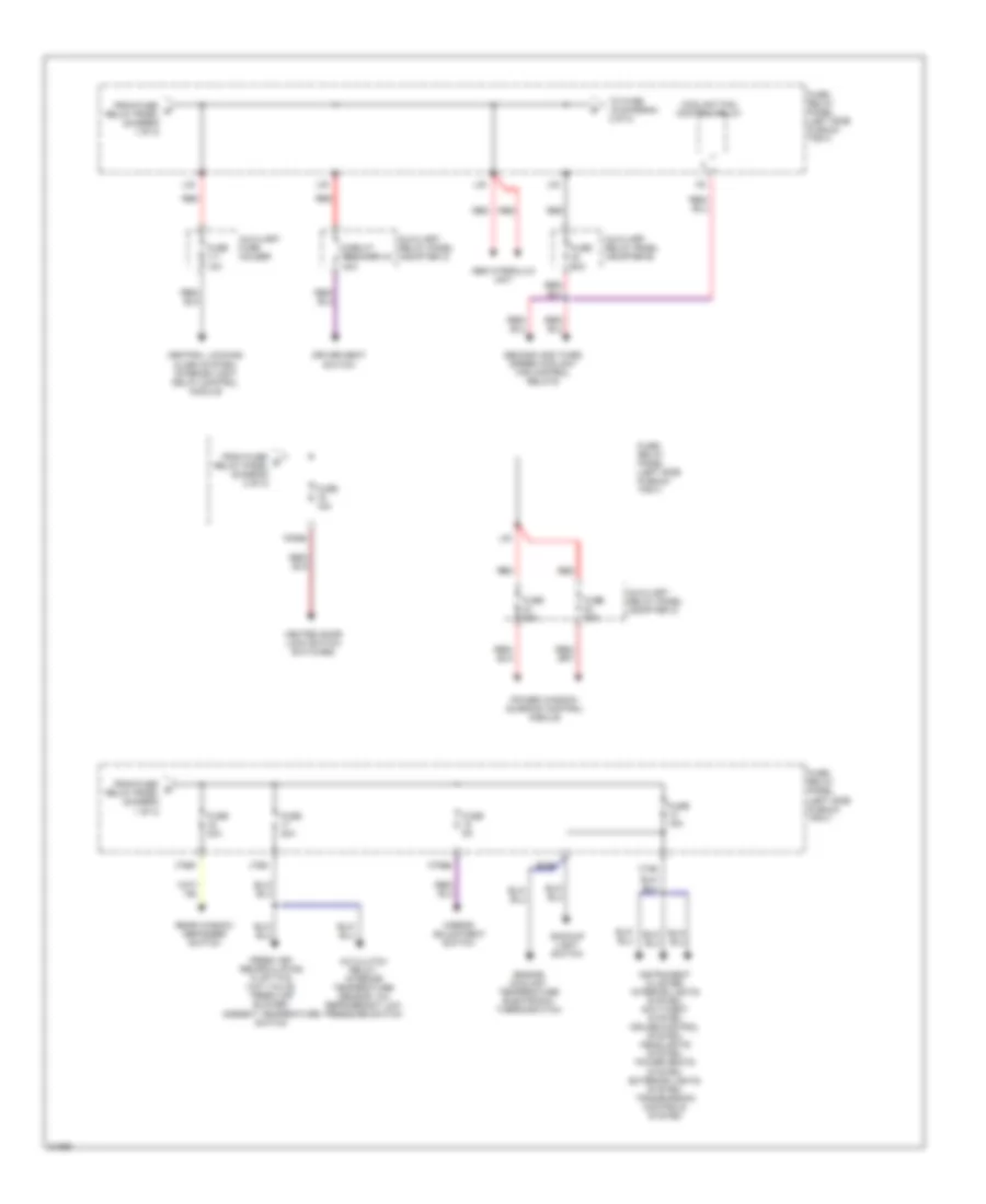
Электросхема блока предохранителей и реле (2 из 2) для Audi 90 1995
Электросхема блока предохранителей и реле (2 из 2) для Audi 90 1995 - Список элементов:
- A/c clutch relay, interior temperature sensor, a/c refrigerant low pressure switch
- Abs hydraulic unit
- Auxiliary fuse holder
- Auxiliary relay panel (adapter b)
- Auxiliary relay panel (adapter c)
- B15a
- Backup light switch
- C15a
- Central locking/ alarm system/ interior light delay control module
- Circuit breaker 44 30a
- Coolant fan control relay
- Driver seat switch
- Engine coolant temperature electronic thermoswitch
- Fresh air/ recirculating flap two way valve, fresh air blower, ambient temperature switch
- From fuse/ b relay panel (diagram 1 of 2)
- From fuse/ d relay panel (diagram 1 of 2)
- From fuse/ e relay panel (diagram 2 of 2)
- Fuse 12a
- Fuse 15a
- Fuse 20a
- Fuse 30a
- Fuse 50a
- Fuse 5a
- Fuse/ relay panel (left side plenum tray)
- Heated door lock switch switches
- Instrument cluster, interior lights system, anti-theft system cruise control system, headlights system, power seats system, exterior lights system, transmission controls system
- J75ah
- J75al
- L30
- M30az
- M75as
- Mirror adjustment switch
- Power window/ sunroof control module
- Rear window defogger switch
- Red
- Second and third speed coolant fan control relays
- To fuse 19 (diagram 2 0f 2)
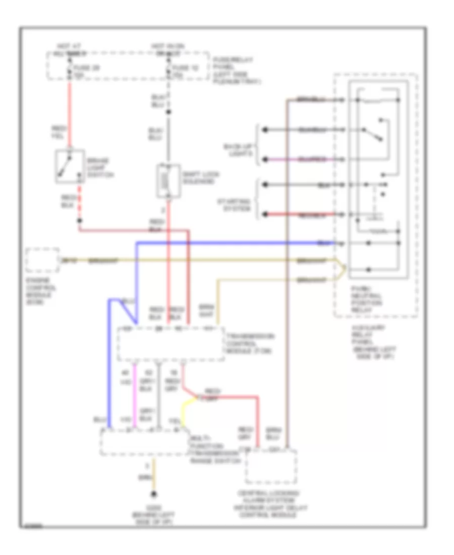
БЛОКИРОВКИ СЕЛЕКТОРА СТОЯНОЧНЫЙ ТОРМОЗ
Электросхема блокировки селектора для Audi 90 1995
Электросхема блокировки селектора для Audi 90 1995 - Список элементов:
- (behind left side of i/p)
- Alarm system/
- Auxiliary relay panel
- B/12
- Back-up lights
- Brake light switch
- C11
- C19
- Central locking/
- Control module
- Engine control module (ecm)
- Function transmission range switch
- Fuse 12 15a
- Fuse 29 10a
- Fuse/relay panel (left side plenum tray)
- G202 (behind left side of i/p)
- Hot at all times
- Hot in on or acc
- Interior light delay
- Multi-
- Park/ neutral position relay
- Shift lock solenoid
- Starting system
- Transmission control module (tcm)
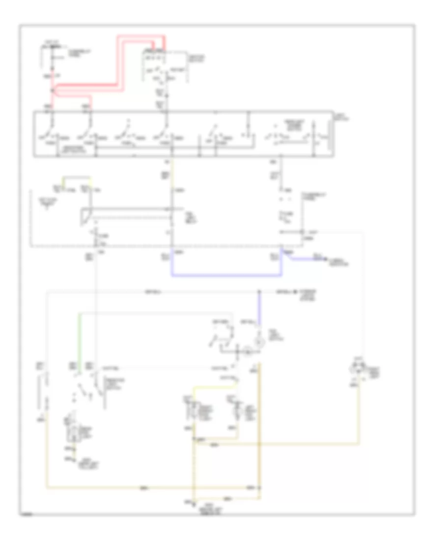
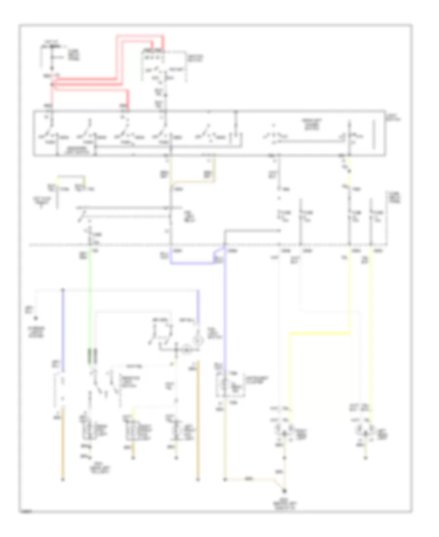
ВНЕШНЕЕ ОСВЕЩЕНИЕ
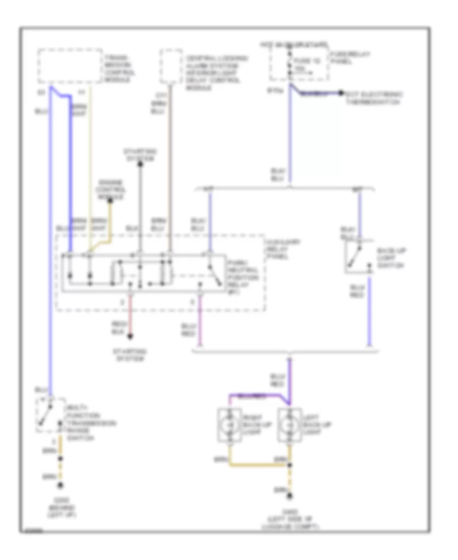
Электросхема заднего хода для Audi 90 1995
Электросхема заднего хода для Audi 90 1995 - Список элементов:
- A/t
- Auxiliary relay panel
- B15a
- Back-up light switch
- C11
- Central locking/ alarm system/ interior light delay control module
- Ect electronic thermoswitch
- Engine control module
- Function transmission range switch
- Fuse 12 15a
- Fuse/relay panel
- G202 (behind left i/p)
- G402 (left side of luggage compt)
- Hot in on or start
- Left back-up light
- M/t
- Multi-
- Park/ neutral position relay (#1)
- Right back-up light
- Starting system
- Trans- mission control module
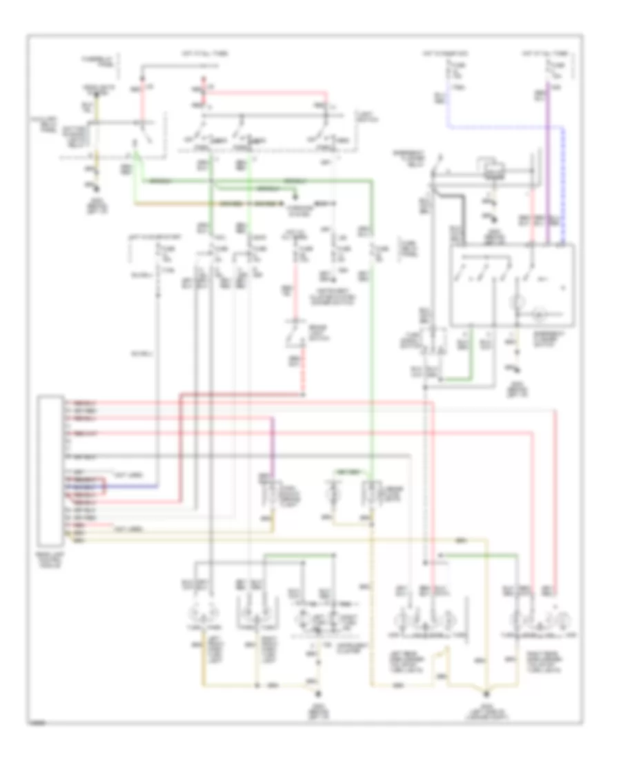
Электросхема внешнего освещения, С DRL для Audi 90 1995
Электросхема внешнего освещения, С DRL для Audi 90 1995 - Список элементов:
- (not used)
- Auxiliary relay panel
- Brake light switch
- C15a
- D 58l
- Daytime running lights relay
- E 58r
- Emergency flasher relay
- Emergency flasher switch
- F57l
- Fuse 10a
- Fuse 15a
- Fuse 5a
- Fuse/ relay panel
- Fuse/relay
- G202 (behind left i/p)
- G402 (left side of luggage compt)
- G49
- G57r
- H 58l
- H 58r
- Head
- Headlights
- High- mount brake light
- Hot at all times
- Hot in on or acc
- Hot in on or start
- I58d
- I75aw
- Instrument cluster
- Instrument cluster system (dimmer switch)
- J30
- J58
- L30
- Left front park/ turn light
- Left rear side marker/ tail/stop/ turn lights
- Left turn ind.
- License plate lights
- Light switch
- Mkr
- Off
- Panel
- Park
- Rear lamp control module
- Red
- Right front park/ turn light
- Right rear side marker/ tail/stop/ turn lights
- Right turn ind.
- Signal switch
- Solid state
- Stop
- System
- T26
- T26a
- Tail
- Turn
- Warnings
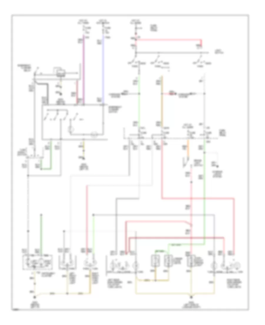
Электросхема внешнего освещения, без DRL для Audi 90 1995
Электросхема внешнего освещения, без DRL для Audi 90 1995 - Список элементов:
- Brake light switch
- D 58l
- E 58r
- Emergency flasher relay
- Emergency flasher switch
- F57l
- Fuse 10a
- Fuse 15a
- Fuse 5a
- Fuse/ relay panel
- G202 (behind left i/p)
- G402 (left side of luggage compt)
- G49
- G57r
- H 58l
- H 58r
- Head
- High- mount brake light
- Hot at all times
- Hot in acc or run
- I58d
- I75aw
- Instrument cluster
- Interior lights system
- J58
- L30
- Left front park/ turn light
- Left rear side marker/ tail/stop/ turn lights
- Left turn ind.
- License plate lights
- Light switch
- Mkr
- Off
- Park
- Red
- Right front park/ turn light
- Right rear side marker/ tail/stop/ turn lights
- Right turn ind.
- Signal switch
- Solid state
- Stop
- System
- T26
- T26a
- Tail
- Turn
- Warnings
ВНУТРЕННЕЕ ОСВЕЩЕНИЕ
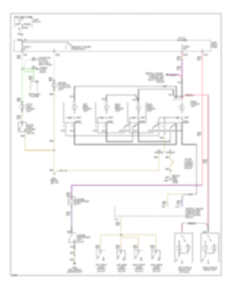
Электросхема ламп подсветки (1 из 2) для Audi 90 1995
Электросхема ламп подсветки (1 из 2) для Audi 90 1995 - Список элементов:
- (behind roof head- liner)
- (optional)
- A/10
- A/12
- A/6
- Alarm system/
- Central locking/
- Central locking/ alarm system/ interior light delay control module
- Cluster
- Connector station (auxiliary relay panel)
- Delay control
- Door
- F30al
- Front interior light
- Fuse 14 5a
- Fuse 4 15a
- Fuse/ relay panel
- G202 (behind left i/p)
- G402 (left side of luggage compt)
- G908
- Glove comp- artment light
- Glove comp- artment light switch
- H30b
- Head
- Headlight washer system relay
- Heater fan switch illumination light
- Hot at all times
- I58d
- Instrument
- Interior light
- J58
- J58a
- Left front door contact switch
- Left make-up mirror light
- Left rear door contact switch
- Left rear reading light
- License plate lights
- Light switch
- Luggage compartment light
- Luggage compartment light switch
- Module
- Nca
- Off
- Park
- Power window/ sunroof control module
- Right front door contact switch
- Right front reading light
- Right make-up mirror light
- Right rear door contact switch
- Right rear reading light
- T26
- W/ sunroof
- W/o sunroof
Электросхема ламп подсветки (2 из 2) для Audi 90 1995
Электросхема ламп подсветки (2 из 2) для Audi 90 1995 - Список элементов:
- C15a
- Driver seat heat regulating switch
- Emergency flasher switch
- Fuse 12 15a
- Fuse 15 25a
- Fuse 18 5a
- Fuse/relay panel
- G202 (behind left i/p)
- Hot in on or acc
- Hot in on or start
- I75aw
- M75as
- Mirror adjustment switch
- Passenger seat heat regulating switch
- Wiper/ washer system
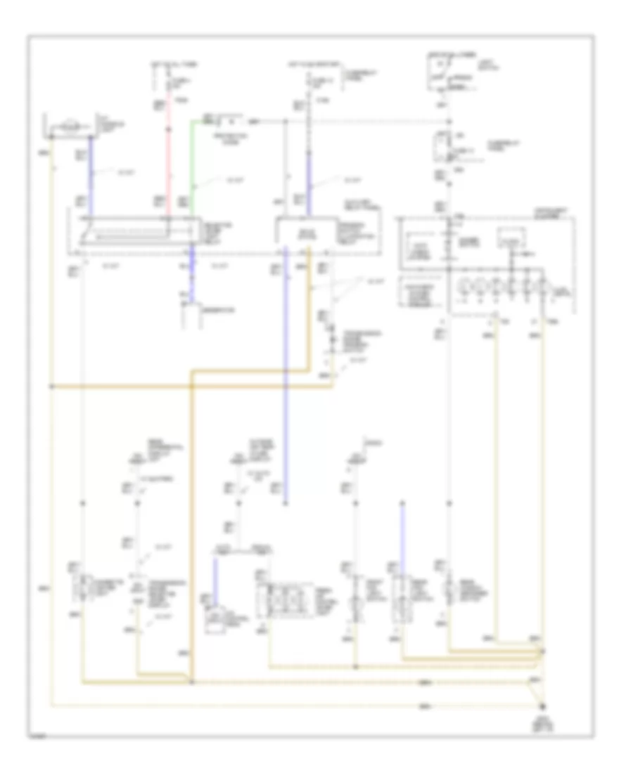
Электросхема подсветки приборов для Audi 90 1995
Электросхема подсветки приборов для Audi 90 1995 - Список элементов:
- A/c control head
- A/t console light
- Auto a/c
- Auto check system
- Auxiliary relay panel
- C15a
- Cigarette lighter light
- Clock
- Dim input
- Dimmer switch
- F30al
- Fresh air control lever light
- Front fog light switch
- Fuse 12 15a
- Fuse 14 5a
- Fuse 4 15a
- Fuse/relay panel
- G202 (behind left i/p)
- Generator
- Gnd
- Head
- Hot at all times
- Hot in on or start
- I58d
- Illum. lights
- Instrument cluster
- J58
- Light switch
- Manual a/c
- Mini-check system control module
- Off
- Outside air temp- ature display
- Park
- Program switch illumination relay
- Protection diode
- Radio
- Rear differential display unit
- Rear fog light switch
- Rear window defogger switch
- Selector lever light relay
- Solid state
- T26
- T26a
- Transmission range program switch
- Transmission range selector lever display
- W/ a/t
- W/ auto a/c
- W/ quatrro
ЗАЗЕМЛЕНИЕ ПОДКЛЮЧЕНИЕ МАССЫ
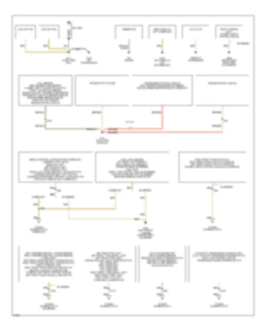
Электросхема подключение массы заземления (1 из 2) для Audi 90 1995
Электросхема подключение массы заземления (1 из 2) для Audi 90 1995 - Список элементов:
- (90 series)
- (cabriolet)
- (near a/c compressor)
- (on engine)
- (w/ a/t)
- A/c clutch
- Abs hydraulic unit (cabriolet)
- Automatic transmission console light, multi-function transmission range switch, shift lock control module, transmission range program switch
- Battery
- Coolant fan
- Datalink connector, vehicle speed sensor, brake fluid level warning switch, heated oxygen sensor 1, heated oxygen sensor 2, kick down switch
- Decklid central locking motor (cabriolet), license plate lights, rear fog light, left backup light, right backup light, trunk lock alarm/ central locking switch, luggage compartment light switch, luggage compartment central locking switch, high mount brake light (cabriolet)
- Engine control module
- Front interior light, power window control module
- Fuel level sensor, left rear lamp assembly, right rear lamp assembly, power antenna (90 series), fuel pump, front lamp control module (90 series), high mount brake light (90 series), rear defogger blower motor
- G111 (in battery box)
- G116 (on hydraulic unit) (95 cabriolet)
- G129 (on transmission)
- G131 (on intake manifold)
- G402 (left side of luggage compartment) (90 series)
- G909 (behind roof headliner) (w/ sunroof)
- Generator
- Ground strap
- Hall sensor, egr temperature sensor, closed throttle position switch, throttle position sensor, engine coolant temperature sensor, crankshaft position sensor shields, engine speed sensor shields, mass air flow sensor, engine control module
- Left front fog light, left front turn signal light, left front park light, engine coolant level warning switch, left headlight, right headlight, high tone horn, low tone horn, right front turn signal light, right front park light, right front fog light, windshield washer pump
- Left infrared central locking sensor, right infrared central locking sensor, alarm horn, left front door central locking switch, right front door central locking switch, front interior light, right front door handle alarm switch, central locking/ alarm system/ interior light delay control module, left front door handle alarm switch
- Power output stage
- Right front window switch, right rear window switch (console), left rear window switch (console), power window control module (w/o sunroof)
- S105
- S119
- S124
- S150
- S83
- S84
- S86
- S89
- S98
- To g202 (diagram 2 of 2)
- To g202 (diagram 2 of 2) (90 series)
- To g202 (diagram 2 of 2) (cabriolet)
- Transmission control module, egr temperature sensor (90 series) vehicle speed sensor shields (cabriolet)
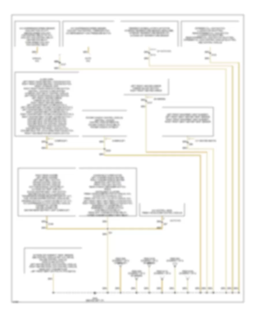
Электросхема подключение массы заземления (2 из 2) для Audi 90 1995
Электросхема подключение массы заземления (2 из 2) для Audi 90 1995 - Список элементов:
- (90 series)
- (auto a/c)
- (cabriolet)
- (manual a/c)
- (w/ auto a/c)
- (w/ heated seats)
- A/c compressor speed sensor, coolant fan (w/ m/t), second speed coolant fan control relay (w/ a/t), coolant fan control relay, heater fan relay, third speed coolant fan control relay
- A/c compressor speed sensor, coolant fan control thermoswitch, a/c refrigerant high pressure switch
- A/c control head, fresh air blower control module
- Alarm horn, left front door central locking switch, right front door central locking switch, front interior light, right front door handle alarm switch, central locking/ alarm system/ interior light delay control module, left front door handle alarm switch, left front heated mirror, mirror adjust switch, right front heated mirror, left compartment cover switch 3, left compartment cover unlocked switch 2, left compartment cover locked switch 1, right compartment cover switch 3, right compartment cover unlocked switch 2, right compartment cover locked switch 1, compartment cover open switch, convertible top position switch, convertible top control module, tensioning bow position switch, convertible top front lock switch, convertible top latch open position switch, front and rear power window switch
- Differential lock switch, illumination (quattro), rear differential lock switch illumination (quattro), rear differential lock switch (quattro), differential lock control module (quattro), abs control module
- From s105 (diagram 1 of 2) (90 series)
- From s119 (diagram 1 of 2)
- From s150 (diagram 1 of 2)
- From s83 (diagram 1 of 2)
- From s86 (diagram 1 of 2) (cabriolet)
- From s89 (diagram 1 of 2) (90 series)
- G202 (behind left i/p)
- Left front backrest heat element, left front seat heater temp. sensor, right front backrest heat element, rihgt front seat heater temp. sensor
- Left front heated mirror, mirror adjust switch, right front heated mirror
- Outside air (ambient) temp. sensor, abs control module (frt whl drive), cruise control module, hood alarm switch, left heated door lock control module, right heated door lock control module, headlight washer pump, left front seat switch (w/ htd seats)
- Power window control module, central locking control module (remote), power window down relay, power window up relay
- Right rear woofer, left rear woofer, left seat belt switch, air bag control module, cruise control module, daytime running lights relay, outside air temp. display, glove compartment light switch, heater fan switch illumination, transmission range selector display (a/t), fuel gauge damper control module (90), program switch illumination relay (w/ a/t), a/c compressor clutch control module, cigarette lighter, cruise connector, center rear ashtray light (cabriolet)
- S100
- S107
- S112
- S127
- S199
- S230
- S236
- S96
- S97
- Temperatur regulator flap motor, interior temperature sensor (headliner), interior temperature sensor (i/p), outside air temperature sensor
- Windshield wiper motor, left washer nozzle heater, right washer nozzle heater, rear fog light switch, front fog light switch, rear window defogger switch, radio, instrument cluster, fresh air blower switch (w/ manual a/c), a/c switch (w/manual a/c), fresh air two way valve (w/ manual a/c), left front seat heat regulating switch, right front seat heat regulating switch, emergency flasher relay, emergency flasher switch, load reduction relay, headlight washer system relay, wiper/ washer intermittent relay
Звуковой сигнал Гудок
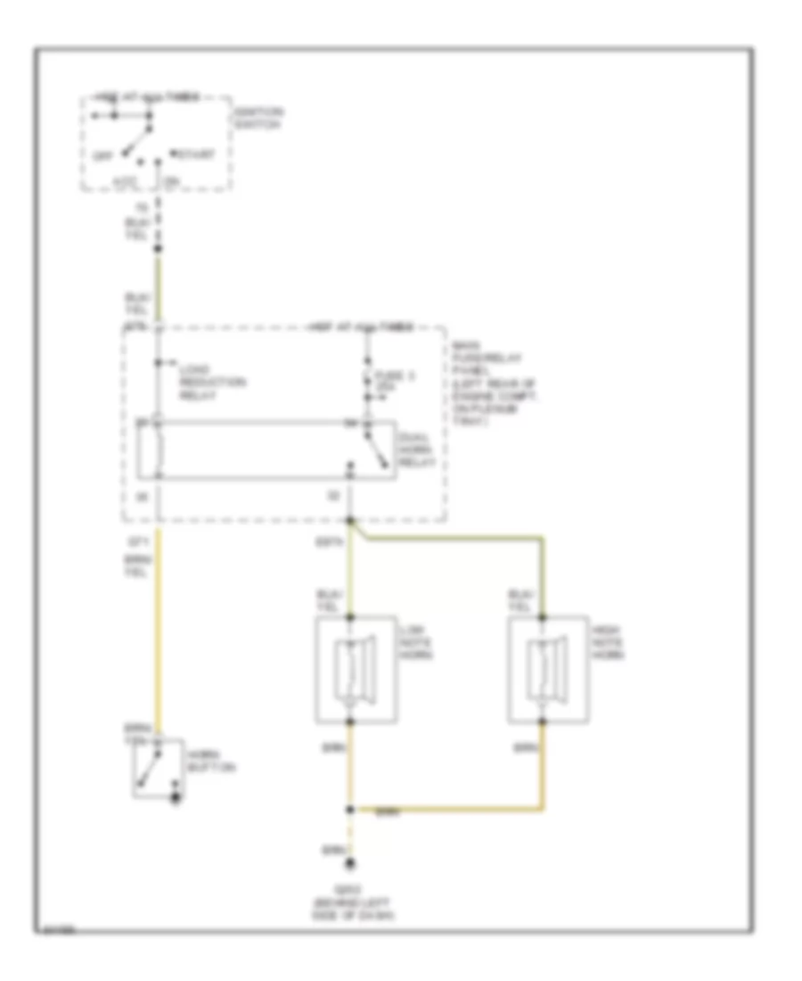
Электросхема звукового сигнал Гудка для Audi 90 1995
Электросхема звукового сигнал Гудка для Audi 90 1995 - Список элементов:
- Acc
- Dual horn relay
- E87h
- Fuse 3 25a
- G202 (behind left side of dash)
- G71
- G75
- High note horn
- Horn button
- Hot at all times
- Ignition switch
- Load reduction relay
- Low note horn
- Main fuse/relay panel (left rear of engine compt, on plenum tray)
- Off
- Start
Магнитола Мультимедия
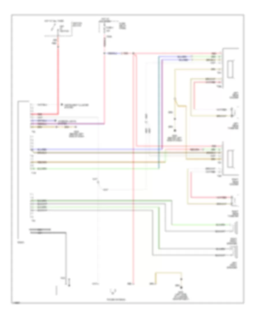
Электросхема магнитолы для Audi 90 1995
Электросхема магнитолы для Audi 90 1995 - Список элементов:
- 15a
- 86s
- F30al
- Fuse 4
- Fuse/ relay panel
- G202 (behind left side of dash)
- G402 (left side of luggage compartment)
- Hot at all times
- Ignition switch
- Instrument cluster system
- Interior lights system
- Key in ignition
- Left front speaker
- Left rear tweeter
- Left rear woofer
- Nca
- Power antenna
- Radio
- Red
- Right front speaker
- Right rear tweeter
- Right rear woofer
- T10h
- T2af
- T2ag
- T5m
- T5n
- T8b
- T8c
Подогрев стекол и зеркал
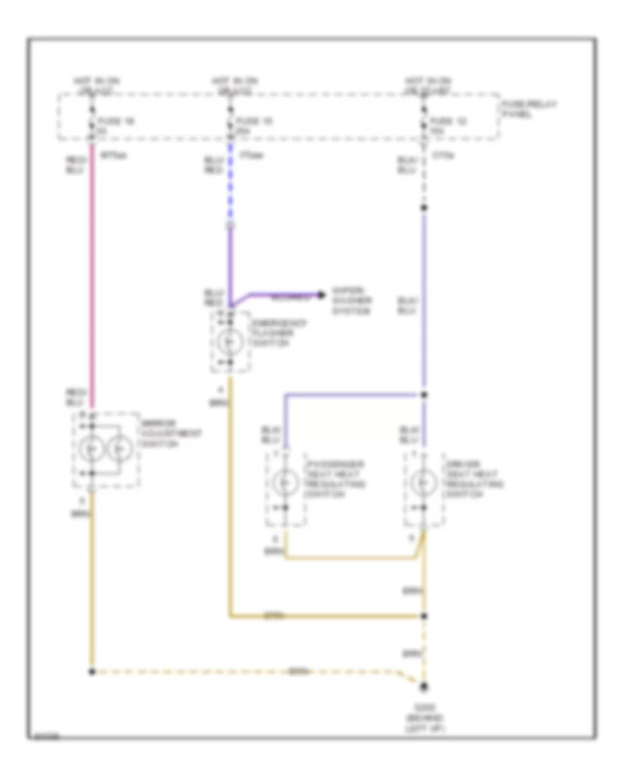
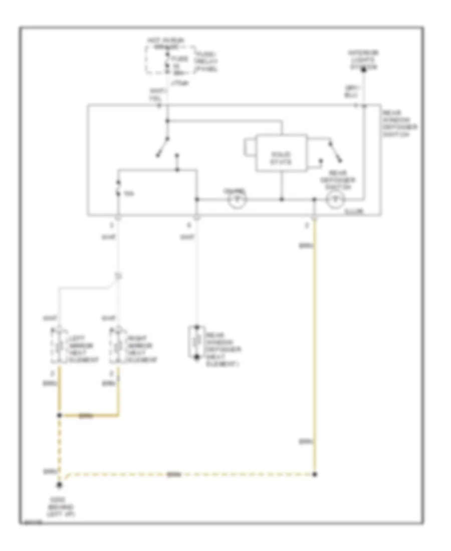
Электросхема подогрева стекол и зеркал для Audi 90 1995
Электросхема подогрева стекол и зеркал для Audi 90 1995 - Список элементов:
- 10a
- Fuse 30a
- Fuse/ relay panel
- G202 (behind left i/p)
- Hot in run
- Illum.
- Interior lights system
- J75ah
- Left mirror heat element
- On ind.
- Or acc
- Rear defogger switch
- Rear window defogger (heat element)
- Rear window defogger switch
- Right mirror heat element
- Solid state
ПОДУШКИ БЕЗОПАСНОСТИ AIR BAG
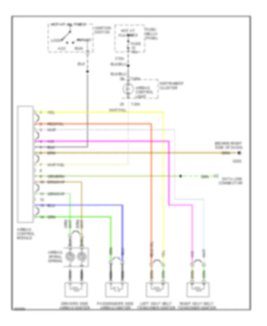
Электросхема подушек безопасности SRS AirBag для Audi 90 1995
Электросхема подушек безопасности SRS AirBag для Audi 90 1995 - Список элементов:
- (behind right side of dash)
- Acc
- Airbag control light
- Airbag control module
- Airbag spiral spring
- C15a
- Data link connector
- Driver's side airbag igniter
- Fuse 15a
- Fuse/ relay panel
- G202
- Hot at all times
- Ignition switch
- Instrument cluster
- Left seat belt tensioner igniter
- Lock
- Nca
- Passenger's side airbag igniter
- Right seat belt tensioner igniter
- Run
- Start
- T26a
ПРЕДУПРЕЖДАЮЩИЕ СИСТЕМЫ
Электросхема предупреждающей системы для Audi 90 1995
Электросхема предупреждающей системы для Audi 90 1995 - Список элементов:
- (0.3 bar)
- (behind left i/p)
- 5/1
- 5/2
- 5/3
- 5/4
- 5/5
- 6/1
- 6/2
- 6/3
- 6/4
- 6/5
- 6/6
- 86s
- A/c system
- Acc
- Auxiliary relay panel
- B10
- B15a
- Back-up lights
- C15a
- Cruise control module, o/s air temp display, a/c control head, shift lock control module, differential lock control module
- Ect electronic thermoswitch
- Engine control module
- Engine coolant level warning switch
- Engine oil pressure switch
- F30al
- Fuel gauge
- Fuel gauge damper control module (#7)
- Fuel level sensor
- Fuse 12 15a
- Fuse 14 5a
- Fuse 4 15a
- Fuse/ relay panel
- Fuse/relay panel
- G202
- G402 (left side of luggage compt)
- Generator
- Head
- Hot at all times
- Hot in on or start
- Hot w/ park or headlights on
- I/p light dimmer switch
- I58d
- Ignition switch
- Instrument cluster
- Instrument cluster system
- Instrument panel lights
- Key-in ignition
- Left front door contact switch
- Left seat belt switch
- Light switch
- Mini- check system control module
- Nca
- Off
- Park
- Power antenna, rear woofers
- Power window control module
- Quattro only
- Radio
- Red
- Solid state
- Speedo- meter
- Start
- T14
- T14-10
- T14-12
- T14-13
- T14-14
- T14-3
- T14-4
- T14-7
- T14-8
- T14-9
- T26
- T26-1
- T26-10
- T26-11
- T26-13
- T26-19
- T26-4
- T26-5
- T26-8
- T26a
- T26a-15
- T26a-16
- T26a-18
- T26a-20
- T26a-21
- Vehicle speed sensor
- Voltage stabilizer
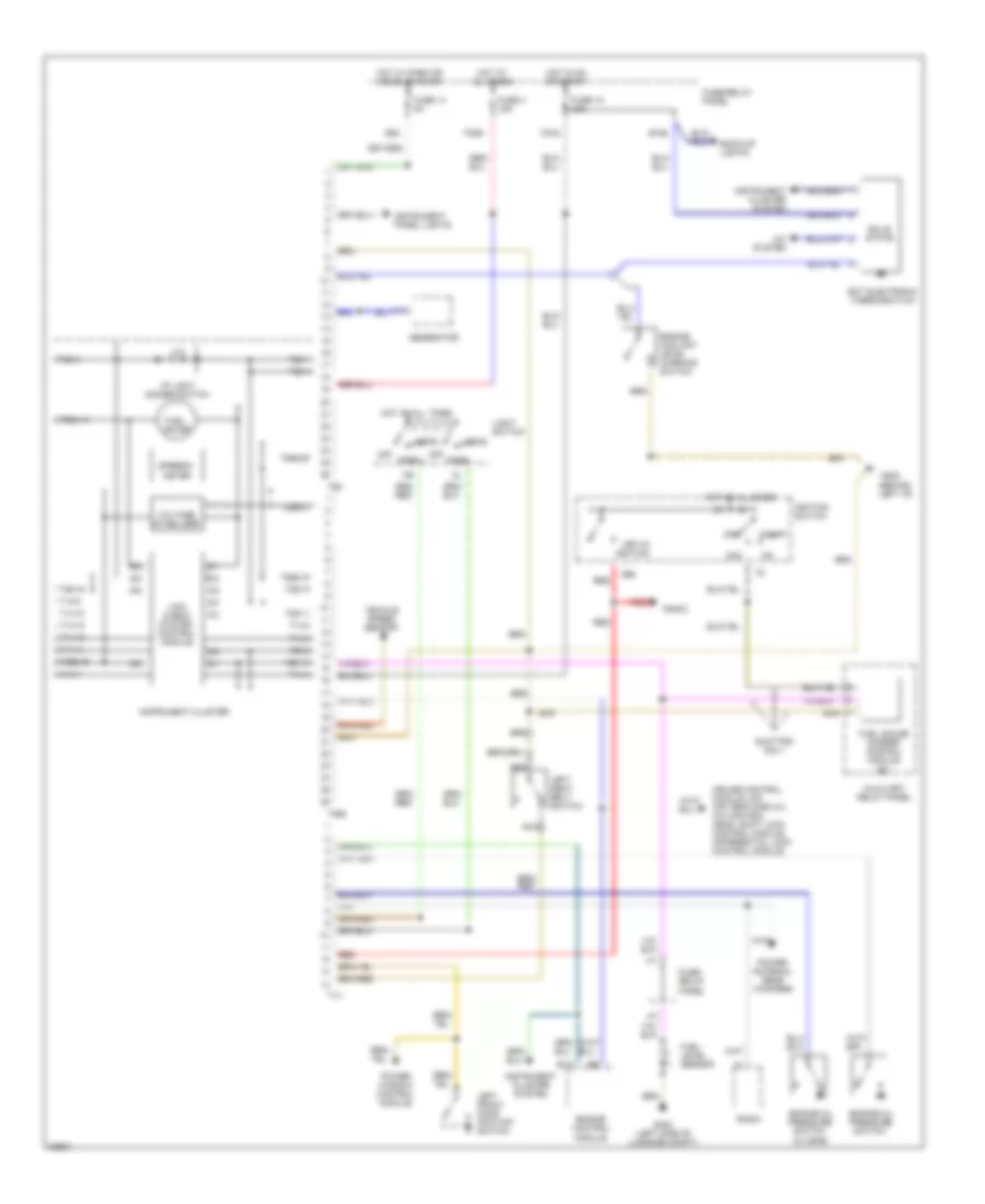
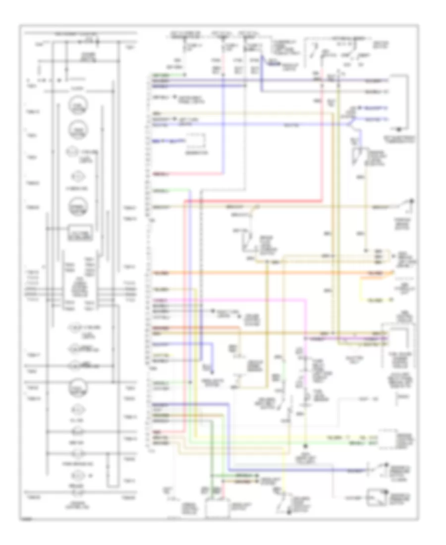
ПРИБОРНАЯ ПАНЕЛЬ
Электросхема панели приборов для Audi 90 1995
Электросхема панели приборов для Audi 90 1995 - Список элементов:
- (0.3 bar)
- (3 bulbs)
- (behind left side of i/p)
- 86s
- Abs control module
- Abs hydraulic unit
- Abs ind.
- Acc
- Air bag control ind.
- Air cond system
- Airbag control module
- Auxiliary relay panel (behind left side of i/p)
- B10
- B15a
- Back-up lights
- Brake fluid level warning switch
- C14
- C15a
- Clock
- Cruise control system
- Dimmer switch
- Driver's door contact switch
- Driver's seat belt switch
- Ect electronic thermoswitch
- Engine control module (ecm)
- Engine coolant level switch
- Engine oil pressure
- F30al
- Fuel gauge
- Fuel gauge damper control module
- Fuel level sensor
- Fuse 12 15a
- Fuse 14 5a
- Fuse 4 15a
- Fuse/ relay panel (left side plenum tray)
- Fuse/relay panel (left side plenum tray)
- G202
- G404 (near left taillight)
- Gen ind.
- Generator
- Headlight switch
- Headlight system
- Headlights system
- Hi beam ind.
- Hot at all times
- Hot w/ park or headlights on
- I58d
- Ignition switch
- Illum. lights
- Instrument cluster
- Instrument panel lights
- Key switch
- Left turn ind.
- Left turn lights
- Mil ind.
- Mini check system control module
- Nca
- Off
- Park brake ind.
- Parking brake switch
- Quattro only
- Radio
- Red
- Right turn ind.
- Right turn lights
- Speed- ometer
- Start
- Switch
- T14
- T14-10
- T14-12
- T14-13
- T14-14
- T14-3
- T14-4
- T14-7
- T14-8
- T14-9
- T26
- T26-1
- T26-10
- T26-13
- T26-19
- T26-2
- T26-22
- T26-23
- T26-25
- T26-3
- T26-5
- T26-8
- T26-9
- T26a
- T26a-10
- T26a-13
- T26a-15
- T26a-16
- T26a-17
- T26a-18
- T26a-20
- T26a-21
- T26a-23
- T26a-25
- T26a-26
- T5c/1
- T5c/2
- T5c/3
- T5c/5
- T6g/1
- T6g/2
- T6g/3
- T6g/4
- T6g/5
- T6g/6
- Tach- ometer
- Temp gauge
- Vehicle speed sensor
- Voltage stabilizer
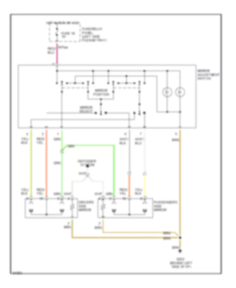
ПРИВОД ЗЕРКАЛ
Электросхема привода зеркал для Audi 90 1995
Электросхема привода зеркал для Audi 90 1995 - Список элементов:
- Defogger
- Driver's side mirror
- Fuse 18 5a
- Fuse/relay panel (left side plenum tray)
- G202 (behind left side of i/p)
- Hot in run or acc
- M75as
- Mirror adjustment switch
- Mirror position
- Mirror select
- Passenger's side mirror
- System
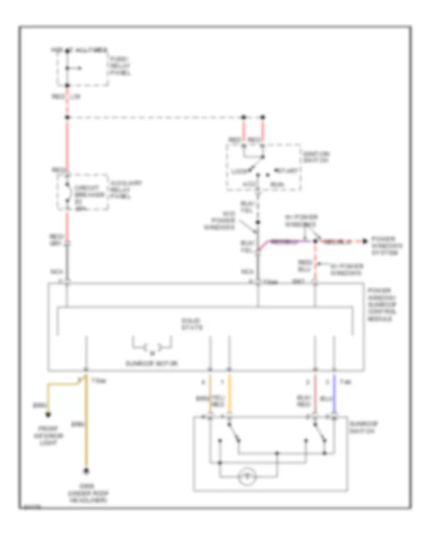
ПРИВОД ЛЮКА И КРЫШИ
Электросхема привода люка для Audi 90 1995
Электросхема привода люка для Audi 90 1995 - Список элементов:
- 8/87
- Acc
- Auxiliary relay panel
- Circuit breaker 20a
- Front interior light
- Fuse/ relay panel
- G908 (under roof headliner)
- Hot at all times
- Ignition switch
- L30
- Lock
- Nca
- Power window/ sunroof control module
- Power windows system
- Red
- Run
- Solid state
- Start
- Sunroof motor
- Sunroof switch
- T4k
- T6ae
- W/ power windows
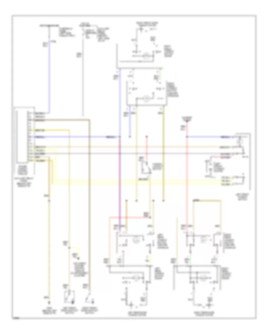
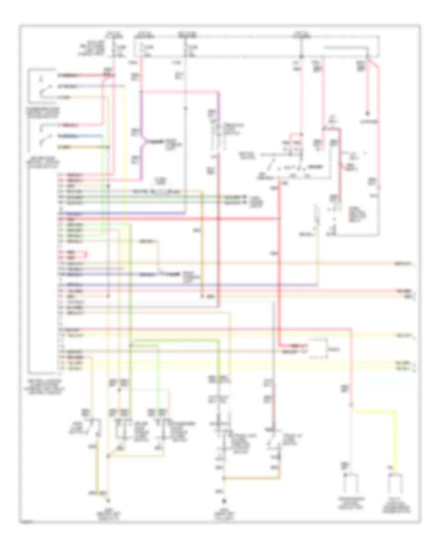
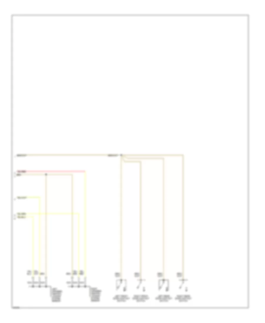
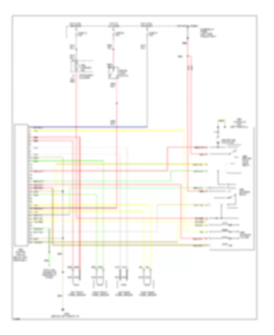
ПРИВОД СТЕКЛОПОДЪЕМНИКОВ
Электросхема стеклоподъемников для Audi 90 1995
Электросхема стеклоподъемников для Audi 90 1995 - Список элементов:
- All times
- Auxiliary relay panel (behind left side of i/p)
- Circuit breaker 20a
- Fuse/relay panel (left side plenum tray)
- G202 (behind left side of i/p)
- Hot at
- Hot in on or acc
- Left front door contact switch
- Left front window motor
- Left front window switch
- Left rear
- Left rear door window motor
- Left rear window switch (door)
- M75s
- Mini check system control module (in instrument cluster)
- Nca
- Power window control module
- Right front door contact switch
- Right front door window motor
- Right front window switch (center console)
- Right front window switch (door)
- Right rear
- Right rear door window motor
- Right rear window switch (door)
- Sunroof motor
- Window lockout switch
- Window switch (center console)
Противоугонная система Сигнализация
противоугонная и центральная схема захвата (1 из 2) для Audi 90 1995
противоугонная и центральная схема захвата (1 из 2) для Audi 90 1995 - Список элементов:
- (left side
- 3/k
- 7/30
- 86s
- A/t only
- Acc
- Alarm horn
- Alarm switch
- All times
- Auxiliary
- C15a
- Central locking/ alarm system/ interior light delay control module
- Control
- Driver door central locking system switch
- Driver door handle alarm switch
- E50a
- F30al
- F50z
- Front interior light
- Function
- Fuse 12a
- Fuse 15a
- G202 (behind left
- G404 (near left
- Hood
- Hot at
- Hot in on or start
- Ignition
- Key switch
- L30
- Module (tcm)
- Multi-
- Nca
- Off
- Park/ neutral position relay
- Passenger door central locking system switch
- Passenger door handle alarm switch
- Plenum tray)
- Radio
- Rear fog light switch
- Red
- Relay panel
- Side of i/p)
- Start
- Starter
- Switch
- Taillight)
- Transmission
- Transmission range switch
- Trunk lid alarm switch
- Trunk lock alarm/ central locking switch
- Turn/ hazard lights
противоугонная и центральная схема захвата (2 из 2) для Audi 90 1995
противоугонная и центральная схема захвата (2 из 2) для Audi 90 1995 - Список элементов:
- Left front door contact switch
- Left infrared central locking system sensor
- Left rear door contact switch
- Nca
- Right front door contact switch
- Right infrared central locking system sensor
- Right rear door contact switch
СИСТЕМА АНТИБЛОКИРОВОЧНОЙ ТОРМОЗНОЙ СИСТЕМЫ ABS
Электросхема антиблокировочной тормозной системы АБС (ABS), БУДУЩАЯ для Audi 90 1995
Электросхема антиблокировочной тормозной системы АБС (ABS), БУДУЩАЯ для Audi 90 1995 - Список элементов:
- (behind left side of i/p)
- (below left
- (left firewall)
- Abs
- Abs return flow pump
- Abs return flow pump relay
- Abs solenoid relay
- Abs solenoid valves
- Abs warning ind.
- All times
- Brake lamp switch
- Control
- Data link connector (near relay panel)
- Fuse 12 15a
- Fuse 29 10a
- Fuse 31 15a
- Fuse/relay panel (left side plenum tray)
- G202
- Hot at
- Hot at all times
- Hot in on or start
- Hydraulic
- Instrument cluster
- Left front wheel sensor
- Left rear wheel sensor
- Module
- Nca
- Rear seat)
- Red
- Red red
- Right front wheel sensor
- Right rear wheel sensor
- Unit
Электросхема антиблокировочной тормозной системы АБС (ABS), Quattro для Audi 90 1995
Электросхема антиблокировочной тормозной системы АБС (ABS), Quattro для Audi 90 1995 - Список элементов:
- (behind left side of i/p)
- (below left
- (left firewall)
- (left side
- Abs
- Abs control module
- Abs return flow pump
- Abs return flow pump relay
- Abs solenoid valve relay
- Abs solenoid valves
- Abs warning ind
- All times
- Brake lamp
- Data link connector (near relay panel)
- Differential lock control module
- Differential lock switch
- Display unit
- Fuse 12 15a
- Fuse 29 10a
- Fuse 31 15a
- Fuse/relay panel (left side plenum tray)
- G202
- G202 (left side of i/p)
- Hot at
- Hot at all times
- Hot in on or start
- Hydraulic
- Instrument cluster
- Interior lights system
- Left front wheel sensor
- Left rear wheel sensor
- Nca
- Of i/p)
- Rear diff lock ind
- Rear differential lock switch
- Rear seat)
- Red
- Red red
- Right front wheel sensor
- Right rear wheel sensor
- Speedometer
- Unit
СИСТЕМА КОНДИЦИОНЕРА
Автоматическая Системная Монтажная схема A/C-Heater (Со Схемой Автоматической коробки передач, A/T 1 для Audi 90 1995
Автоматическая Системная Монтажная схема A/C-Heater (Со Схемой Автоматической коробки передач, A/T 1 для Audi 90 1995 - Список элементов:
- (left side of i/p)
- 1995 vftc c
- A/c control head
- Air flow flap motor
- Auxiliary relay panel 2
- B10
- Battery (30)
- C10
- C11
- Central flap motor potentiometer
- Data link connector
- Engine control module
- Footwell/defrost flap motor potentiometer
- Fuse 15a
- Fuse 25a
- Fuse 30a
- Fuse 5a
- Fuse 60a
- Fuse/ relay panel
- G202 (left side of i/p)
- Hot at all times
- Hot w/ lights on
- Hot w/ load reduction relay energized (x)
- Ignition (15)
- Interior temperature sensor fan
- Temp regulator flap motor potentiometer
- Transmission control module
Автоматическая Системная Монтажная схема A/C-Heater (Со Схемой Автоматической коробки передач, A/T 2 для Audi 90 1995
Автоматическая Системная Монтажная схема A/C-Heater (Со Схемой Автоматической коробки передач, A/T 2 для Audi 90 1995 - Список элементов:
- (in battery box)
- (left side of i/p)
- (left side of i/p) g202
- (near compressor)
- 1995 vftc c
- A/c compressor clutch
- A/c compressor clutch relay
- A/c compressor speed sensor
- A/c refrigerant high pressure switch
- A/c refrigerant low pressure switch
- Ambient temperature sensor
- Blower motor
- Coolant fan control relay (in fuse/relay panel)
- Coolant fan control thermo switch
- Coolant fan resistors
- Coolant fans
- Digital outside air temperature display
- Electronic thermo switch
- Fresh air blower control module
- Fresh air duct temperature sensor
- Fresh air recirculating flap valve
- G202
- G202 (left side of i/p)
- Instrument cluster
- Interior temperature sensor (headliner)
- Interior temperature sensor (instrument cluster)
- Low coolant switch
- Protection diode
- Second speed coolant fan control relay
- Third speed coolant fan control relay
Автоматическая Системная Монтажная схема A/C-Heater (Со Схемой Ручной передачи, M/T 1 2) для Audi 90 1995
Автоматическая Системная Монтажная схема A/C-Heater (Со Схемой Ручной передачи, M/T 1 2) для Audi 90 1995 - Список элементов:
- (left side of i/p)
- 1995 vftc c
- A/c control head
- Air flow flap motor
- Auxiliary relay panel 2
- B10
- Battery (30)
- C10
- C11
- Central flap motor potentiometer
- Data link connector
- Engine control module
- Footwell/defrost flap motor potentiometer
- Fuse 15a
- Fuse 25a
- Fuse 30a
- Fuse 5a
- Fuse 60a
- Fuse/ relay panel
- G202 (left side of i/p)
- Hot at all times
- Hot w/ lights on
- Hot w/ load reduction relay energized (x)
- Ignition (15)
- Interior temperature sensor fan
- Temp regulator flap motor potentiometer
- Transmission control module
Автоматическая Системная Монтажная схема A/C-Heater (Со Схемой Ручной передачи, M/T 2 2) для Audi 90 1995
Автоматическая Системная Монтажная схема A/C-Heater (Со Схемой Ручной передачи, M/T 2 2) для Audi 90 1995 - Список элементов:
- (in battery box)
- (left side of i/p)
- (left side of i/p) g202
- (near compressor)
- 1995 vftc c
- A/c compressor clutch
- A/c compressor clutch relay
- A/c compressor speed sensor
- A/c refrigerant high pressure switch
- A/c refrigerant low pressure switch
- Ambient temperature sensor
- Blower motor
- Coolant fan control relay (in fuse/relay panel)
- Coolant fan control thermo switch
- Coolant fan resistors
- Coolant fans
- Digital outside air temperature display
- Electronic thermo switch
- Fresh air blower control module
- Fresh air duct temperature sensor
- Fresh air recirculating flap valve
- G202
- G202 (left side of i/p)
- Instrument cluster
- Interior temperature sensor (headliner)
- Interior temperature sensor (instrument cluster)
- Low coolant switch
- Protection diode
- Second speed coolant fan control relay
Электросхема кондиционера с ручный управлением, A/T для Audi 90 1995
Электросхема кондиционера с ручный управлением, A/T для Audi 90 1995 - Список элементов:
- (behind left side of i/p) g202
- (in battery box) g100
- (near compressor)
- (not used)
- 1995 vftc c
- A/c clutch control module
- A/c compressor clutch
- A/c compressor speed sensor
- A/c flap solenoid
- A/c refrig- erant low pressure switch
- A/c refrigerant
- A/c refrigerant high pressure switch
- A/c switch
- Ambient temper- ature switch
- Auxiliary relay panel
- B10
- Blower motor
- Blower resistors
- Blower switch
- C10
- C11
- Coolant fan
- Coolant fan control relay
- Coolant fan control series resistors
- Coolant fan control thermoswitch
- Data link connector
- Engine control module
- Engine coolant temperature electronic thermo switch
- Engine coolant temperature gauge
- Fuse 15a
- Fuse 25a
- Fuse 30a
- Fuse 60a
- Fuse/ relay panel
- G202 (behind left side of i/p)
- Heater fan
- High pressure switch
- Hot at all times
- Hot with load reduction relay energized (x)
- Ignition (15)
- Interior lights system
- Off
- Protection diode
- Relay
- Second speed coolant fan control relay
- Third speed coolant fan control relay
- Transmission control module
- Wire distributor
Электросхема кондиционера с ручный управлением, M/T для Audi 90 1995
Электросхема кондиционера с ручный управлением, M/T для Audi 90 1995 - Список элементов:
- (behind left side of i/p)
- (left side i/p)
- (left side of i/p)
- (near compressor)
- 1995 vftc c
- A/c compressor clutch
- A/c compressor clutch control module
- A/c compressor speed sensor
- A/c flap solenoid
- A/c refrig- erant low pressure switch
- A/c refrigerant
- A/c refrigerant high pressure switch
- A/c switch
- Auxiliary relay panel
- B10
- Blower motor
- Blower resistors
- Blower switch
- C10
- C11
- Coolant fan control relay (in fuse/ relay panel)
- Coolant fan resistors
- Coolant fan thermo switch
- Data link connector
- Diode
- Electronic thermo switch
- Engine control module
- Fuse 15a
- Fuse 30a
- Fuse 60a
- Fuse/ relay panel
- G202
- G202 (behind left side of i/p)
- Heater fan relay (in fuse/ relay panel)
- Hot at all times
- Hot with load reduction relay energized (x)
- Ignition (15)
- Instru- ment cluster
- Interior lights system
- Low coolant switch
- Off
- Outside temp switch
- Pressure safety switch
- Protection diode
- Third speed coolant fan ctrl relay
- Trans- mission control module
СИСТЕМА КРУИЗКОНТРОЛЯ
Электросхема системы круизконтроля для Audi 90 1995
Электросхема системы круизконтроля для Audi 90 1995 - Список элементов:
- Auxiliary relay panel
- B16
- Brake light switch
- Brake vacuum vent valve
- Cabriolet
- Cabriolet & 90 series a/t
- Cluster
- Clutch vacuum vent valve
- Connector station
- Control module
- Convertible top control module
- Cruise control module
- Cruise control switch
- Cruise control vacuum pump
- Engine control module
- Except cabriolet
- Fuse 10a
- Fuse 15a
- Fuse 5a
- Fuse/ relay panel
- G200 (behind left side of i/p)
- Hot at all times
- Hot in on or start
- Instrument
- Series m/t
- Speedo- meter
- T10
- T26a
- Transmission
- Vehicle speed output
- Wire connector (behind i/p)
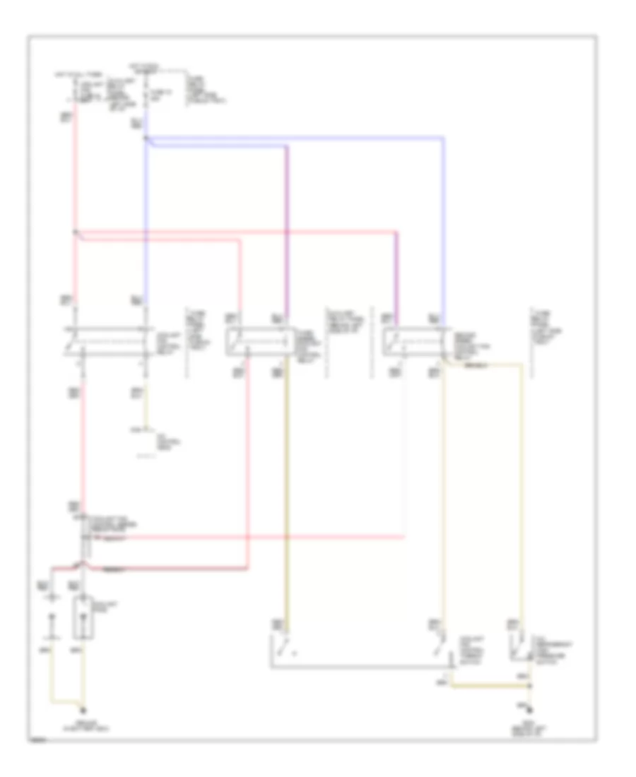
СИСТЕМА ОХЛАЖДЕНИЯ
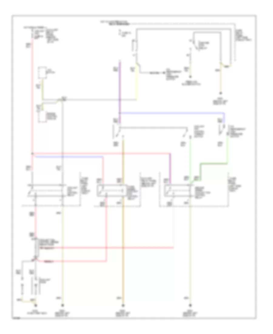
Электросхема системы охлаждения, A/T С Авто A/C для Audi 90 1995
Электросхема системы охлаждения, A/T С Авто A/C для Audi 90 1995 - Список элементов:
- (behind left side of i/p)
- (in battery box)
- (left side plenum tray)
- A/c control head
- A/c refrigerant high pressure switch
- Auxiliary
- Coolant fan fuse 42 60a
- Coolant fan control relay
- Coolant fan control series resistance
- Coolant fan control thermo- switch
- Coolant fans
- D16
- Fuse 15 25a
- Fuse/ relay panel
- Fuse/ relay panel (left side plenum tray)
- G202
- Ground
- Hot at all times
- Hot in run
- Or accy
- Relay panel
- Second speed coolant fan control relay
- Third speed coolant fan control relay
Электросхема системы охлаждения, A/T С Ручное управление A/C для Audi 90 1995
Электросхема системы охлаждения, A/T С Ручное управление A/C для Audi 90 1995 - Список элементов:
- (behind left side of i/p)
- (in battery box)
- (left side plenum tray)
- A/c
- A/c refrigerant high pressure switch
- Auxiliary
- C11
- Coolant fan fuse 42 60a
- Coolant fan control relay
- Coolant fan control series resistance
- Coolant fan control thermo- switch
- Coolant fans
- Engine control module
- Fresh air blower switch
- Fuse 15 25a
- Fuse/ relay panel
- Fuse/ relay panel (left side plenum tray)
- G100
- G202
- Heater fan relay
- Hot at all times
- Hot w/load reduction
- Relay energized
- Relay panel
- Second speed coolant fan control relay
- Switch
- Third speed coolant fan control relay
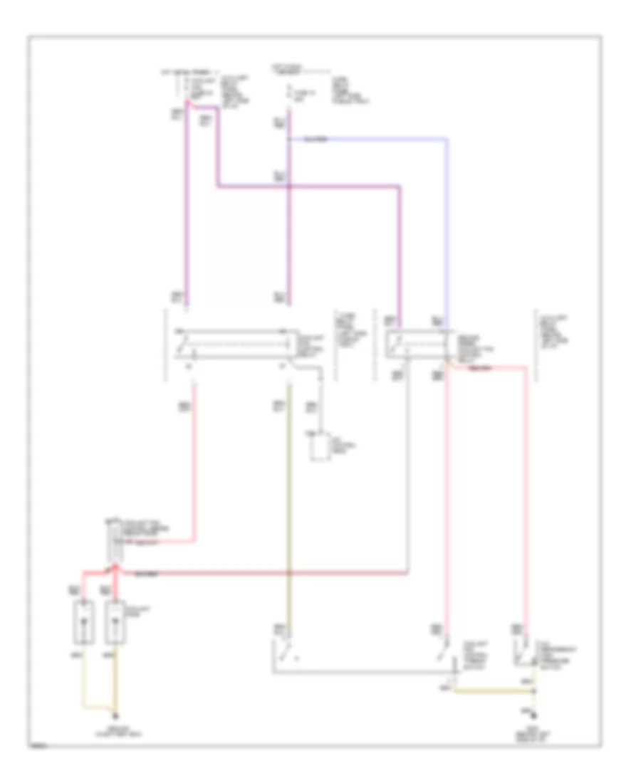
Электросхема системы охлаждения, M/T С Авто A/C для Audi 90 1995
Электросхема системы охлаждения, M/T С Авто A/C для Audi 90 1995 - Список элементов:
- (behind left side of i/p)
- (in battery box)
- (left side plenum tray)
- A/c control head
- A/c refrigerant high pressure switch
- Auxiliary
- Coolant fan fuse 42 60a
- Coolant fan control relay
- Coolant fan control series resistance
- Coolant fan control thermo- switch
- Coolant fans
- D16
- Fuse 15 25a
- Fuse/ relay panel
- Fuse/ relay panel (left side plenum tray)
- G202
- Ground
- Hot at all times
- Hot in run
- Or accy
- Relay panel
- Second speed coolant fan control relay
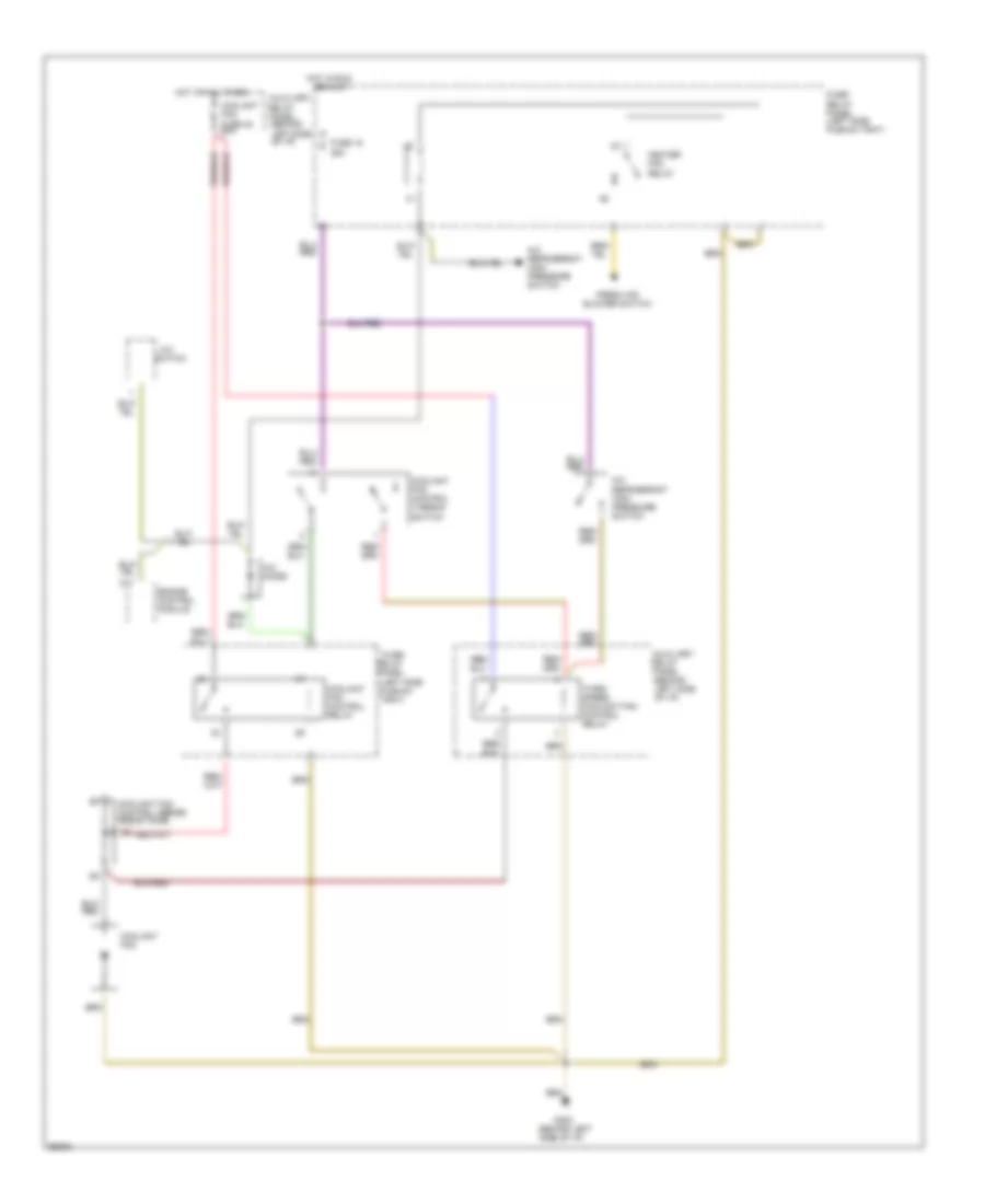
Электросхема системы охлаждения, M/T С Ручное управление A/C для Audi 90 1995
Электросхема системы охлаждения, M/T С Ручное управление A/C для Audi 90 1995 - Список элементов:
- (behind left side of i/p)
- (left side plenum tray)
- A/c
- A/c diode
- A/c refrigerant high pressure switch
- Auxiliary
- C11
- Coolant fan
- Coolant fan fuse 42 60a
- Coolant fan control relay
- Coolant fan control series resistance
- Coolant fan control thermo- switch
- Engine control module
- Fresh air blower switch
- Fuse 15 25a
- Fuse/ relay panel
- Fuse/ relay panel (left side plenum tray)
- G202
- Heater fan relay
- Hot at all times
- Hot in run
- Or accy
- Relay panel
- Switch
- Third speed coolant fan control relay
СИСТЕМА ПЕРЕДАЧИ ДАННЫХ
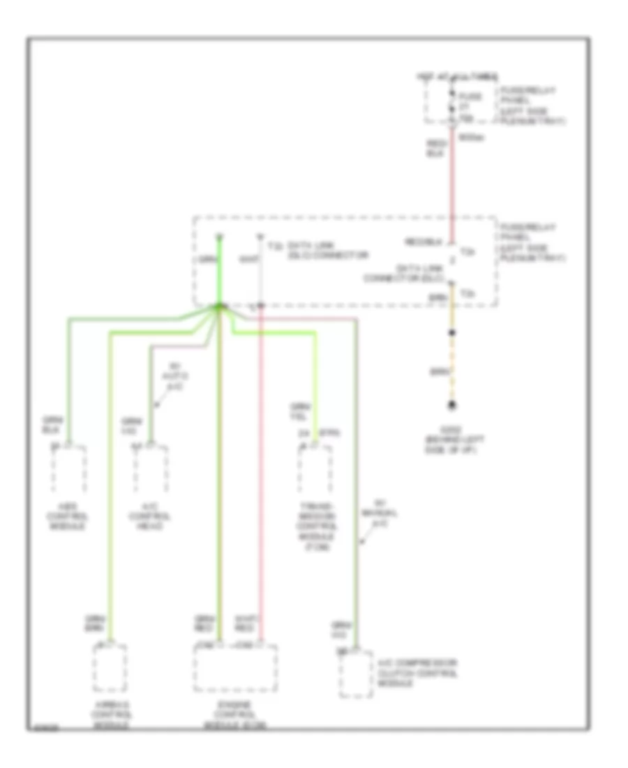
Электросхема линии передачи данных CAN для Audi 90 1995
Электросхема линии передачи данных CAN для Audi 90 1995 - Список элементов:
- (01n)
- (behind left side of i/p)
- (left side plenum tray)
- 3/d
- A/c compressor clutch control module
- A/c control head
- Abs control module
- Airbag control module
- C12
- C13
- Data link (dlc) connector
- Data link connector (dlc)
- Engine control module (ecm)
- Fuse 10a
- Fuse/relay panel
- G202
- Hot at all times
- M30ac
- T2x
- T2z
- Trans- mission control module (tcm)
- W/ auto a/c
- W/ manual a/c
СИСТЕМА УПРАВЛЕНИЯ ДВИГАТЕЛЯ
2.8L
2.8L, монтажная схема (кабриолет и 90 2.8L схема 1 из 2) для Audi 90 1995
2.8L, монтажная схема (кабриолет и 90 2.8L схема 1 из 2) для Audi 90 1995 - Список элементов:
- (on intake manifold)
- A10
- A11
- A12
- Auxiliary fuse holder
- B10
- B11
- B12
- B13
- B14
- B15
- B16
- B17
- B18
- B19
- B20
- Bat(30)
- C15a
- Cabriolet
- Closed throttle position switch/ throttle position sensor
- Connector station in auxiliary
- Fuse 15a
- Fuse 20a
- Fuse/ relay panel
- G131
- Ign (15)
- Ignition coil 1
- Ignition coil 2
- Ignition coil 3
- Instrument cluster
- Knock sensor #1
- Knock sensor #2
- L30
- Malfunction indicator lamp (mil)
- Mass air flow sensor
- Mfi engine control module
- Mini-check system control module
- Nca
- Power output stage
- Red
- Shift lock control module
- Solid state
- Spark plugs 1 & 6
- Spark plugs 2 & 4
- Spark plugs 3 & 5
- Speedo- meter
- T14
- T26
- T26a
- Tacho- meter
- Transmission control module
2.8L, монтажная схема (кабриолет и 90 2.8L схема 2 из 2) для Audi 90 1995
2.8L, монтажная схема (кабриолет и 90 2.8L схема 2 из 2) для Audi 90 1995 - Список элементов:
- (left i/p)
- (on intake manifold)
- 87a
- A/c system
- Auxiliary fuse holder
- Bat(30)
- C1
- C10
- C11
- C12
- C13
- C14
- C15
- C16
- Crank- shaft position sensor
- D10
- D11
- D12
- D13
- D14
- D15
- D16
- Data link connectors
- Egr temperature sensor
- Egr vacuum regulator solenoid valve
- Engine coolant temperature sensor
- Engine speed sensor
- Evaporative emission canister purge regulator valve
- Fuel injectors
- Fuel pump
- Fuel pump relay
- Fuse 10a
- Fuse 15a
- Fuse 20a
- Fuse/ relay panel
- G131
- G200
- G200 (left i/p)
- G404 (left trunk)
- H87f
- Hall sensor
- Idle air control valve
- Ign(15)
- Intake manifold change- over valve
- M30ac
- Mfi engine control module
- Nca
- Oxygen
- Oxygen sensor 1 heater
- Oxygen sensor 2
- Oxygen sensor 2 heater
- Red
- Sensor 1
- Solid state
- T2x
- T2z
- Wire distributors for data link connector
Система Фар
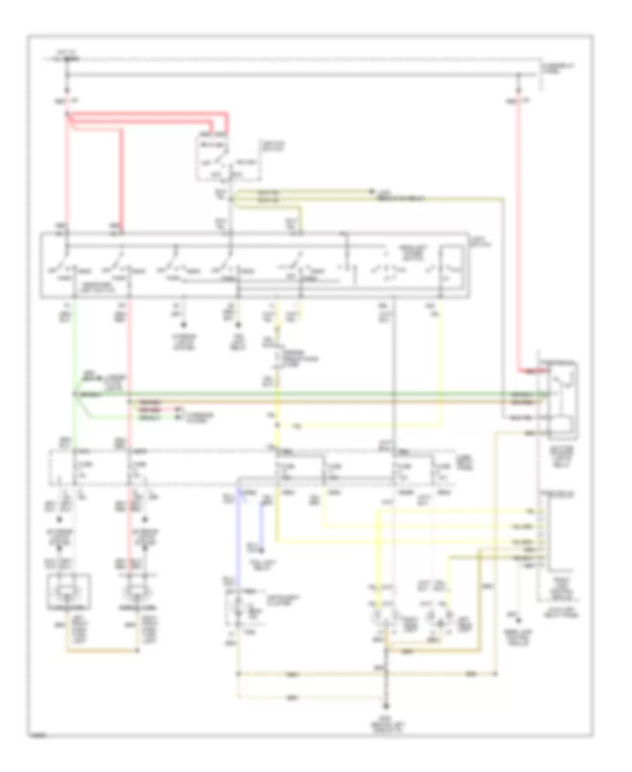
схема противотуманных фар, С DRL для Audi 90 1995
схема противотуманных фар, С DRL для Audi 90 1995 - Список элементов:
- (behind left side of i/p)
- (near left taillight)
- 56a
- 75n
- Acc
- All times
- C56ak
- D56ar
- F55
- Fog light relay
- Fog light switch
- Ftp
- Fuse 10a
- Fuse 15a
- Fuse/relay panel
- G202
- G404
- G85n
- G86n
- Head
- Head/park light switch
- Headlight dimmer switch
- Hi beam indicator
- Hot at
- Hot in on or acc
- I56a
- Ignition switch
- Interior lights system
- L30
- Left front fog light
- Light switch
- M75s
- Off
- Park
- Rear fog light
- Rear fog light switch
- Red
- Right front fog light
- Right head- light
- Run
- Start
Электросхема фар и противотуманок, без DRL для Audi 90 1995
Электросхема фар и противотуманок, без DRL для Audi 90 1995 - Список элементов:
- (behind left side of i/p)
- (near left taillight)
- 56a
- 56b
- 75n
- Acc
- All times
- C56ak
- D56al
- D56ar
- D56bl
- D56br
- F55
- F56b
- Fog light relay
- Fog light switch
- Ftp
- Fuse 10a
- Fuse 15a
- Fuse/ relay panel
- G202
- G404
- G85n
- G86n
- Head
- Head/park light switch
- Headlight dimmer switch
- Hi beam ind.
- Hot at
- Hot in on or acc
- I56a
- Ignition switch
- Instrument cluster
- Interior lights system
- L30
- Left front fog light
- Left head- light
- Light switch
- M75s
- Off
- Park
- Rear fog light
- Rear fog light switch
- Red
- Right front fog light
- Right head- light
- Run
- Start
- T26a
Электросхема фар, С DRL для Audi 90 1995
Электросхема фар, С DRL для Audi 90 1995 - Список элементов:
- (behind left side of i/p)
- (position 10)
- (position 15)
- 56a
- 56b
- Acc
- All times
- Auxiliary relay panel
- C56ak
- D 58l
- D56ar
- D56al
- D56bl
- D56br
- Daytime running lights relay
- E 58r
- Exterior lights system
- F56b
- F57l
- Fog light relay
- Front lamp control module
- Ftp
- Fuse 10a
- Fuse 5a
- Fuse/ relay panel
- Fuse/relay panel
- G202
- G57r
- H 58l
- H 58r
- Head
- Head/park light switch
- Headlight dimmer switch
- Hi beam ind.
- Hot at
- I56a
- Ignition switch
- Instrument cluster
- Interior lights system
- J30
- L30
- Left front park/ turn light
- Left head- light
- License plate lights
- Light switch
- Load reduction relay
- Off
- Park
- Rear lamp control module
- Red
- Right front park/ turn light
- Right head- light
- Run
- Series resistance wire
- Start
- T26a
- Turn
- Warnings system
СИСТЕМЫ СИДЕНИЙ
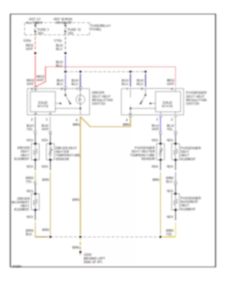
Электросхема подогрева сидений для Audi 90 1995
Электросхема подогрева сидений для Audi 90 1995 - Список элементов:
- All times
- C15a
- Driver backrest heat element
- Driver seat heat element
- Driver seat heat regulating switch
- Driver seat heater temperature sensor
- Fuse 12 15a
- Fuse 3 30a
- Fuse/relay panel
- G202 (behind left side of i/p)
- G30a
- Hot at
- Hot in run or start
- Nca
- Passenger backrest heat element
- Passenger seat heat element
- Passenger seat heat regulating switch
- Passenger seat heater temperature sensor
- Solid state
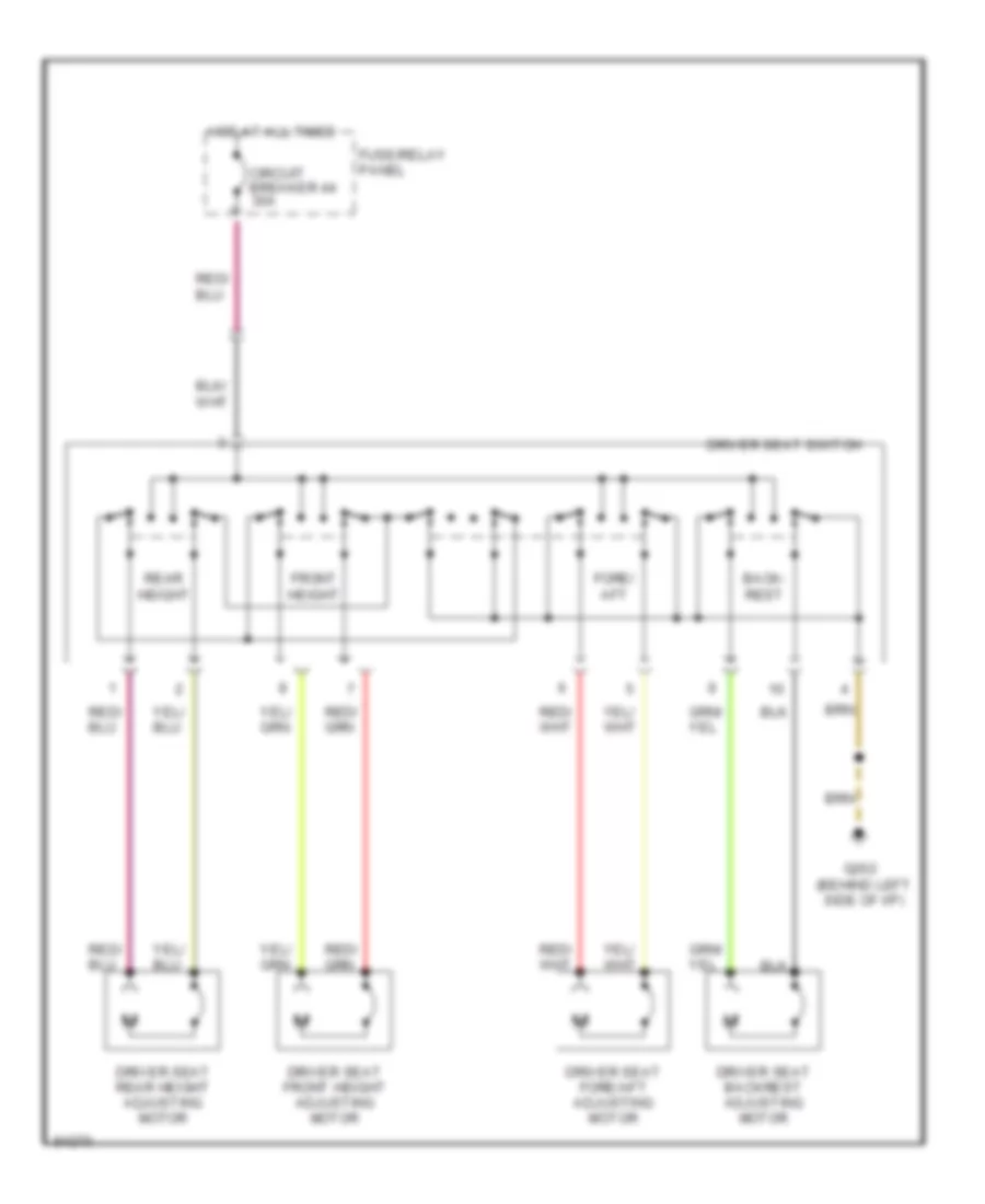
Электросхема привода сидений левой стороны для Audi 90 1995
Электросхема привода сидений левой стороны для Audi 90 1995 - Список элементов:
-
- Back- rest
- Circuit breaker 44 30a
- Driver seat backrest adjusting motor
- Driver seat fore/aft adjusting motor
- Driver seat front height adjusting motor
- Driver seat rear height adjusting motor
- Driver seat switch
- Fore/ aft
- Front height
- Fuse/relay panel
- G202 (behind left side of i/p)
- Hot at all times
- Rear height
Стартер Генератор
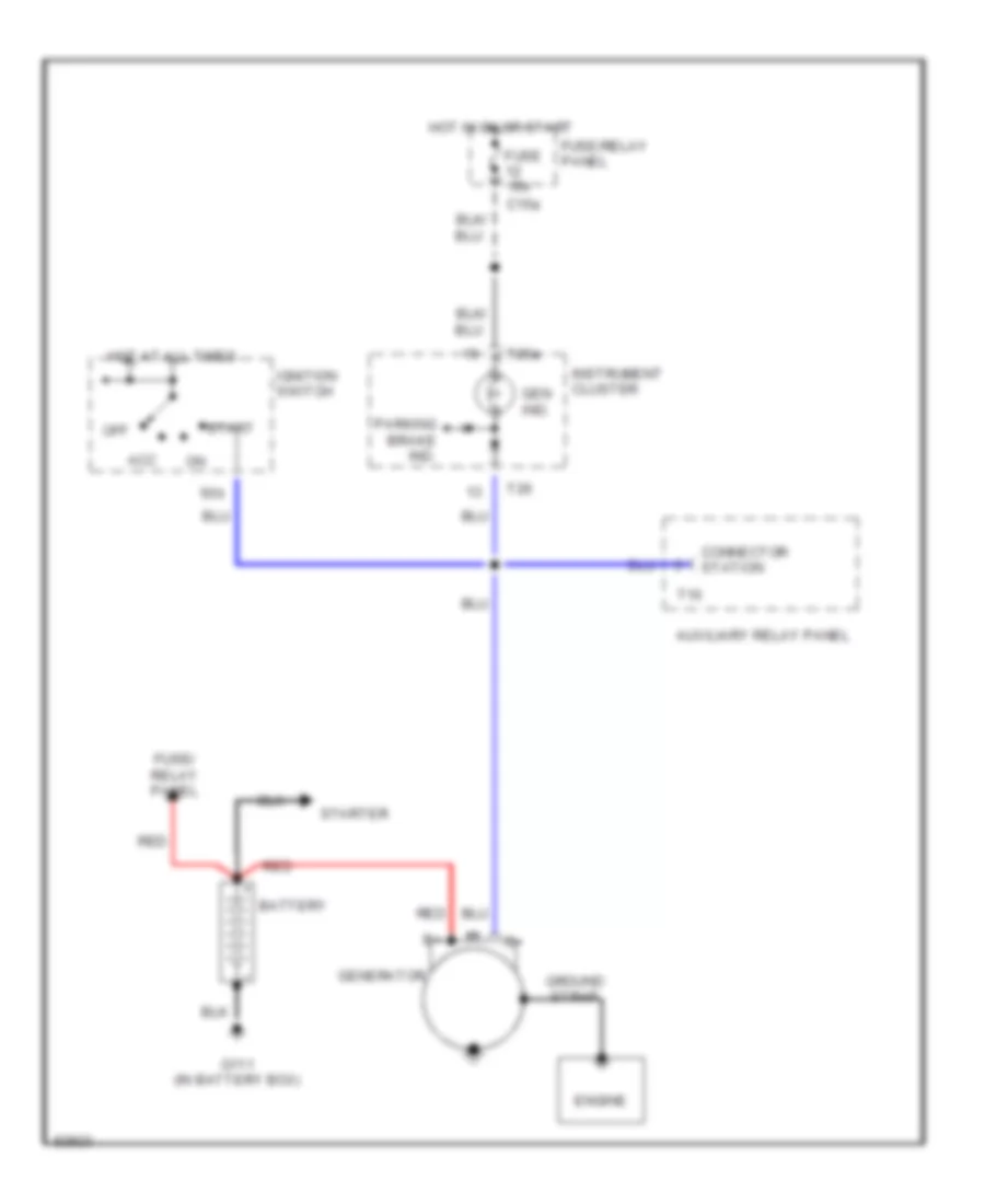
Электросхема Генератора для Audi 90 1995
Электросхема Генератора для Audi 90 1995 - Список элементов:
- 50b
- Acc
- Auxiliary relay panel
- Battery
- C15a
- Connector station
- Engine
- Fuse 15a
- Fuse/ relay panel
- Fuse/relay panel
- G111 (in battery box)
- Gen ind.
- Generator
- Ground strap
- Hot at all times
- Hot in on or start
- Ignition switch
- Instrument cluster
- Off
- Parking brake ind.
- Red
- Start
- Starter
- T10
- T26
- T26a
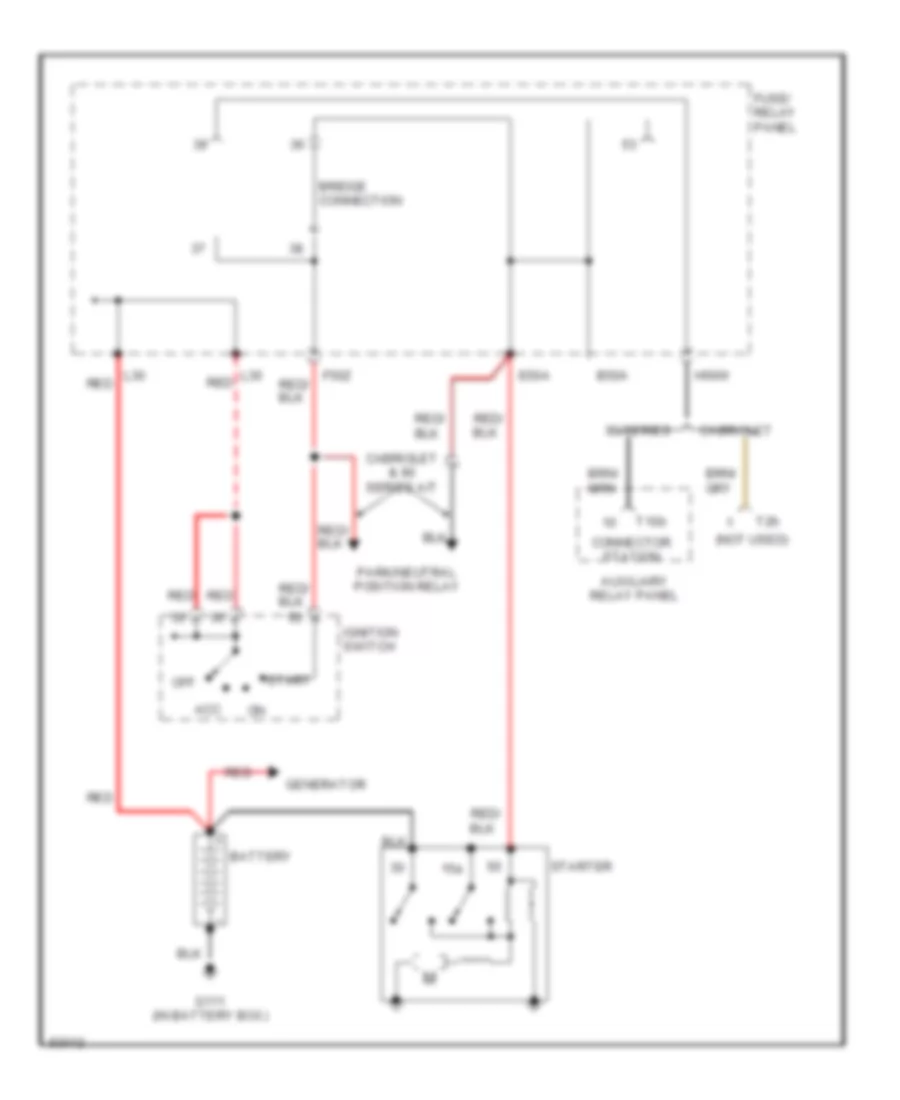
Электросхема стартера для Audi 90 1995
Электросхема стартера для Audi 90 1995 - Список элементов:
- (not used)
- 15a
- 90 series
- Acc
- Auxiliary relay panel
- B50a
- Battery
- Bridge
- Cabriolet
- Cabriolet & 90 series a/t
- Connection
- Connector station
- E50a
- F50z
- Fuse/ relay panel
- G111 (in battery box)
- Generator
- H50w
- Ignition switch
- L30
- L30 red
- Off
- Park/neutral position relay
- Red
- Start
- Starter
- T10b
- T2h
Стеклоочистители и Стеклоомыватели Дворники
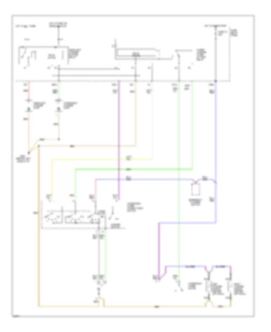
Электросхема стеклоочистителя, дворников и омывателя для Audi 90 1995
Электросхема стеклоочистителя, дворников и омывателя для Audi 90 1995 - Список элементов:
- B53c
- C31b
- C53c
- C53e
- Emergency
- Flasher switch
- Fuse 15 25a
- Fuse/ relay panel
- G202 (behind left side of i/p)
- G31
- Headlight washer pump
- Headlight washer system relay
- Hot at all times
- Hot in on or start
- Hot w/ park or headlights on
- I75aw
- Left washer nozzle heater (optional)
- Nca
- Red
- Right washer nozzle heater (optional)
- Solid state
- Washer switch
- Windshield washer pump
- Windshield wiper intermittent switch
- Windshield wiper motor
- Wiper switch
- Wiper/ washer inter- mittent relay
ЦЕНТРАЛЬНЫЙ ЗАМОК
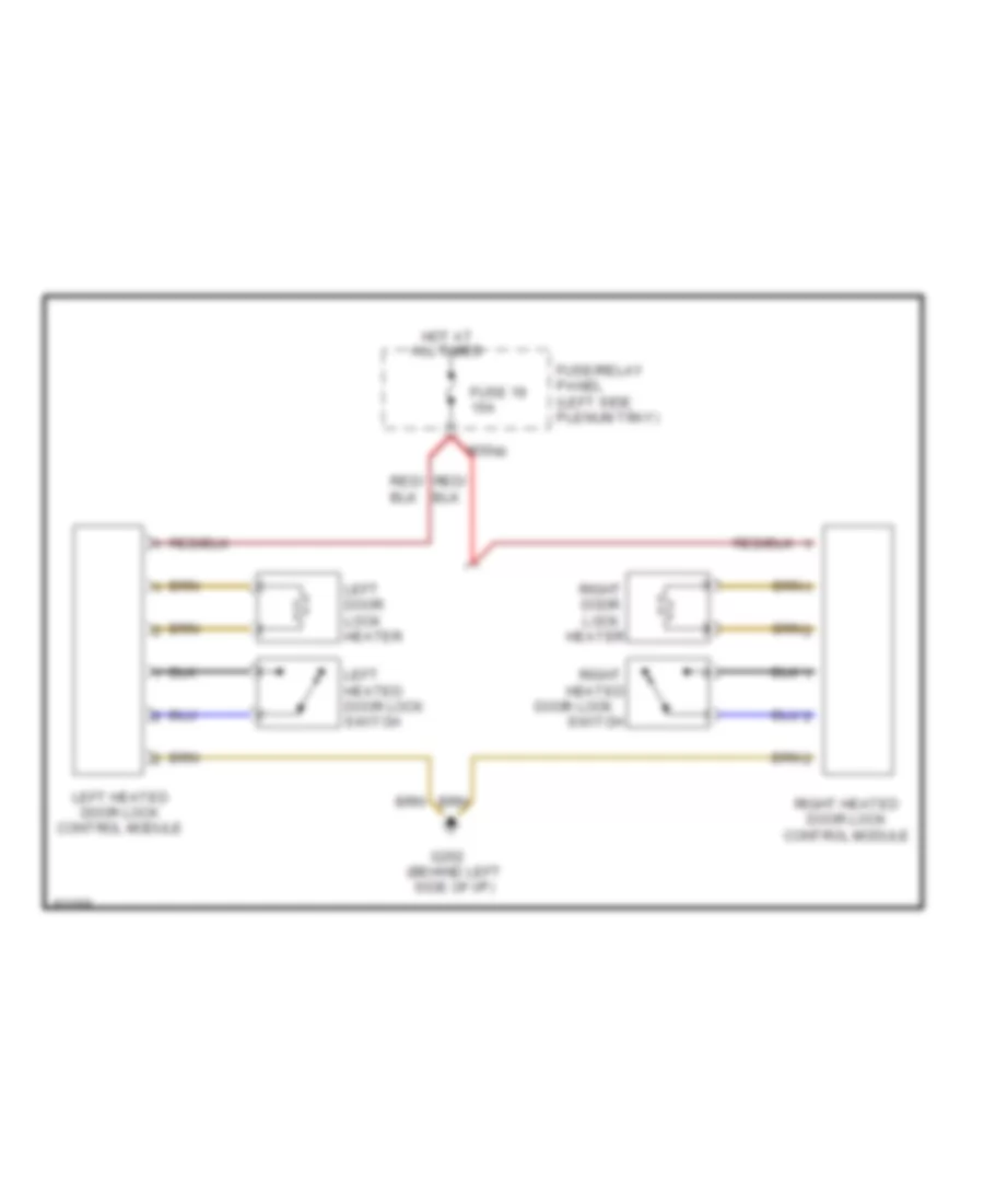
горячая дверь захватывает схему для Audi 90 1995
горячая дверь захватывает схему для Audi 90 1995 - Список элементов:
- All times
- Door lock
- Fuse 19 15a
- Fuse/relay panel (left side plenum tray)
- G202 (behind left side of i/p)
- Heated
- Heater
- Hot at
- Left door lock heater
- Left heated door lock control module
- Left heated door lock switch
- M30az
- Right
- Right door lock
- Right heated door lock control module
- Switch

 Čeština
 Dansk
Dansk Deutsch
 Ελληνικά
 English
 Español
 Suomi
Suomi Français
 Français
 עברית
עברית Hrvatski
 Magyar
 Italiano
 日本語
日本語 한국어
한국어 Nederlands
 Polski
 Português
 Português
 Română
 Русский
 Slovenčina
 Slovenščina
 Svenska
 Türkçe
 中文 (中国)