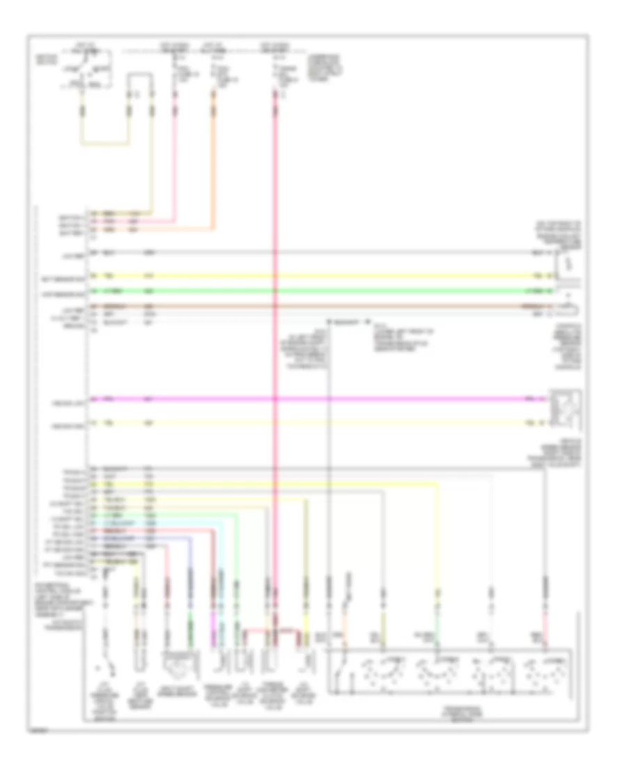
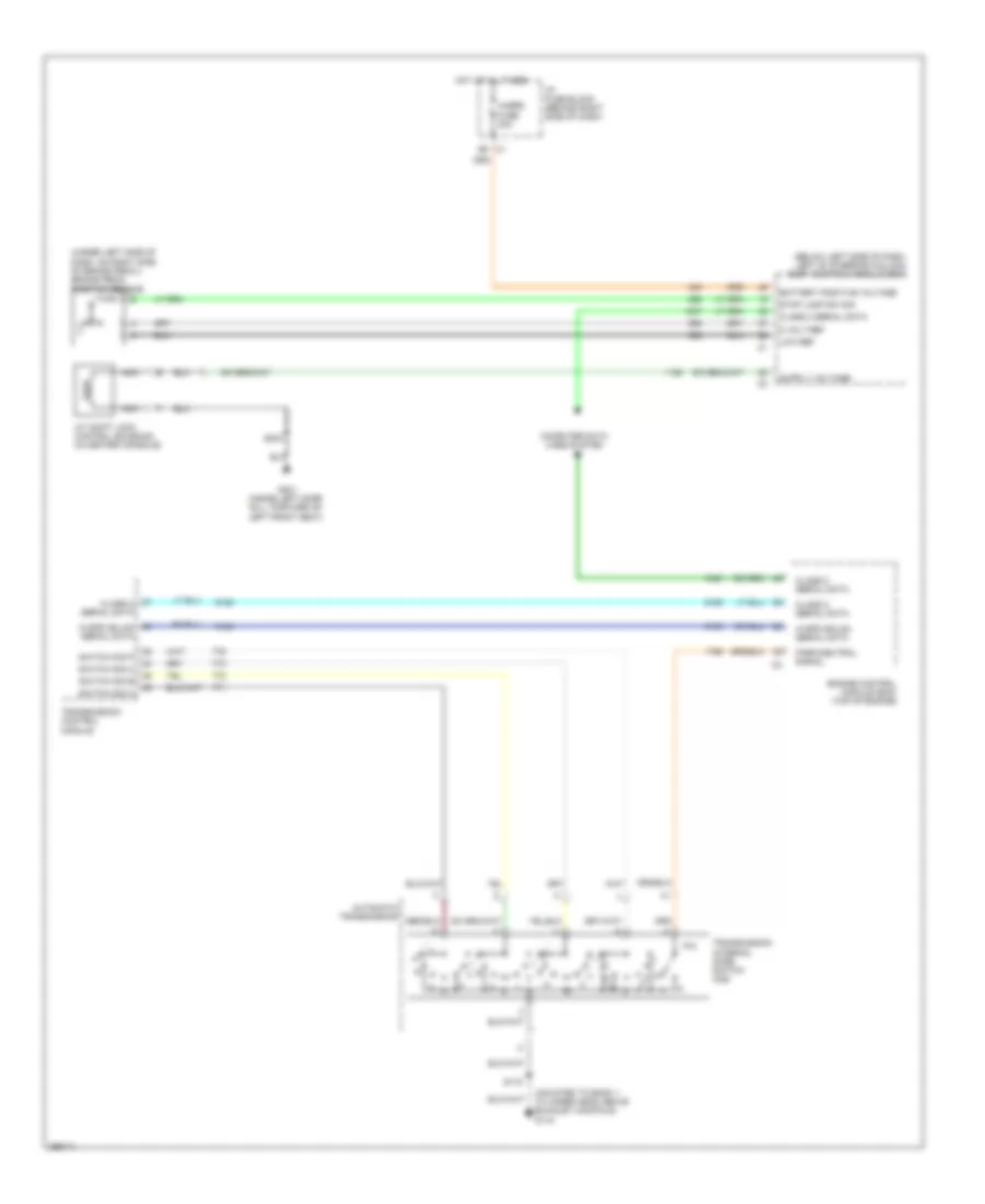
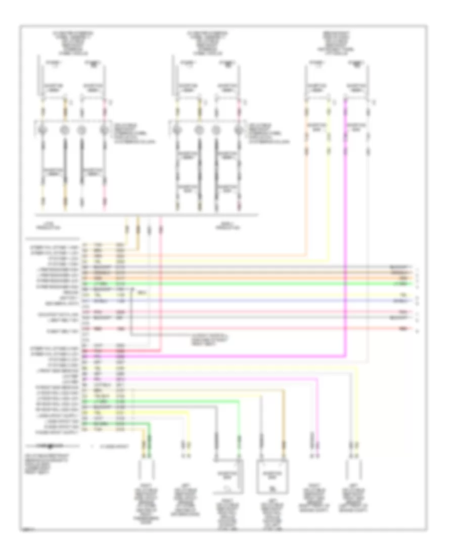
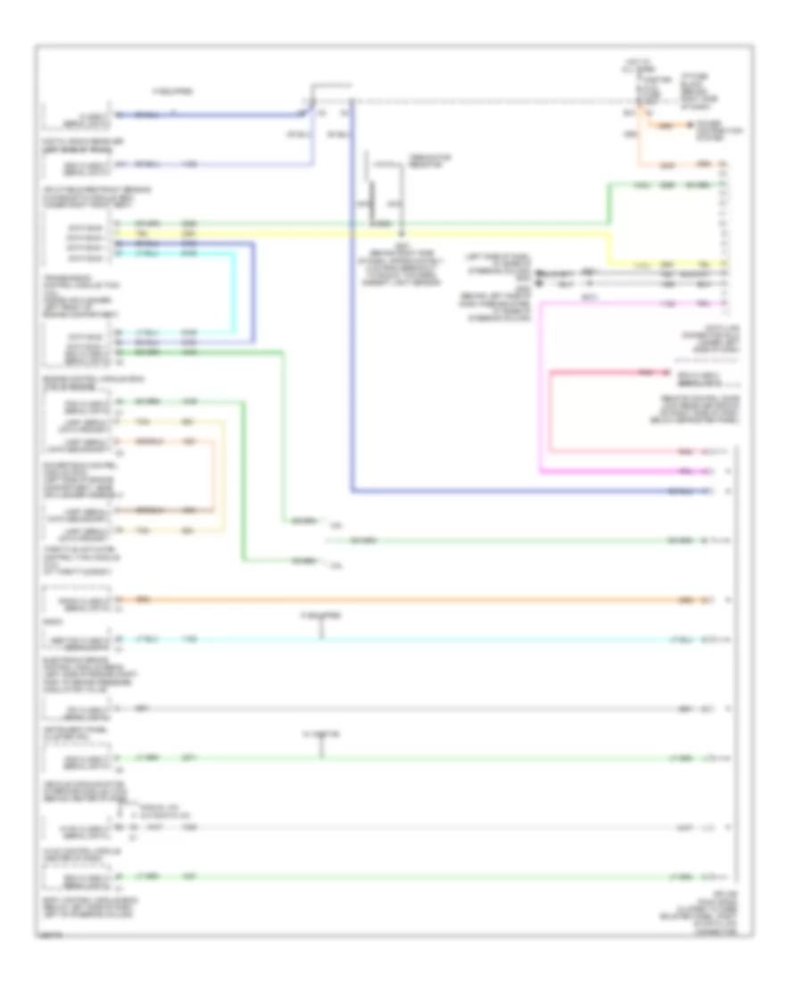
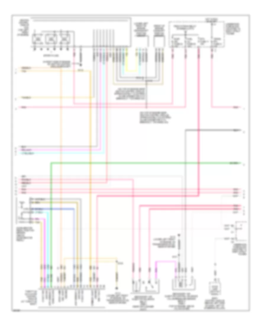
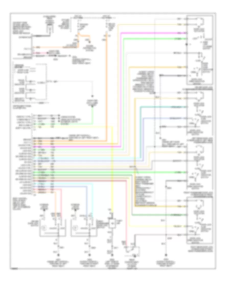
Автомтическая коробка Передач (АКПП) Полная привод (4WD) Блокировка Дифференциала
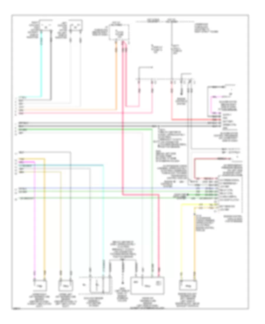
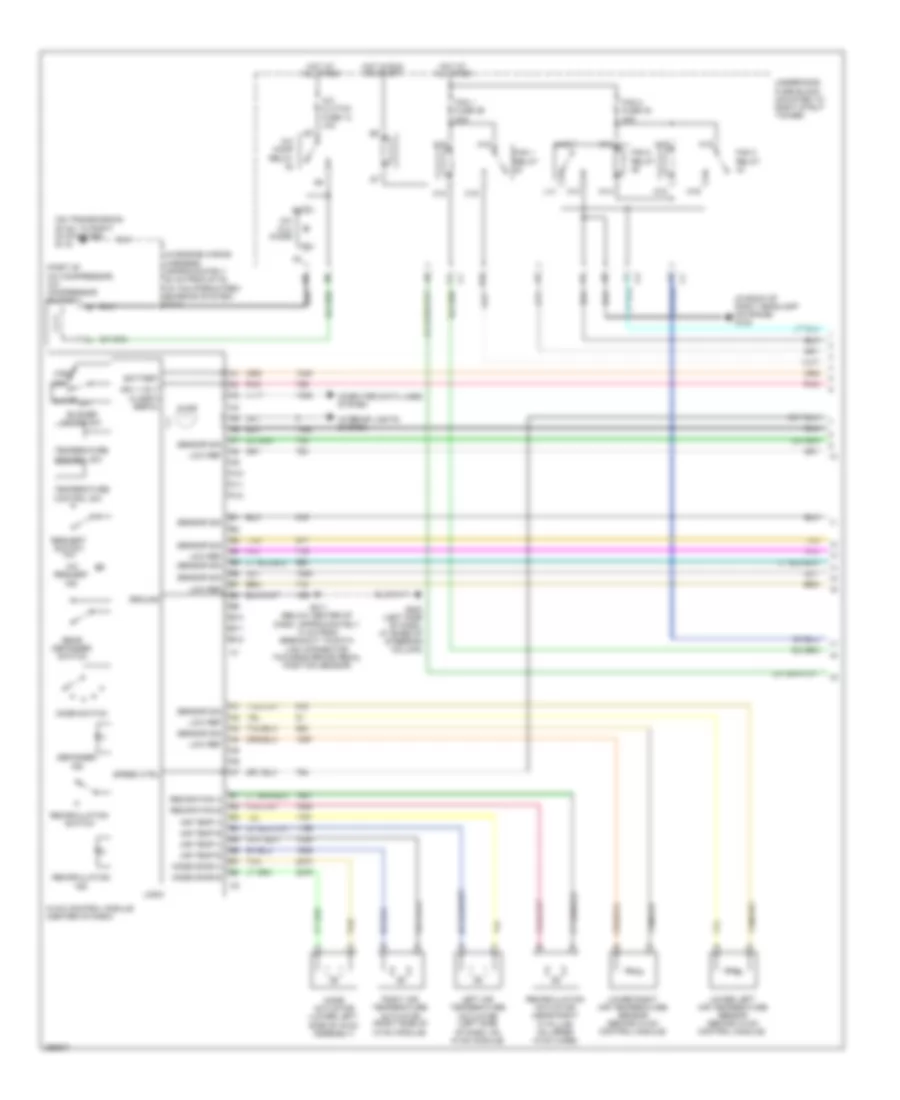
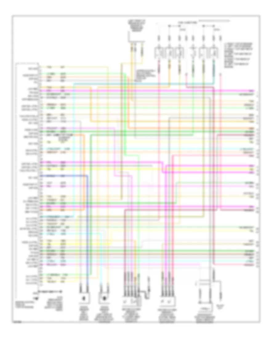
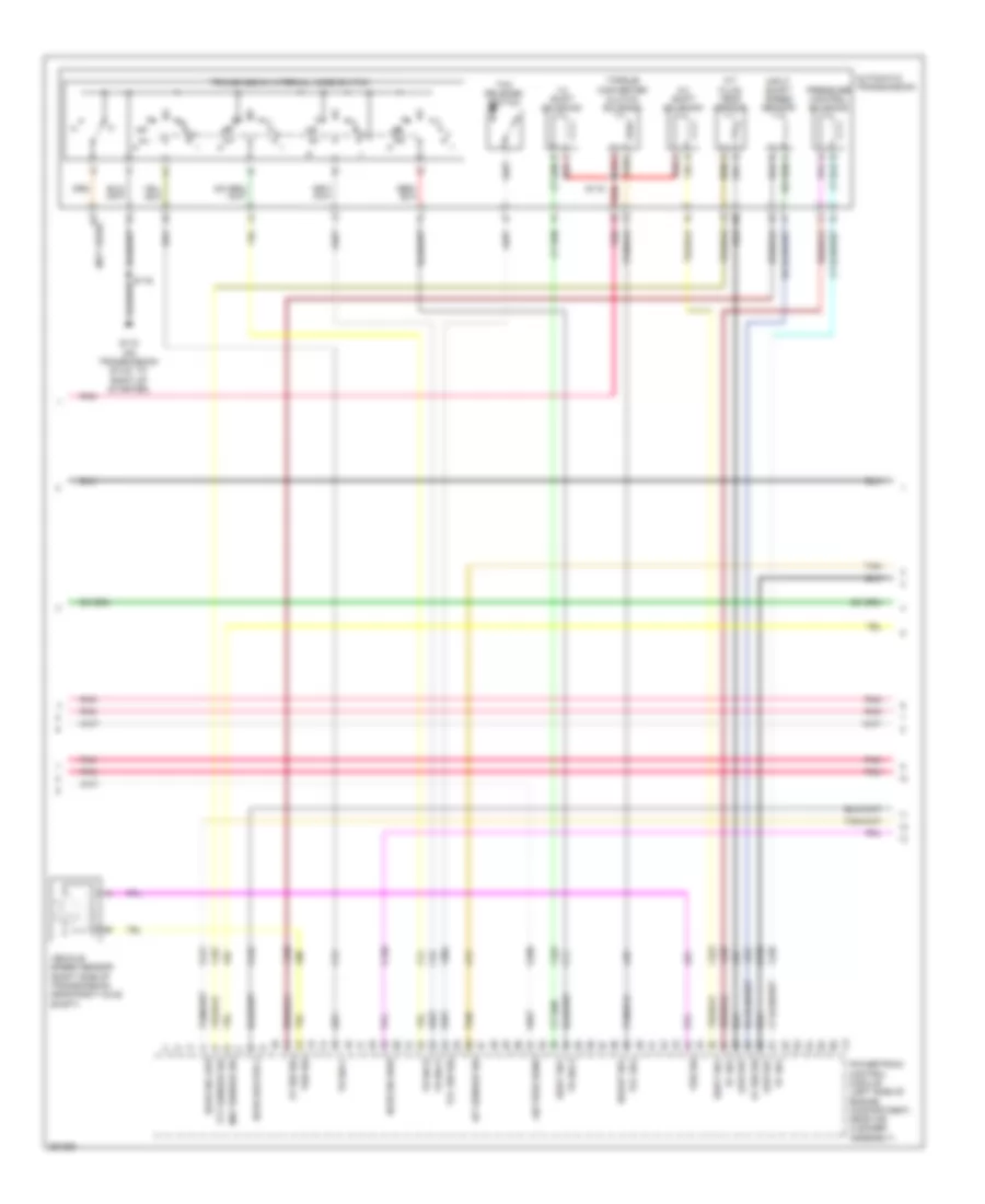
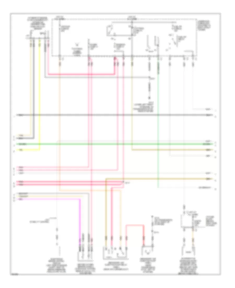
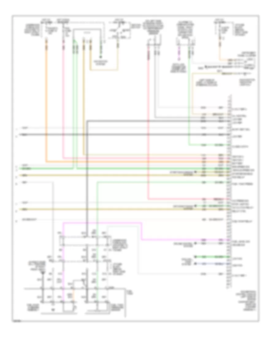
3.6L VIN 7
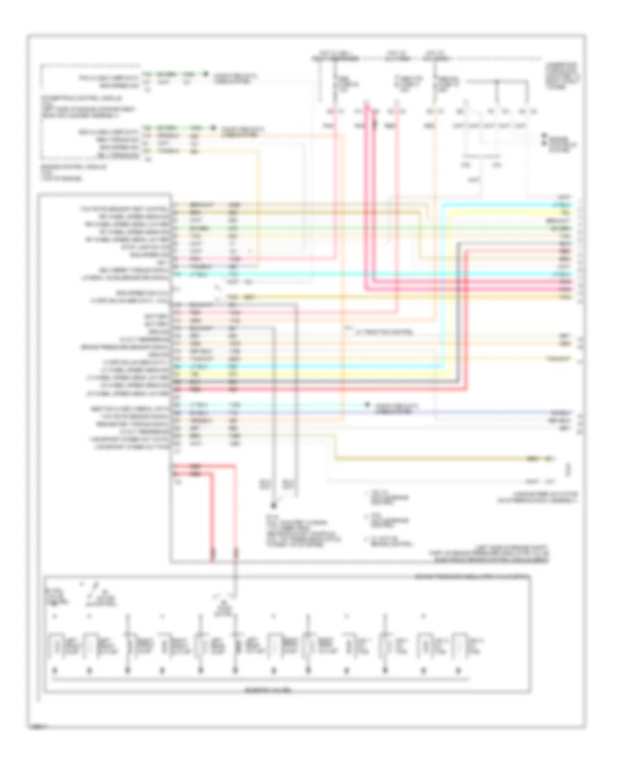
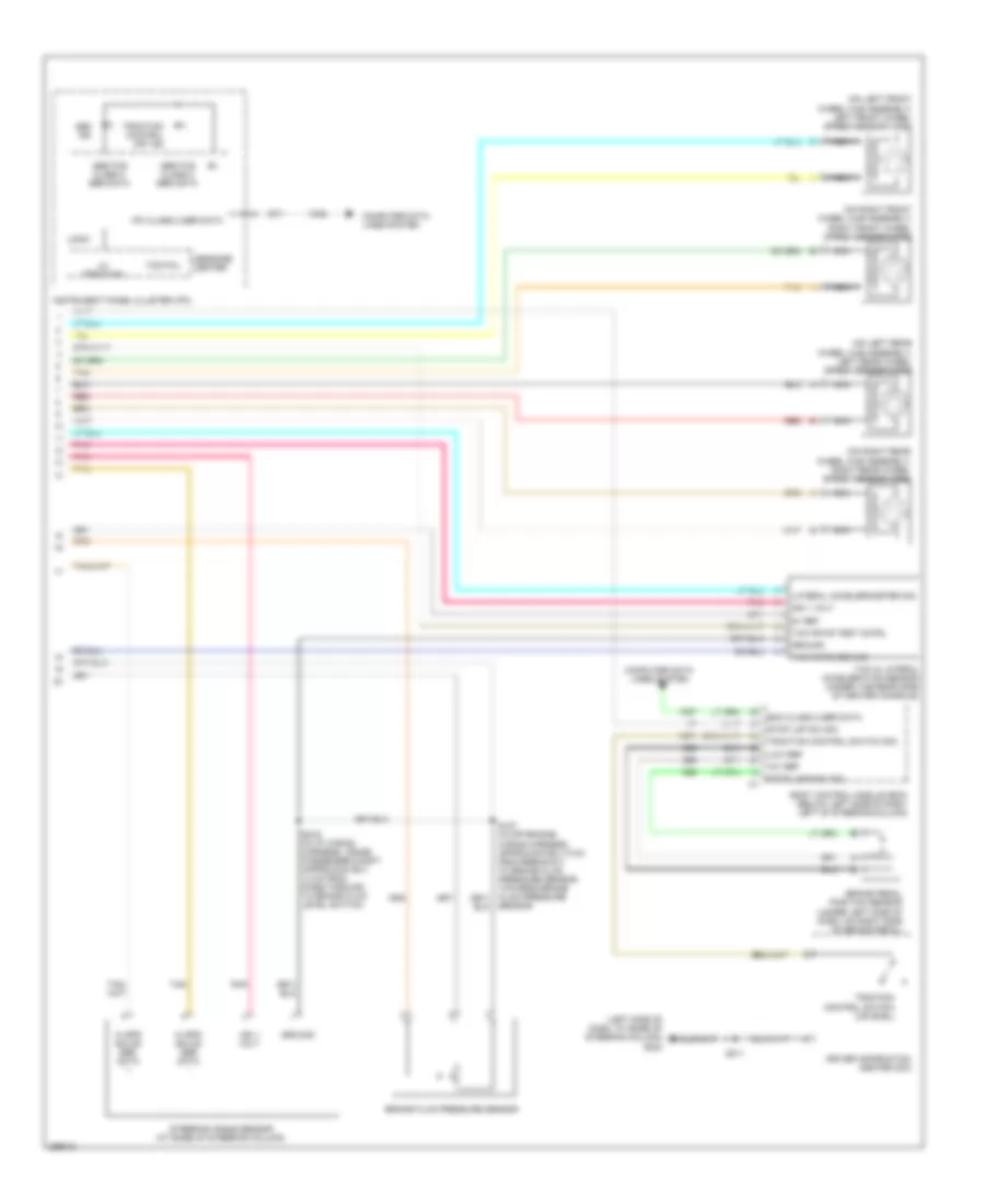
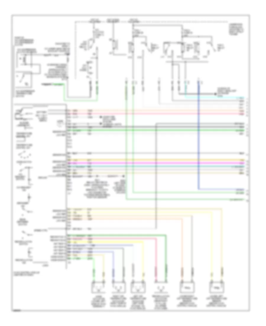
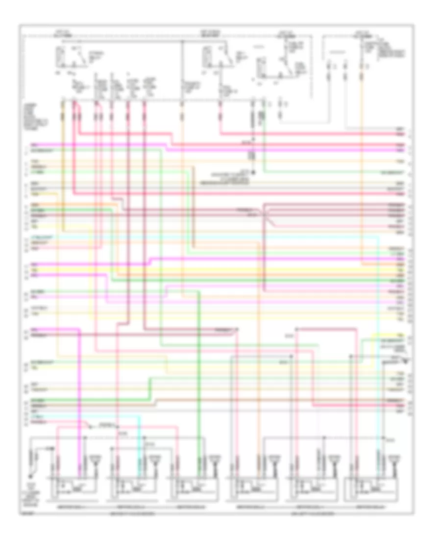
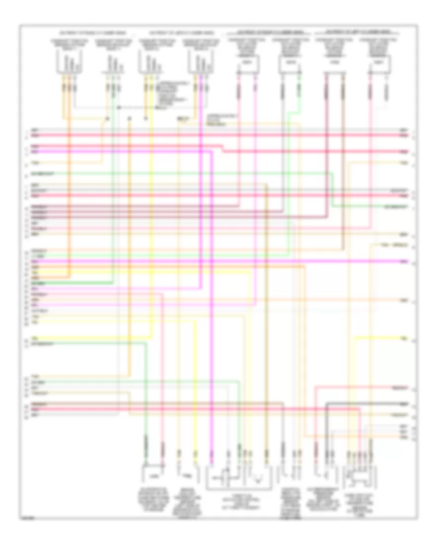
3.6L VIN 7, Электросхема автоматической коробки передач АКПП для Buick Allure CXL 2007
 https://portal-diagnostov.com/license.html
Automotive Electricians Portal FZCO
Automotive Electricians Portal FZCO
https://portal-diagnostov.com/license.html
https://portal-diagnostov.com/license.html
Automotive Electricians Portal FZCO
Automotive Electricians Portal FZCO
3.6L VIN 7, Электросхема автоматической коробки передач АКПП для Buick Allure CXL 2007 - Список элементов:
- (behind left side of dash, left of steering column) body control module
- (behind right side of dash, approximately 4 cm from breakout to rcdlr, towards ambient light sensor)
- 1-2 shift sol valve
- 1-2 sol vlv ctrl
- 10 volt ref
- 2-3 shift sol valve
- 2-3 sol vlv ctrl
- Automatic transaxle fluid temperature sensor
- Automatic transmission
- Battery
- Brake pedal position sensor (under left side of dash, on right side of brake pedal)
- Code a
- Code b
- Code c
- Data link connector (under left side of dash)
- Engine control module (top of engine)
- G115 (mounted to bank 1 cylinder head above exhaust manifold)
- Gmlan serial data
- Ground
- Hot at all times
- Hot in run or start
- Ign 1
- Ign 3 voltage
- Iss high sig
- Iss low sig
- Low ref
- P/n
- P/n signal
- Parity
- Pc sol vlv ctrl
- Pc sol vlv hi ctrl
- Pnk
- Pressure control solenoid valve
- Red
- Red s115
- S116
- S201
- S202
- Serial data bus+
- Serial data bus-
- Stop lp sw
- Stop lp sw sig
- Sw sig
- Tan b
- Tcc pwm sol ctrl
- Tcc rel sw sig
- Tcc release switch
- Tcc sol valve
- Tcm fuse 8 15a
- Terminator resistor
- Tft sens sig
- Trans range a
- Trans range b
- Trans range c
- Trans range p
- Trans sol fuse 21 10a
- Transmission control module (tcm) (inside air cleaner, left front of engine compartment)
- Transmission fluid pressure manual valve position switch
- Transmission input shaft speed sensor
- Transmission internal mode switch
- Underhood fuse block (mounted to right strut c1 tower)
- Vehicle speed sensor (right side of transmission, near right axle shaft)
- Vss hi sig
- Vss low sig
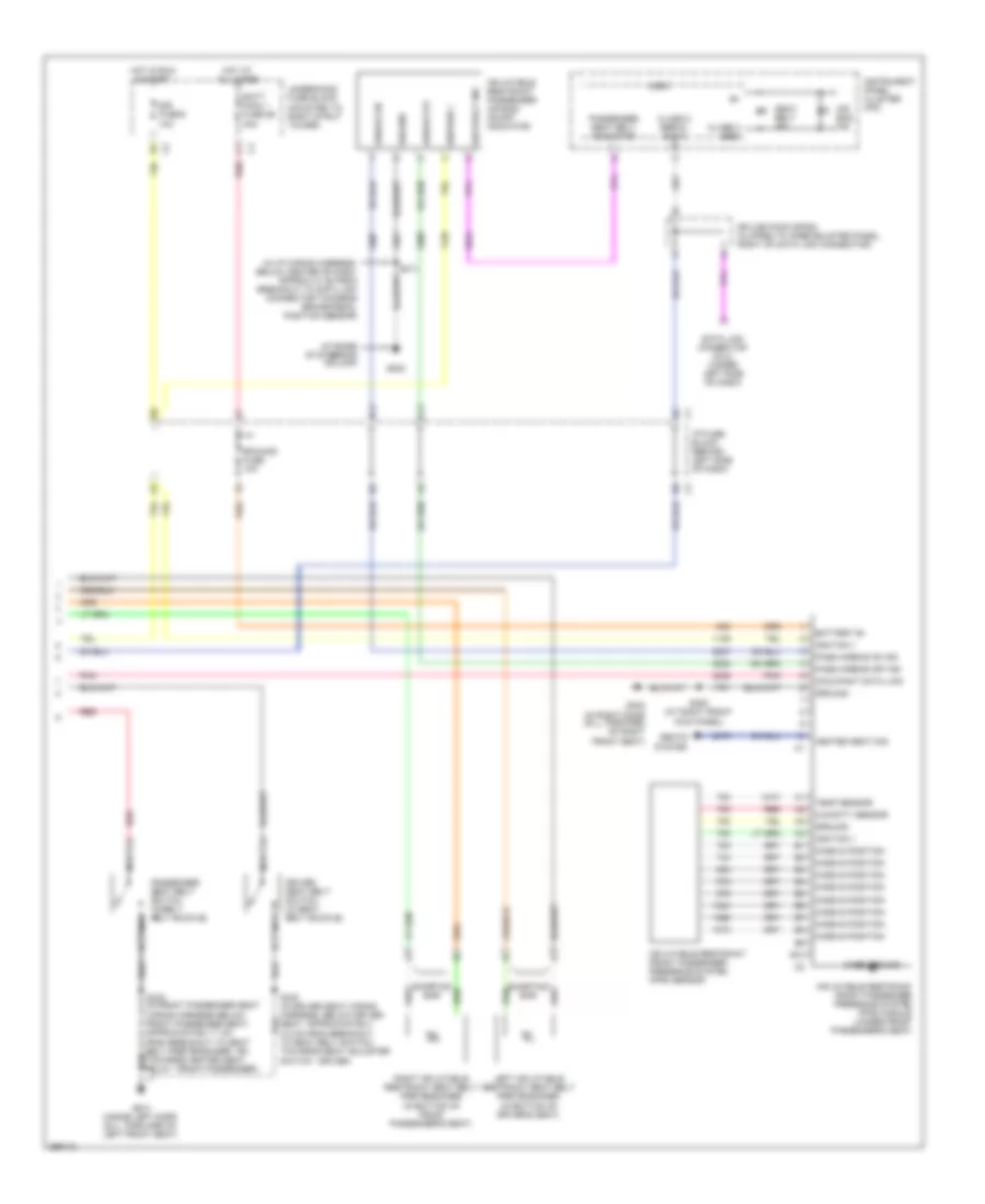
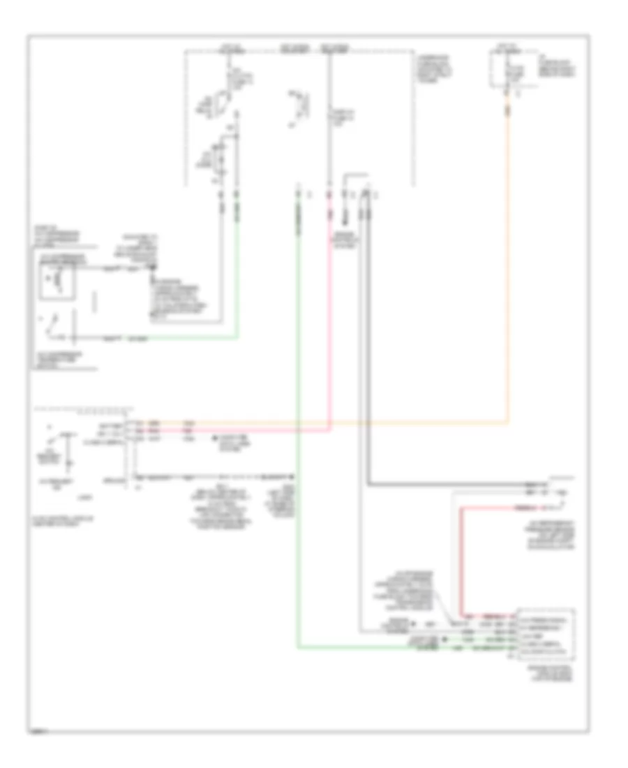
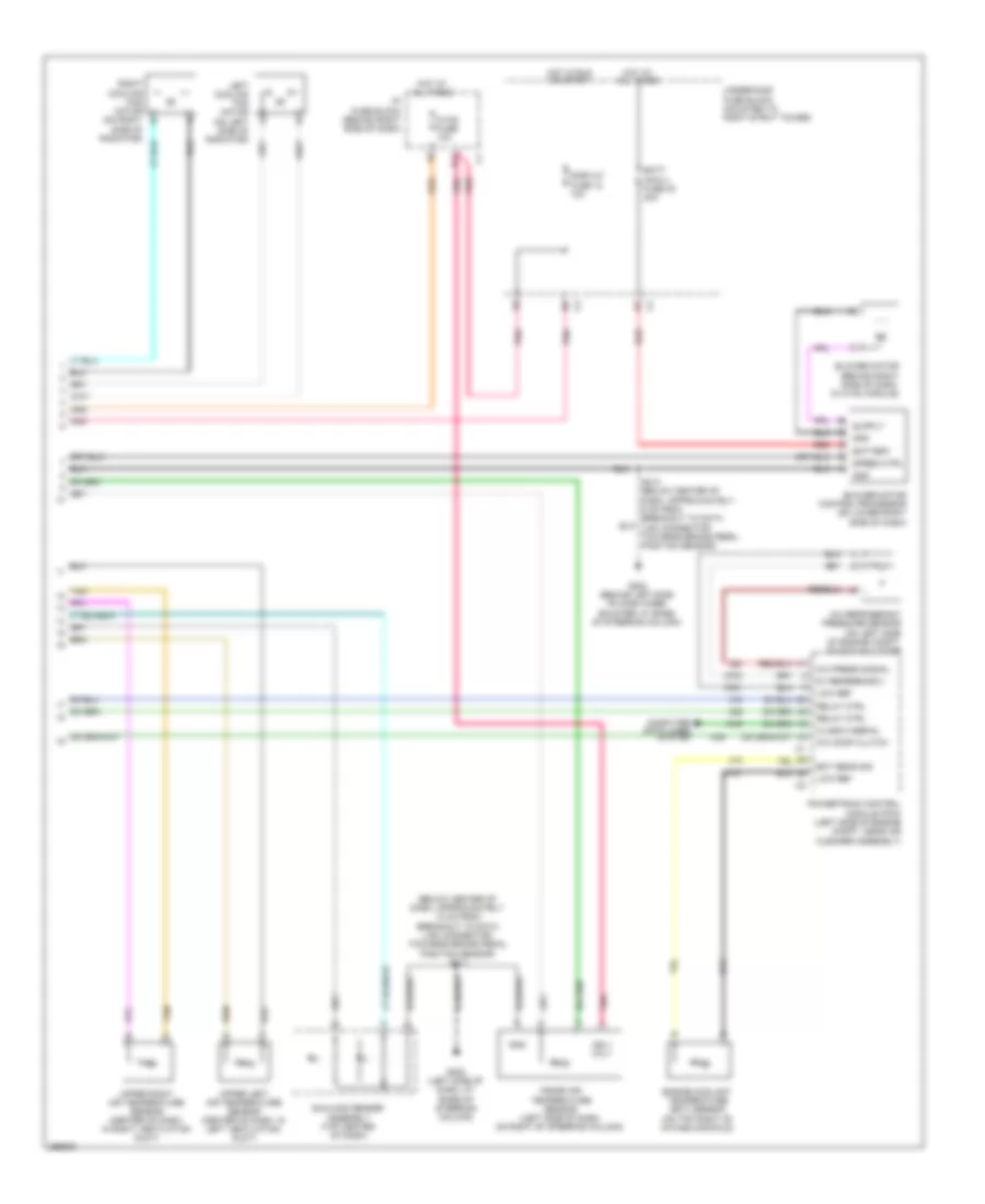
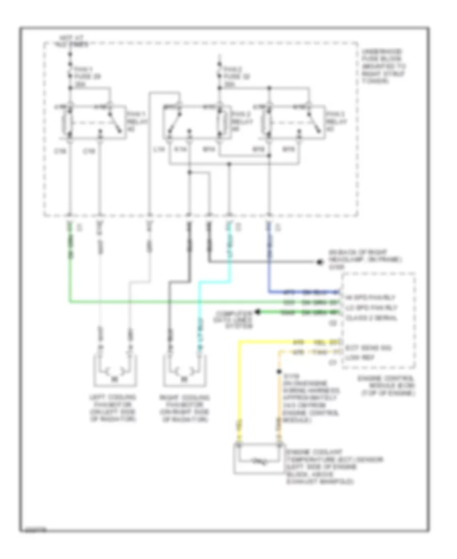
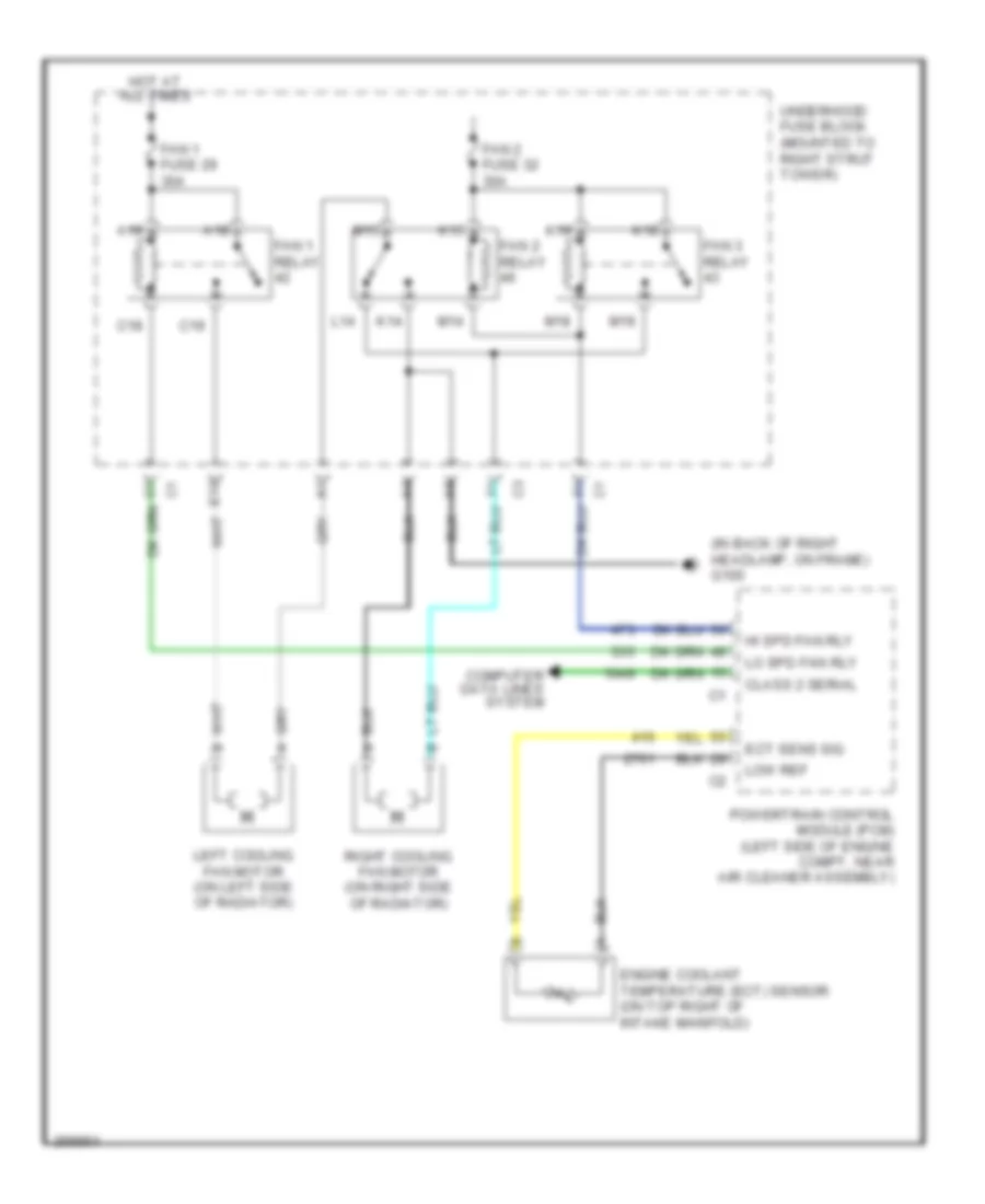
3.8L VIN 2
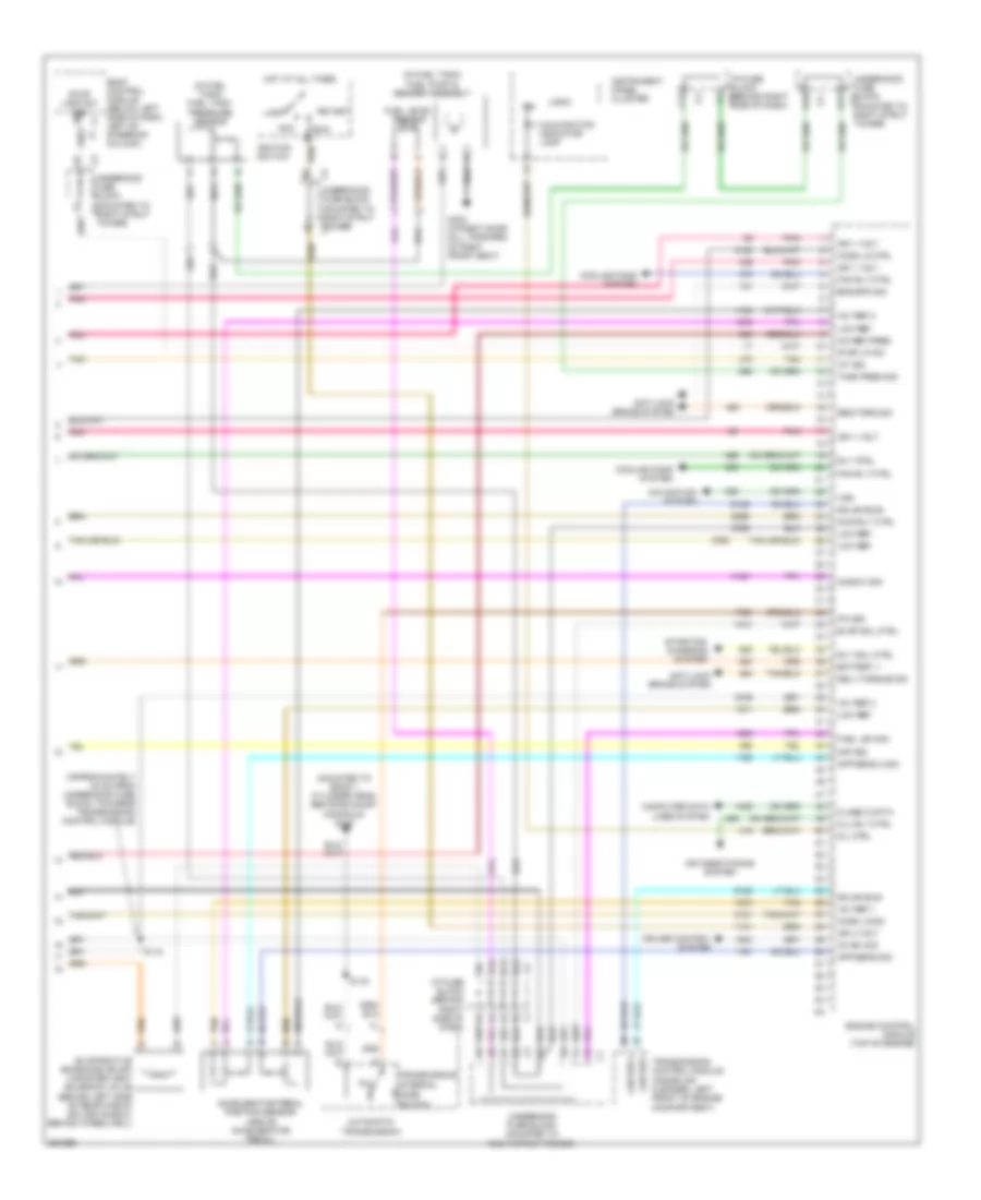
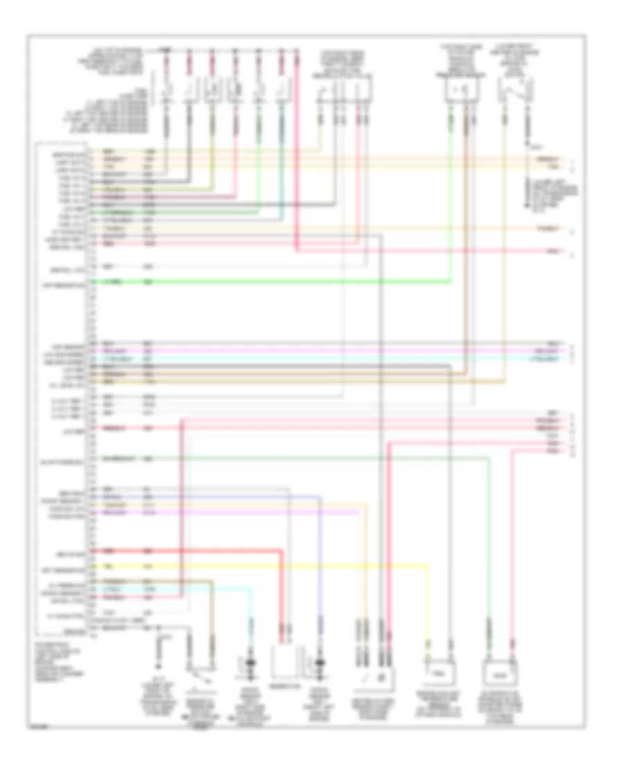
3.8L VIN 2, Электросхема автоматической коробки передач АКПП для Buick Allure CXL 2007
3.8L VIN 2, Электросхема автоматической коробки передач АКПП для Buick Allure CXL 2007 - Список элементов:
- (not used)
- (on top right of intake manifold)
- 1-2 shift sol
- 1-2 shift solenoid valve
- 2-3 shift sol
- 2-3 shift solenoid valve
- 5 volt ref 1
- A/t fluid pressure manual valve position switch
- A/t fluid temp- erature sensor
- Acc
- At iss sig high
- At iss sig low
- Automatic transmission
- Battery
- Code a
- Code b
- Code c
- Ect sensor sig
- Engine coolant temperature sensor
- G113 (lower left front of engine, on transmission stud, near starter)
- Ground
- Hot at all times
- Hot in run or start
- Ignition 1
- Ignition 3
- Ignition switch
- Input shaft speed sensor
- Lock
- Low ref
- Manifold absolute pressure sensor (top right side of intake manifold)
- Map sensor sig
- Parity
- Pc sol high
- Pc sol low
- Pcm fuse 15 10a
- Pcm/ etc fuse 16 15a
- Pnk
- Powertrain control module (left side of engine compartment, near air cleaner assembly)
- Pressure control solenoid valve
- Red
- Red a
- Run
- S101 (in left front of engine compt, approximately 5 cm from break- out to pcm, towards g113)
- S115
- Start
- Tan b
- Tcc sol
- Tcc sw sig
- Tft sensor sig
- Torque converter clutch solenoid valve
- Tr sig a
- Tr sig b
- Tr sig c
- Tr sig p
- Trans sol fuse 21 10a
- Transmission internal mode switch
- Underhood fuse block (mounted to right strut tower)
- Vehicle speed sensor (right side of transmission, near right axle shaft)
- Vss sig high
- Vss sig low
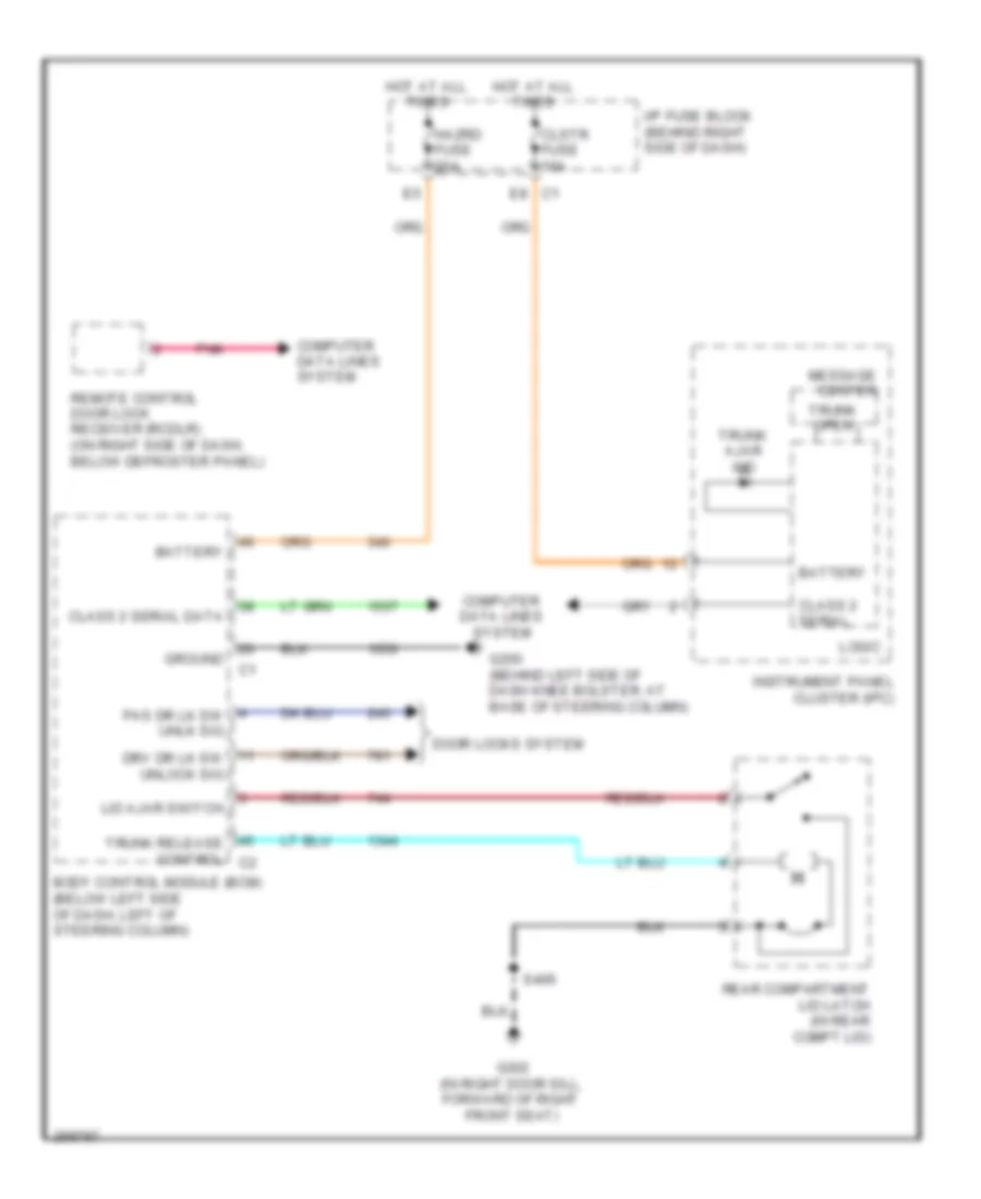
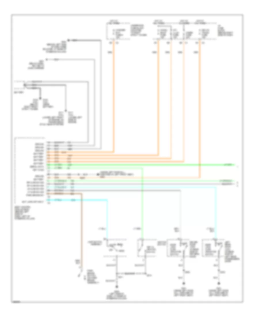
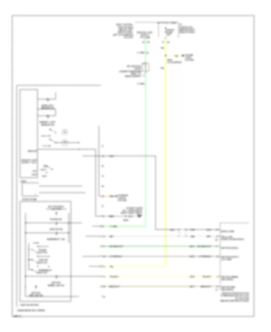
БАГАЖНИК ЗАДНЯЯ ДВЕРЬ ЛЮЧОК ТОПЛИВНОГО БАКА
Электросхема открывания багажника для Buick Allure CXL 2007
Электросхема открывания багажника для Buick Allure CXL 2007 - Список элементов:
- Battery
- Body control module (bcm) (below left side of dash, left of steering column)
- Class 2 serial
- Class 2 serial data
- Clstr fuse 10a
- Computer data lines system
- Door locks system
- Drv dr lk sw unlock sig
- E8 c1
- G200 (behind left side of dash knee bolster, at base of steering column)
- G302 (in right door sill, forward of right front seat)
- Ground
- Hazrd fuse 20a
- Hot at all times
- I/p fuse block (behind right side of dash)
- Instrument panel cluster (ipc)
- Lid ajar switch
- Logic
- Message center
- Pas dr lk sw unlk sig
- Pnk
- Rear compartment lid latch (in rear compt lid)
- Remote control door lock receiver (rcdlr) (on right side of dash, below defroster panel)
- S406
- Trunk ajar ind
- Trunk open
- Trunk release control c2
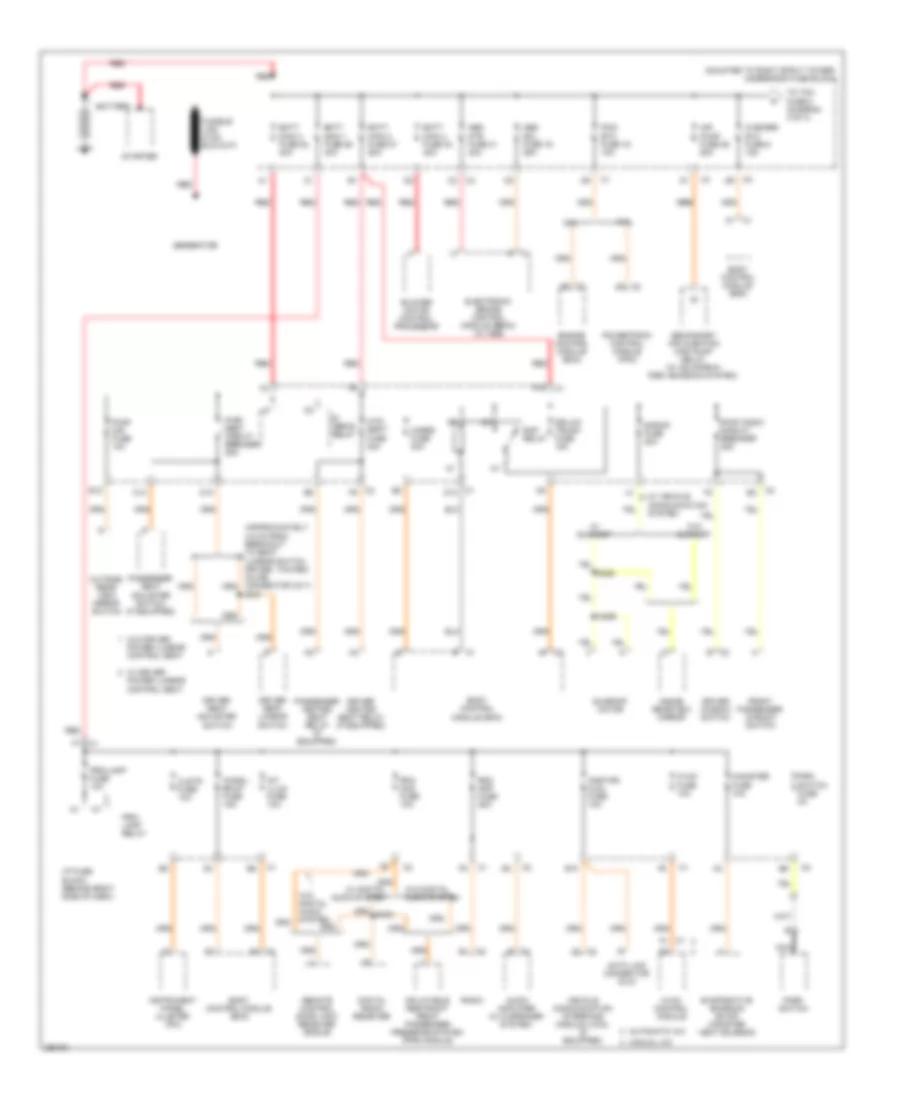
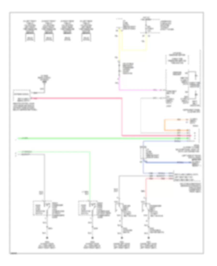
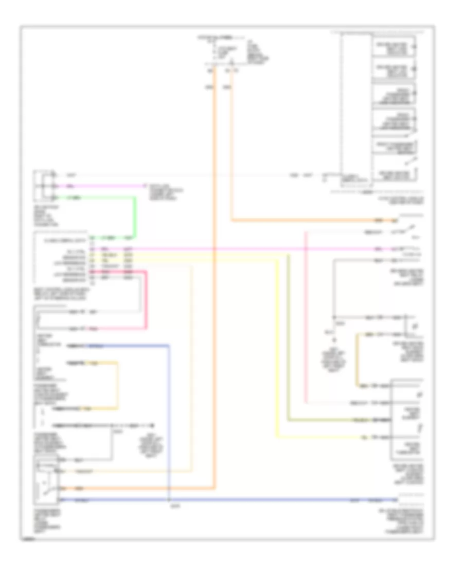
БЛОК ПРЕДОХРАНИТЕЛЕЙ И РЕЛЕ
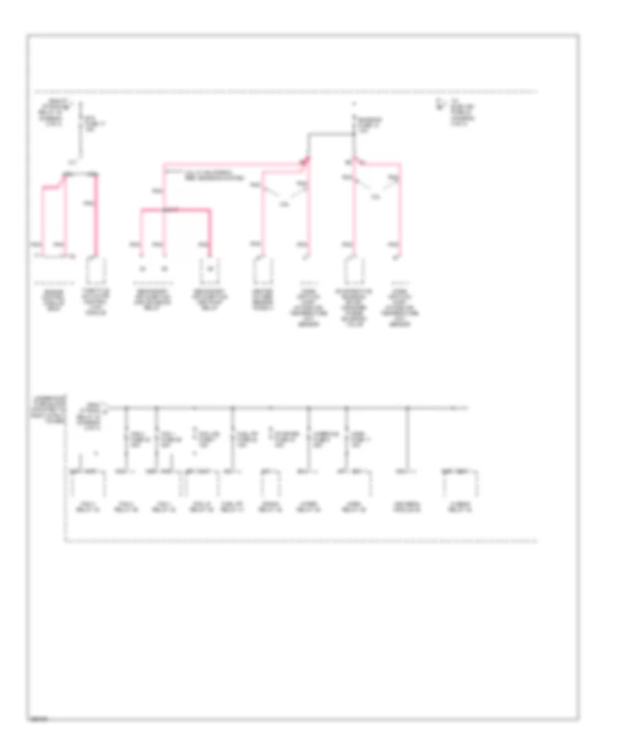
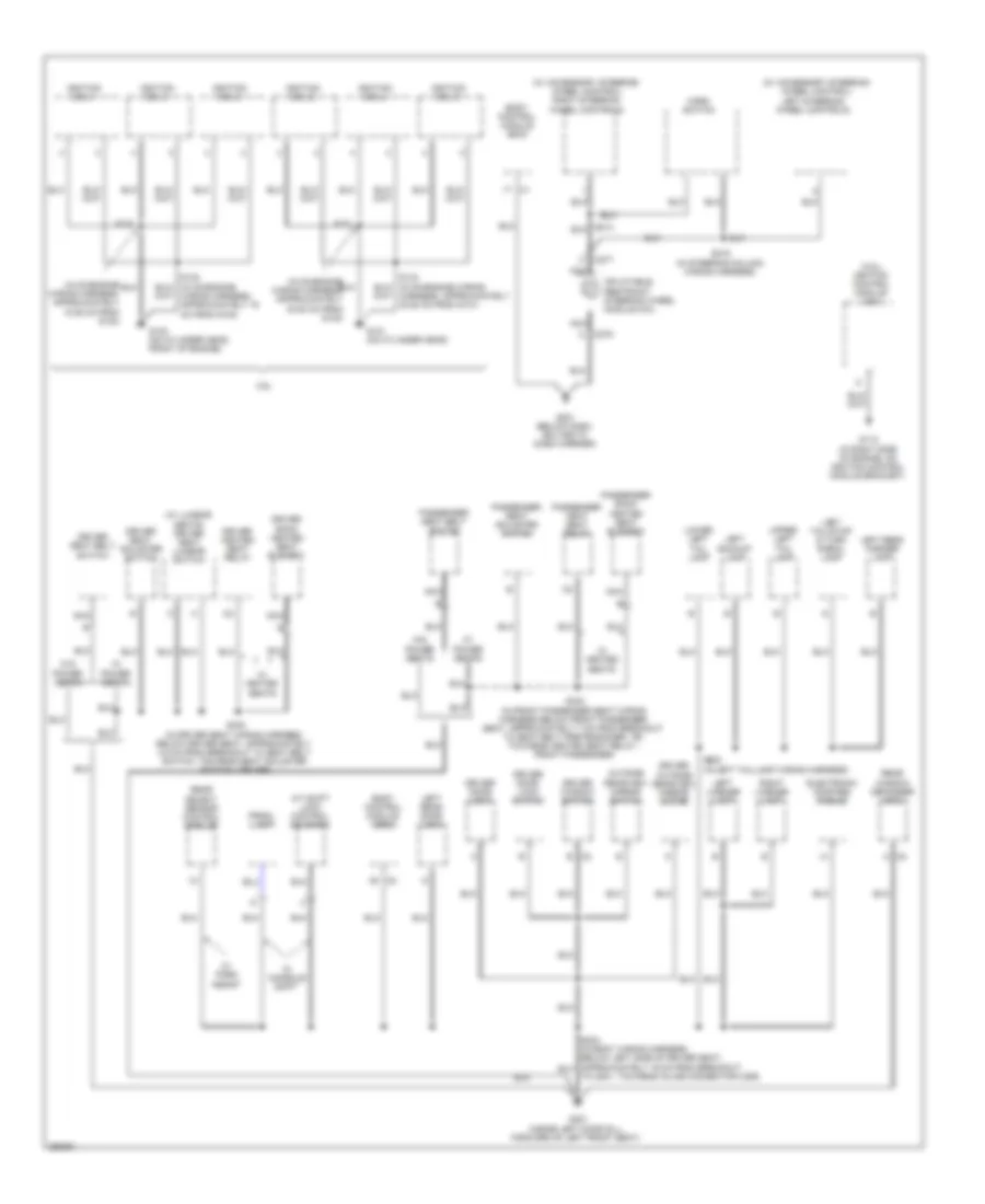
Электросхема блока предохранителей и реле (1 из 4) для Buick Allure CXL 2007
Электросхема блока предохранителей и реле (1 из 4) для Buick Allure CXL 2007 - Список элементов:
- (mounted to right strut tower) underhood fuse block
- 3.6l
- 3.8l
- A1 c1
- Abs mtr fuse 31 40a
- Abs sol fuse 19 25a
- Air pump fuse 25 50a
- Audio amplifier (w/ 9 speaker system)
- Automatic a/c
- B10
- Batt main 1 fuse 26 40a
- Batt main 2 fuse 27 50a
- Batt main 3 fuse 28 40a
- Batt main 4 fuse 30 30a
- Battery
- Blower motor control processor
- Body control module (bcm)
- C1 b1
- C1 d12
- C10
- C2 d9
- C2 e2
- C2 f9
- C4 c2
- Canister fuse 10a
- Chmsl/ bkup fuse 15a
- Clstr fuse 10a
- D10
- Data link connector (dlc)
- Digital radio receiver
- Dr/lck trunk fuse 15a
- Driver heated seat relay (if equipped)
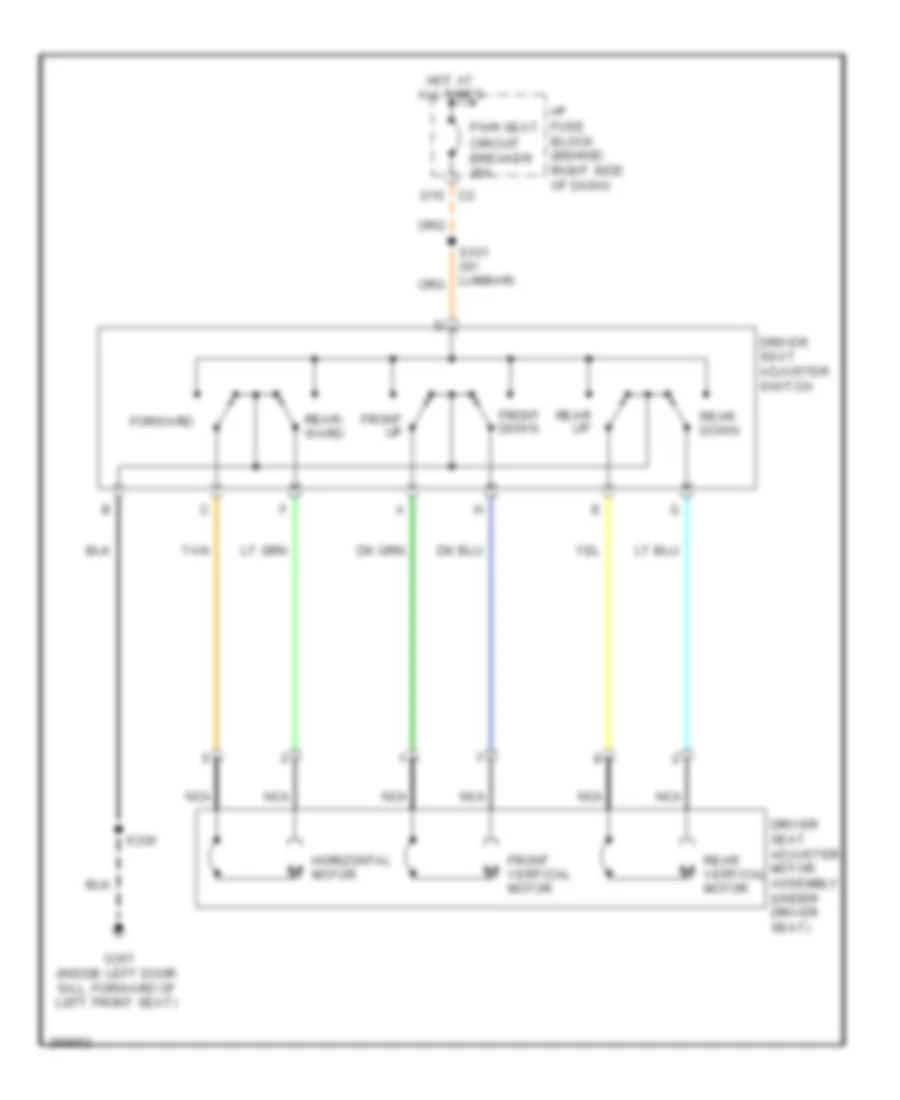
- Driver seat adjuster switch
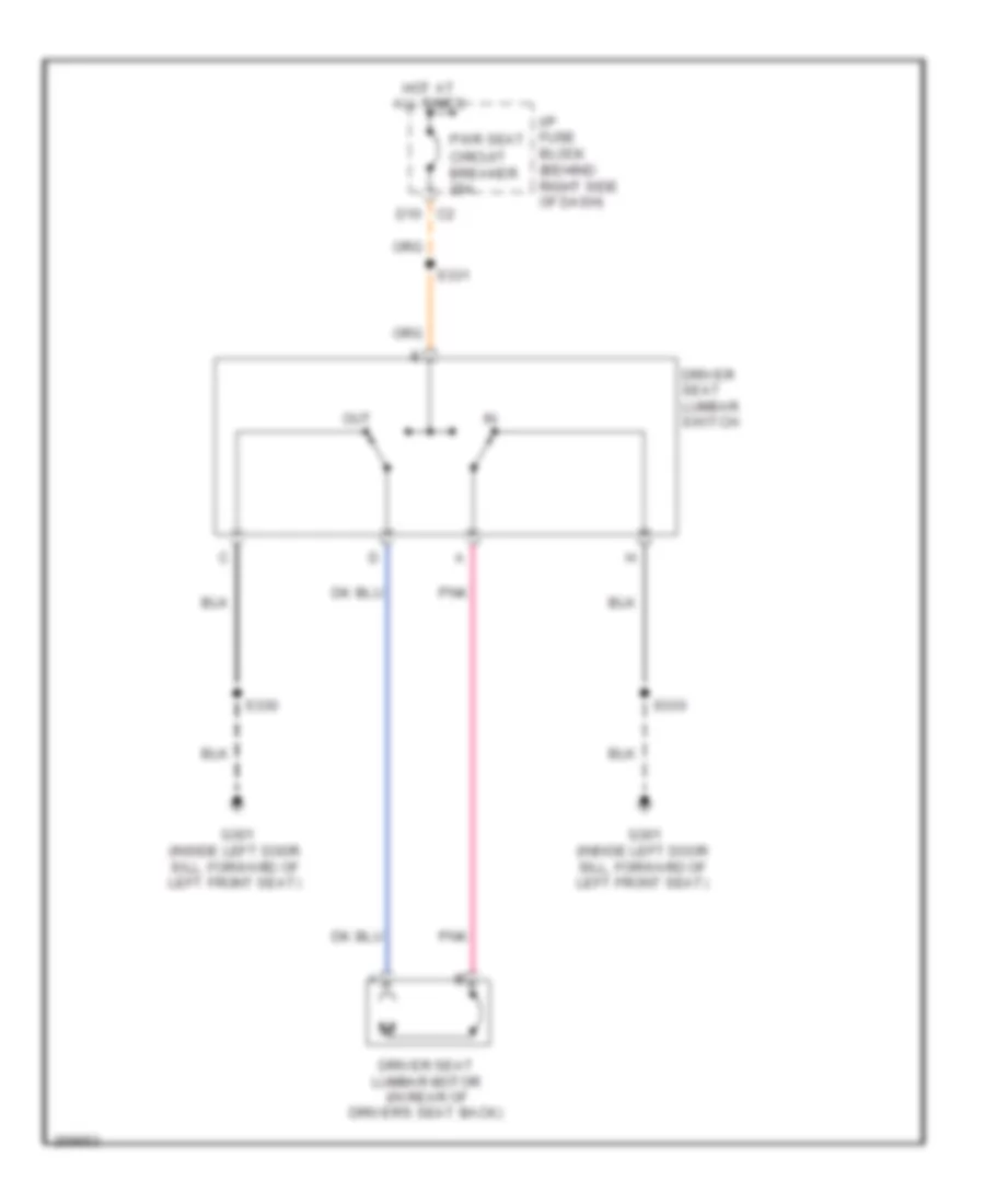
- Driver seat lumbar switch
- Driver window switch
- E c1
- E c2
- E12
- Electronic brake control module (ebcm) (w/ abs)
- Engine control module (ecm)
- Evaporative emission (evap) canister vent solenoid
- F10
- Front passenger window switch
- Generator
- Hazrd fuse 20a
- Htd/ seat fuse 20a
- Hvac control module
- Hvac fuse 10a
- I/p fuse block (behind right side of dash)
- Inflatable restraint front passenger presence system (pps) module
- Inside rearview mirror
- Instrument panel cluster (ipc)
- Int illum fuse 10a
- Manual a/c
- Nca
- Onstar/ aldl fuse 10a
- Outside rear view mirror switch
- Park switch
- Passenger heated seat relay (if equipped)
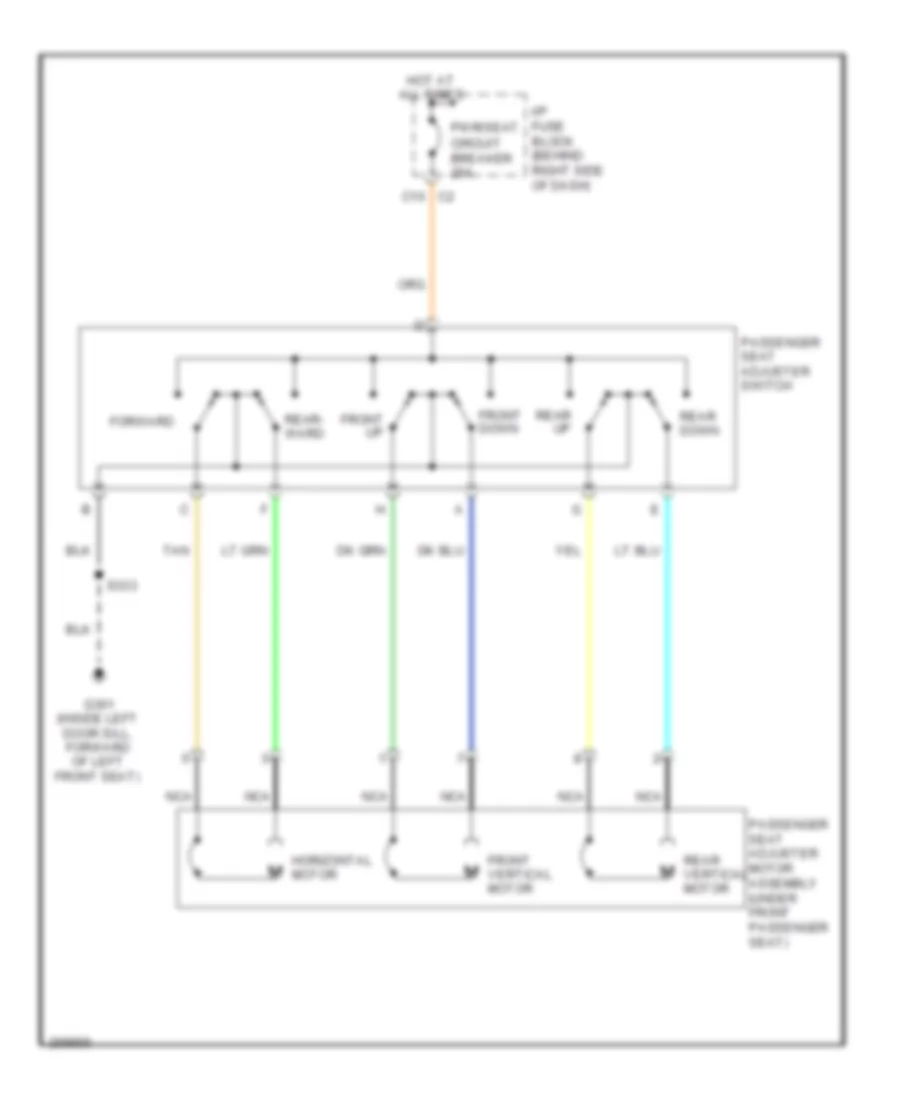
- Passenger seat adjuster switch (if equipped)
- Pcm/ etc fuse 16 15a
- Power lumbar control seat
- Powertrain control module (pcm)
- Prk/ lamp relay
- Prk/ switch fuse 5a
- Prk/lamp fuse 10a
- Pwr wndw circuit breaker 25a
- Pwr/ mir fuse 10a
- Pwr/ seat circuit breaker 25a
- R/ defog relay
- Radio
- Rap relay
- Rdo amp fuse 25a
- Red
- Remote control door lock receiver (rcdlr)
- Rfa/ mod fuse 10a
- S/roof fuse 20a
- S331
- S394
- S395
- Secondary air injection (air) pump relay (w/ california pzev emission system)
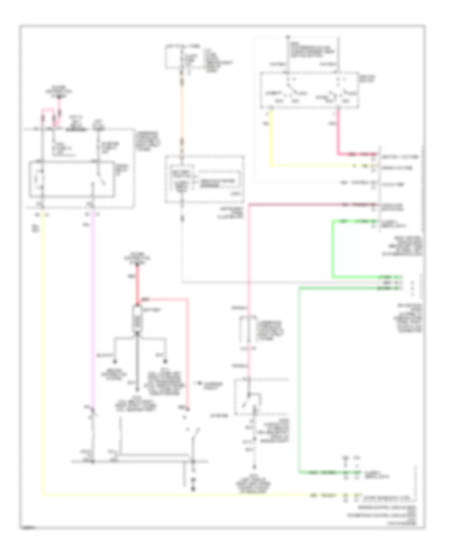
- Starter
- Sunroof motor
- To tcm fuse 8 (diagram 2 of 4)
- Vehicle communication interface module (vcim) (if equipped)
- W/ digital audio system
- W/ driver
- W/ sunroof
- W/ vehicle communication system
- W/o digital audio system
- W/o driver
- W/o sunroof
- Washer/ rvc fuse 6 15a
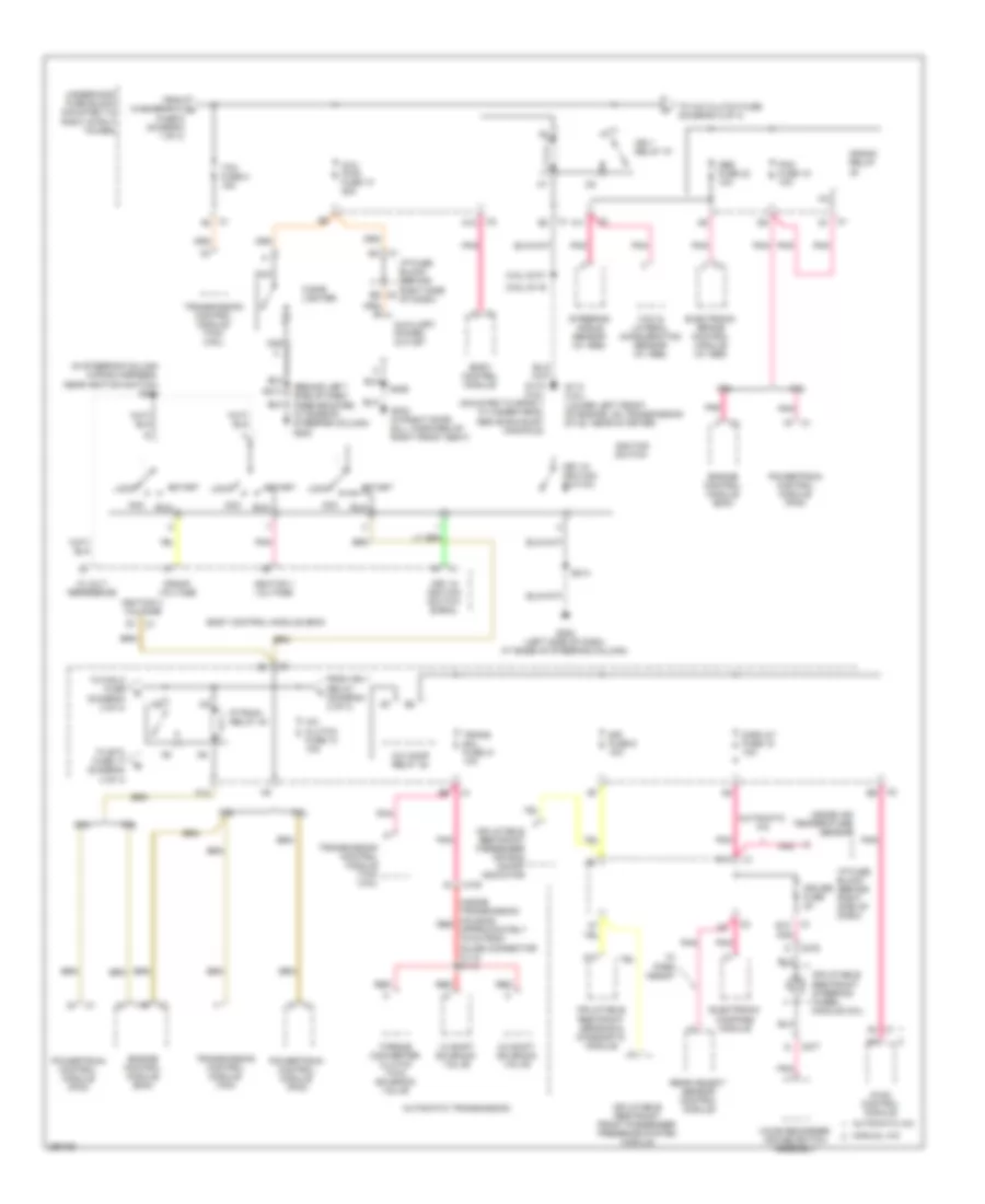
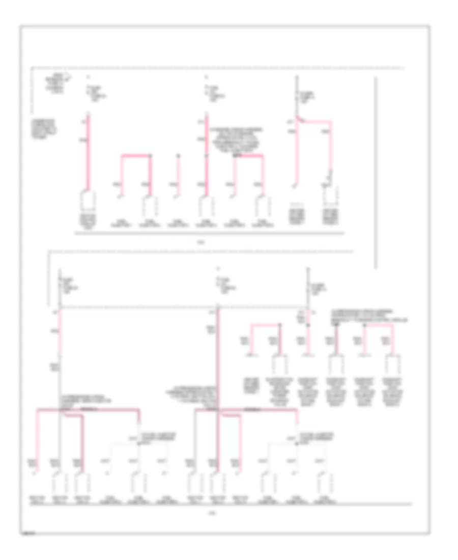
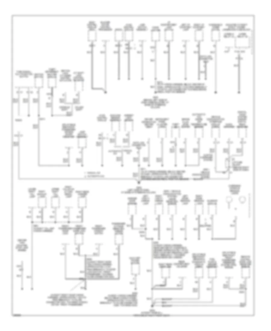
Электросхема блока предохранителей и реле (2 из 4) для Buick Allure CXL 2007
Электросхема блока предохранителей и реле (2 из 4) для Buick Allure CXL 2007 - Список элементов:
- (3.6l) s116
- (3.8l) s101
- (behind left side of dash knee bolster, at base of steering column) g200
- (in steering column wiring harness, near ignition switch) s200
- (inside transmission housing, red approximately 19 cm from inline connector c113) s115
- 1-2 shift solenoid valve
- 12 volt reference
- 2-3 shift solenoid valve
- 3.6l
- 3.8l
- A/c clutch fuse 13 10a
- A/c comp relay 38
- A10
- A11
- A2 c1
- Abs fuse 23 10a
- Acc
- Automatic a/c
- Automatic transmission
- Aux pwr fuse 10 25a
- Auxiliary power outlet
- Body control module
- Body control module (bcm)
- C1 a5
- C1 b3
- C1 b4
- C1 d1
- C100
- C2 a12
- C2 b9
- C275
- C277
- Cigar lighter
- Crank relay
- Crank voltage
- Cruise fuse 2a
- D11
- Display fuse 18 10a
- E12
- Electronic brake control module (w/ abs)
- Electronic compass module
- Engine control module (ecm)
- F12
- From ign 1 relay (diagram 2 of 4)
- From washer/rvc a fuse 6 (diagram 1 of 4)
- G113 (3.8l) (lower left front of engine, on transmission stud, near starter)
- G115 (3.6l) (mounted to bank 1 cylinder head, above exhaust manifold)
- G202 (left side of dash, at base of steering column)
- G302 (in right door sill, forward of right front seat)
- Hvac control module
- I/p fuse block (behind right side of dash)
- Ign 1 relay 37
- Ignition 1 voltage
- Ignition 3 voltage
- Ignition switch
- Inflatable restraint front passenger presence system module
- Inflatable restraint passenger air bag on/off indicator
- Inflatable restraint sensing & diagnostic module
- Inflatable restraint steering wheel module coil
- Inside air temperature sensor
- Key in ignition switch
- Key in ignition switch signal
- Lock
- Manual a/c
- Nca
- P/train relay 40
- Pcm fuse 15 10a
- Pnk
- Powertrain control module (pcm)
- Rear object sensor control module
- Red
- Run
- S213
- S214
- S406
- Sir fuse 9 10a
- Start
- Steering angle sensor (w/ abs)
- Tcm fuse 8 15a
- To a/c clutch fuse (diagram 2 of 4)
- To etc fuse 17 (diagram 3 of 4)
- To fan 2 fuse (diagram 3 of 4)
- Torque converter clutch (tcc) solenoid valve
- Trans sol fuse 21 10a
- Transmission control module (tcm)
- Transmission control module (tcm) (3.6l)
- Underhood fuse block (mounted to right strut tower)
- Voice recorder/ cruise switch assembly
- W/ park assist
- Yaw & lateral acceleration sensor (w/ abs)
Электросхема блока предохранителей и реле (3 из 4) для Buick Allure CXL 2007
Электросхема блока предохранителей и реле (3 из 4) для Buick Allure CXL 2007 - Список элементов:
- 3.6l
- 3.8l
- 3.8l w/ california pzev emission system
- A12
- A18
- A19
- C10
- C11
- Crank relay 48
- E14
- Emission fuse 12 10a
- Engine control module (ecm)
- Etc fuse 17 15a
- Evaporative emission (evap) canister purge solenoid valve
- Fan 1 fuse 29 30a
- Fan 1 relay 42
- Fan 2 fuse 32 30a
- Fan 2 relay 46
- Fan 3 relay 43
- Fog lp relay 36
- Fog lps fuse 7 15a
- From p/train b relay 40 (diagram 2 of 4)
- From p/train d relay 40 (diagram 2 of 4)
- Fuel pp fuse 22 15a
- Fuel pp relay 41
- G19
- G20
- Hdm beam module 35
- Heated oxygen sensor (ho2s) 2
- Hi beam relay 34
- Horn fuse 11 15a
- Horn relay 39
- K15
- K18
- K19
- Mass air flow (maf)/ intake air temperature (iat) sensor
- Pnk
- S117
- Secondary air injection (air) pump relay
- Secondary air injection (air) solenoid relay
- Starter fuse 33 40a
- Throttle actuator control (tac) module
- To elek ign fuse 24 (diagram 4 of 4)
- Underhood fuse block (mounted to right strut tower)
- Wiper relay 45
- Wiper/ws fuse 5 25a
Электросхема блока предохранителей и реле (4 из 4) для Buick Allure CXL 2007
Электросхема блока предохранителей и реле (4 из 4) для Buick Allure CXL 2007 - Список элементов:
- (in engine wiring harness, on top of engine, approximately 8 cm from breakout to fuel injector 3, towards fuel injector 5) s109
- (in fuel injector wiring harness) s104
- (in fuel injector wiring harness) s108
- (in pre-engine wiring harness approximately 5 cm from ignition coil 1 towards ignition coil 3) s106
- (in pre-engine wiring harness, approximately 5.5 cm from breakout to engine control module) s110
- (in pre-engine wiring harness, near injector coils) s103
- 02 ssr fuse 14 15a
- 3.6l
- 3.8l
- A11
- Camshaft position (cmp) actuator solenoid exhaust bank 1
- Camshaft position (cmp) actuator solenoid exhaust bank 2
- Camshaft position (cmp) actuator solenoid intake bank 1
- Camshaft position (cmp) actuator solenoid intake bank 2
- D11
- Elek ign fuse 24 15a
- Evaporative emissions (evap) canister purge solenoid valve
- From emission e fuse 12 (diagram 3 of 4)
- Fuel inj fuse 20 15a
- Fuel injector 1
- Fuel injector 2
- Fuel injector 3
- Fuel injector 4
- Fuel injector 5
- Fuel injector 6
- Heated oxygen sensor (ho2s) 1
- Heated oxygen sensor (ho2s) 2
- Ignition coil 1
- Ignition coil 2
- Ignition coil 3
- Ignition coil 4
- Ignition coil 5
- Ignition coil 6
- Ignition control module (icm)
- Nca
- Pnk
- Underhood fuse block (mounted to right strut tower)
БЛОКИ УПРАВЛЕНИЯ КУЗОВОМ
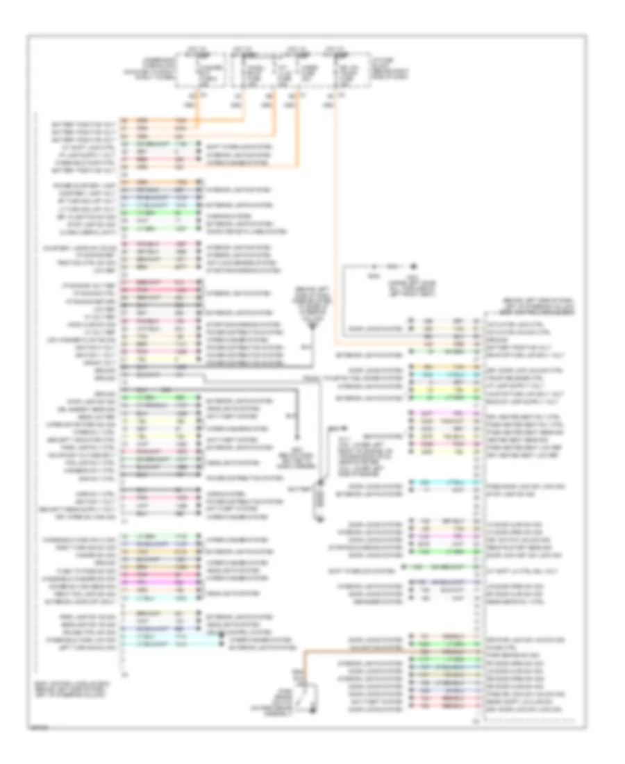
Электросхема блоков управления кузовом для Buick Allure CXL 2007
Электросхема блоков управления кузовом для Buick Allure CXL 2007 - Список элементов:
- (3.6l: lower left front of engine, on transmission stud, near starter) (3.8l: lower left side of engine)
- (behind left side of dash knee bolster, at base of steering column) g200
- (behind left side of dash, left of steering column) body control module (bcm)
- 10 volt ref
- 12 volt ref
- A/t shft lk ctrl sol volt
- A/t shift lock ctrl
- Actuator lock ctrl
- Actuator unlock ctrl
- Anti-lock brakes system
- Anti-theft system
- Battery
- Battery positive volt
- Body control module (bcm) (behind left side of dash, left of steering column)
- C1 e5
- C2 a5
- C2 d9
- Chime ctrl
- Chmsl/ bkup fuse 15a
- Class 2 serial data
- Computer data lines system
- Courtesy lamp volt
- Courtesy lamps sw on sig
- Crank volt
- Cruise control system
- Cruise ctrl sw sig
- Defogger system
- Dimmer sw high beam sig
- Door lock key sw lock sig
- Door locks system
- Dr lck/ trunk fuse 15a
- Drl ambient sens sig
- Drv door lock sw lock sig
- Drv door lock unlock ctrl
- Drv heated seat low ref
- Drv heated seat rly ctrl
- Drvr dr lock sw unlock sig
- Exterior lamps off input
- Exterior lights system
- Flash to pass sw sig
- Fog lamp rly ctrl
- Front fog lamp sw sig
- Frt wiper sw high sig
- G111
- G201 (below dash, bolted to dash carrier)
- G301 (inside left door sill, forward of left front seat)
- Ground
- Hazard sw sig
- Hazrd fuse 20a
- Hdlmp mod voltage sply
- Headlamp sw on sig
- Headlights system
- Heated seat sens sig
- Highbeam rly ctrl
- Hood ajar sw sig
- Horn rly ctrl
- Horns system
- Hot at all times
- I/p dimming ctrl
- I/p dimming ret
- I/p dimming return
- I/p dimming volt ref
- I/p fuse block (behind right side of dash)
- Ignition 1 volt
- Ignition 3 volt
- Int/ illum fuse 10a
- Interior lights system
- Key in ignition sw sig
- Key switch unlock sig
- Left turn sig sw sig
- Lf door ajar sw sig
- Lf door open sw sig
- Lf turn sig lmp volt
- Low ref
- Low washer fluid ind sig
- Lr door ajar sw sig
- Lr door open sw sig
- Lr stop/turn lmp sply volt
- Navigation system
- Park brake sw sig
- Park brake switch (on park brake assembly)
- Park lamp rly ctrl
- Park lamp sw on sig
- Pass door lock sw lock sig
- Pass dr lock sw unlock sig
- Pass heated seat low ref
- Pass heated seat rly ctrl
- Pass heated seat sens sig
- Pnk
- Power courtesy lamp
- Power distribution system
- Rap rly ctrl
- Rear compt lid ajar sw
- Rear defog rly ctrl
- Red
- Remote start sens sig
- Rf door ajar sw sig
- Rf door open sw sig
- Rf turn sig lmp volt
- Right turn sig sw sig
- Rr door ajar sw sig
- Rr door open sw sig
- Rr stop/turn lmp sply volt
- S303
- Seats system
- Security indicator ctrl
- Sens low ref
- Shift interlock system
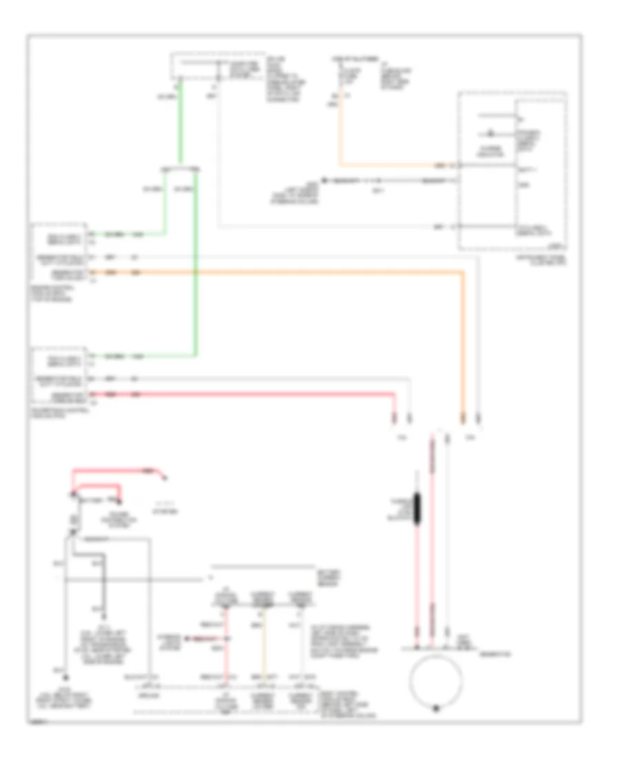
- Starting/charging system
- Stop lamp sw sig
- Tan
- Traction ctrl sw sig
- Trunk release ctrl
- Trunk, tailgate, fuel doors system
- Underhood fuse block (mounted to right strut tower)
- Warning system
- Washer/ rvc fuse 6 15a
- Windshield pump ctrl
- Windshield wash low sig
- Windshield wash sw hi sig
- Windshield washer sw sig
- Wiper motor park sw sig
- Wiper rly ctrl
- Wiper/washer system
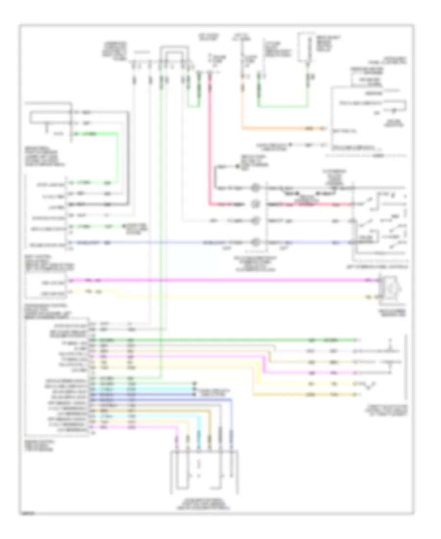
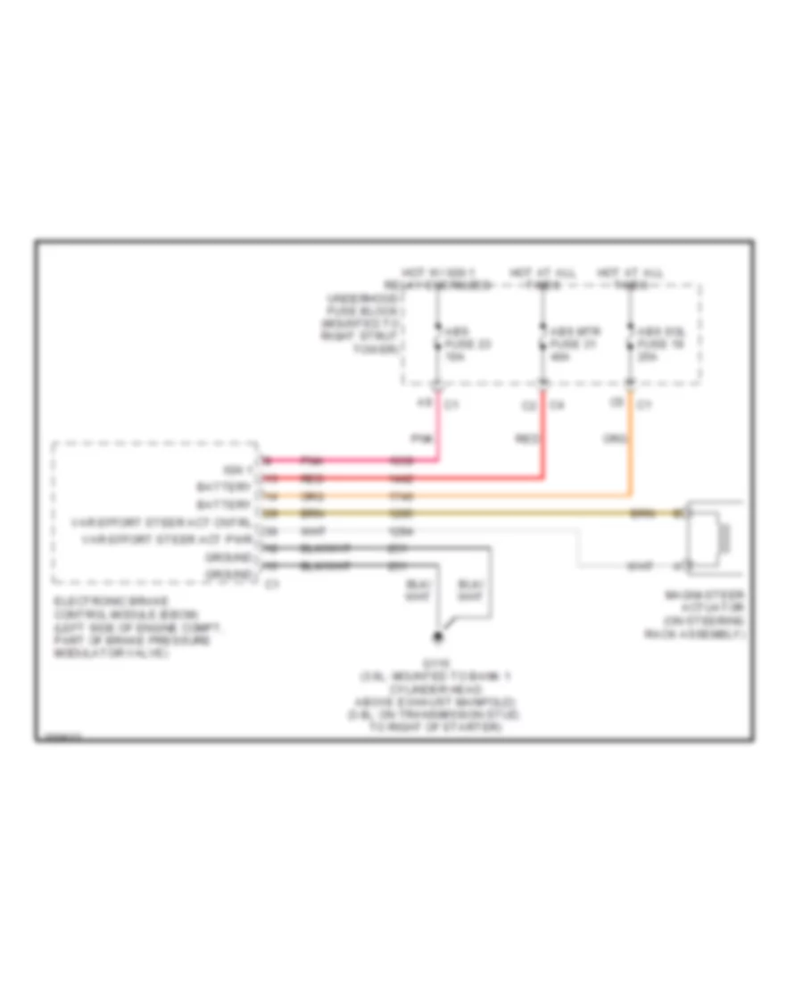
БЛОКИРОВКИ СЕЛЕКТОРА СТОЯНОЧНЫЙ ТОРМОЗ
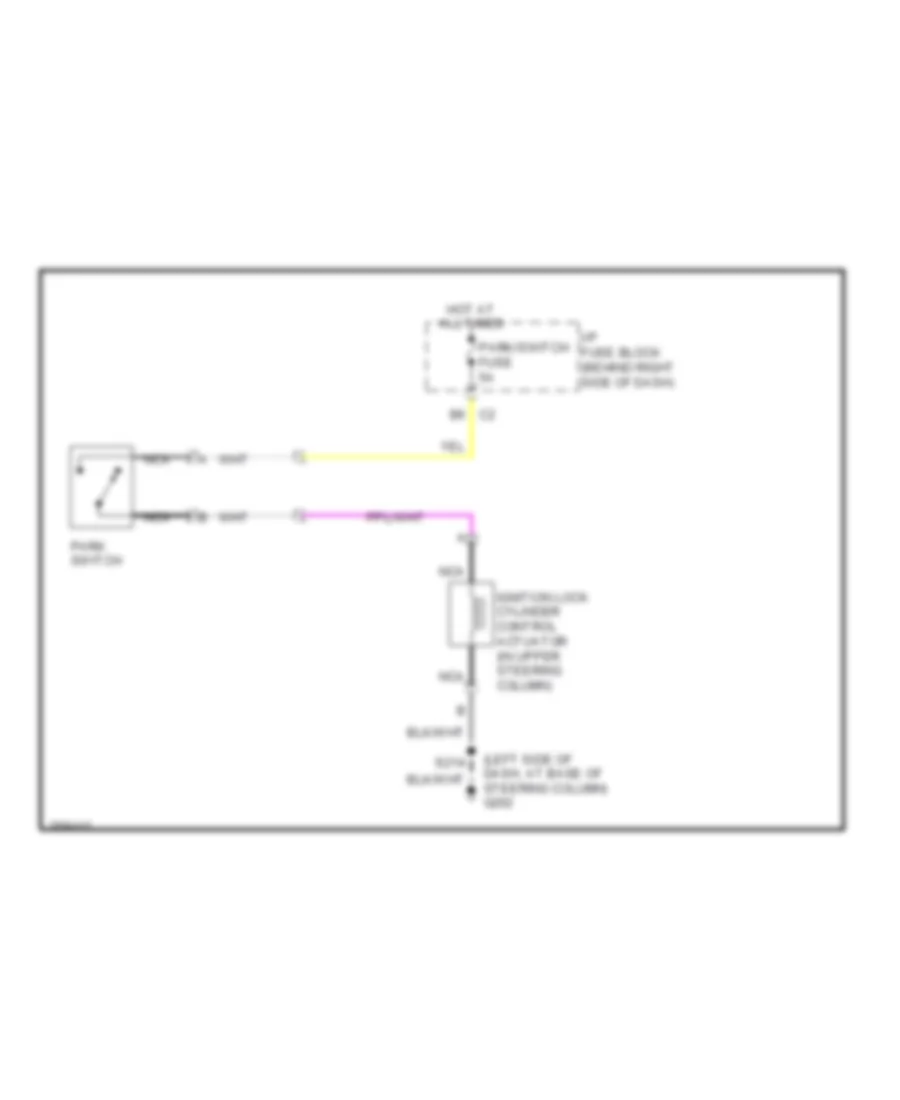
Электросхема соленоида блокировки замка зажигания, С утешьте изменение для Buick Allure CXL 2007
Электросхема соленоида блокировки замка зажигания, С утешьте изменение для Buick Allure CXL 2007 - Список элементов:
- (left side of dash, at base of steering column) g202
- Hot at all times
- I/p fuse block (behind right side of dash)
- Ignition lock cylinder control actuator (in upper steering column)
- Nca
- Park switch
- Park/switch fuse 5a
- S214
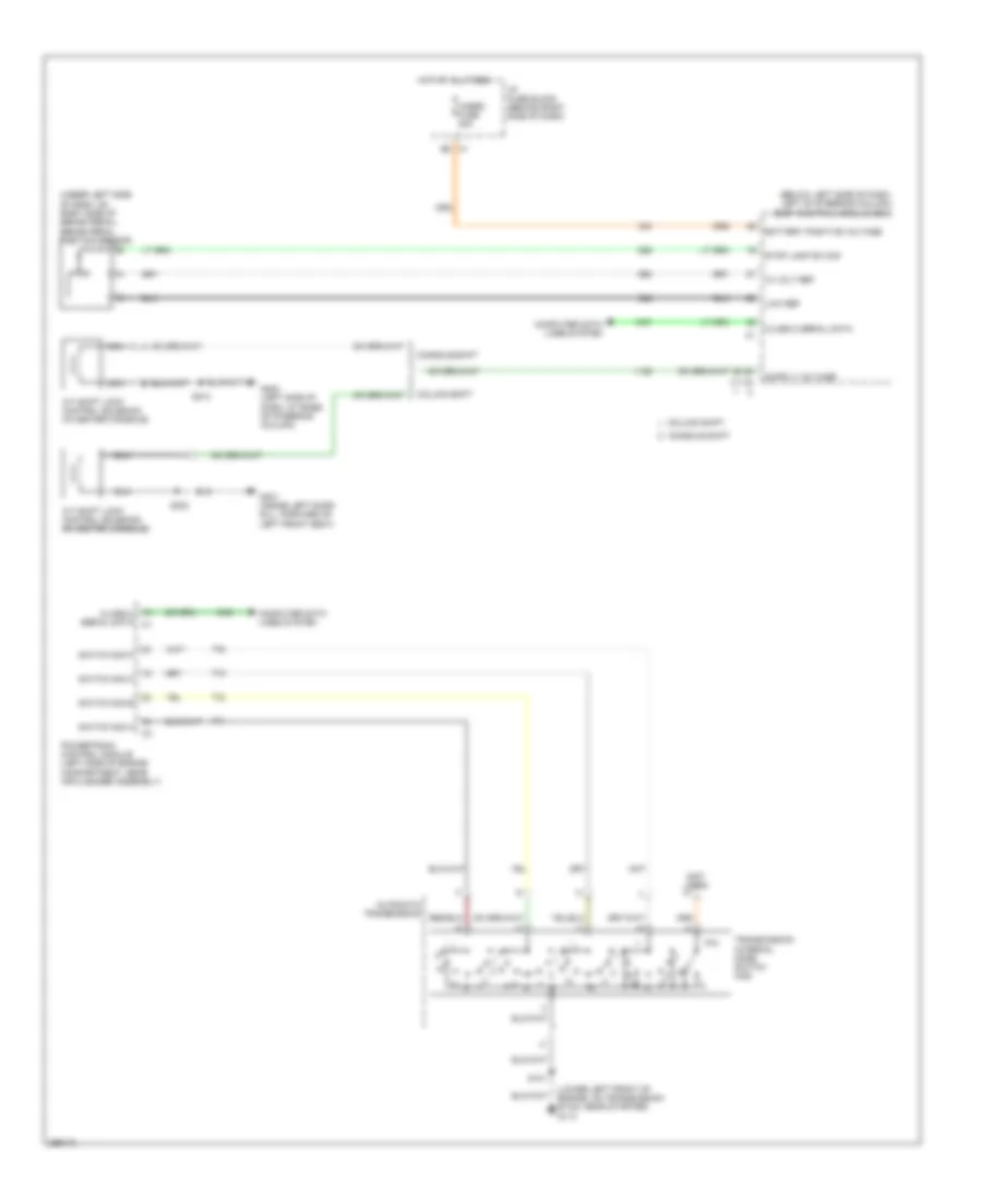
3.6L VIN 7
3.6L VIN 7, Электросхема блокировки селектора для Buick Allure CXL 2007
3.6L VIN 7, Электросхема блокировки селектора для Buick Allure CXL 2007 - Список элементов:
- (below left side of dash, left of steering column) body control module (bcm)
- (mounted to bank 1 cylinder head above exhaust manifold) g115
- (under left side of dash, on right side of brake pedal) brake pedal position sensor
- 5 volt ref
- A/t shift lock control solenoid (in center console)
- Automatic transmission
- Battery positive voltage
- Class 2 serial data
- Computer data lines system
- E5 c1
- Engine control module (ecm) (top of engine)
- G301 (inside left door sill, forward of left front seat)
- Hazrd fuse 20a
- Hi-spd gmlan serial data
- Hot at all times
- I/p fuse block (behind right side of dash)
- Low ref
- Module
- Nca
- P/n
- Park/neutral signal
- S116
- S303
- Stop lamp sw sig
- Switch sig a
- Switch sig b
- Switch sig c
- Switch sig p
- Transmission control
- Transmission internal mode switch (ims)
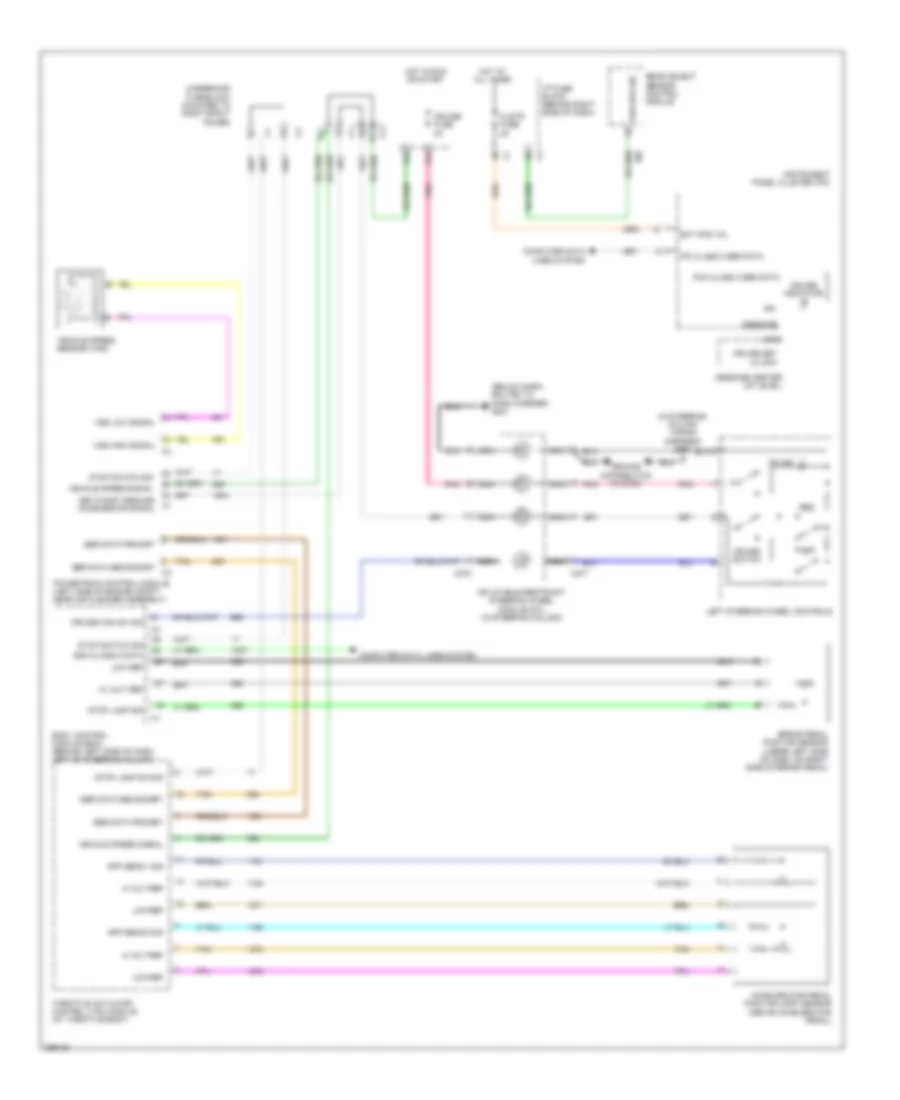
3.8L VIN 2
3.8L VIN 2, Электросхема блокировки селектора для Buick Allure CXL 2007
3.8L VIN 2, Электросхема блокировки селектора для Buick Allure CXL 2007 - Список элементов:
- (below left side of dash, left of steering column) body control module (bcm)
- (lower left front of engine, on transmission stud, near starter) g113
- (not used) w
- (under left side of dash, on right side of brake pedal) brake pedal position sensor
- 10 volt ref
- A/t shift lock control solenoid (in center console)
- A/t shift lock control solenoid (in center console) (in center console)
- Automatic transmission
- Battery positive voltage
- Class 2 serial data
- Class 2 serial data c1
- Column shift
- Computer data lines system
- Console shift
- E5 c1
- G202 (left side of dash, at base of steering column)
- G301 (inside left door sill, forward of left front seat)
- Hazrd fuse 20a
- Hot at all times
- I/p fuse block (behind right side of dash)
- Low ref
- Nca
- P/n
- Powertrain control module (left side of engine compartment, near air cleaner assembly)
- S101
- S214
- S303
- Stop lamp sw sig
- Switch sig a
- Switch sig b
- Switch sig c
- Switch sig p
- Transmission internal mode switch (ims)
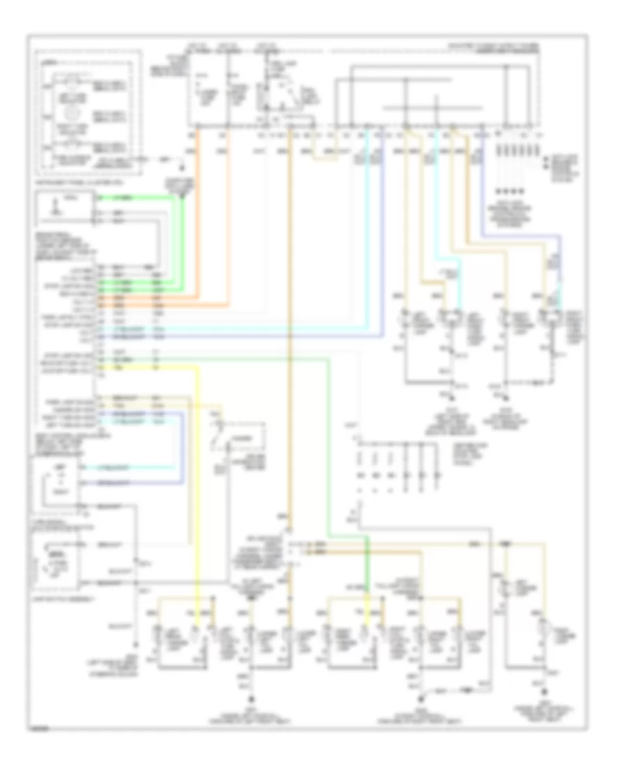
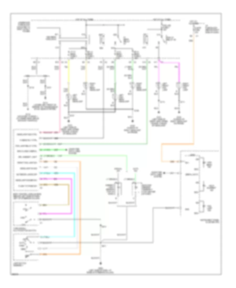
ВНЕШНЕЕ ОСВЕЩЕНИЕ
Электросхема внешнего освещения для Buick Allure CXL 2007
Электросхема внешнего освещения для Buick Allure CXL 2007 - Список элементов:
- (in left taillamp wiring harness) s902
- (in right taillamp wiring harness) s903
- (mounted to right strut tower) underhood fuse block
- 10 volt ref
- Anti-lock brakes & engine controls system
- Anti-lock brakes, engine controls & transmissions systems
- Auto
- Bcm class 2
- Bcm class 2 serial data
- Body control module (bcm) (below left side of dash, left of steering column)
- Brake pedal position sensor (under left side of dash, on right side of brake pedal)
- C1 c2
- C1 e2
- C2 e11
- C2 f9
- C3 a9
- Center high mounted stop lamp (chmsl)
- Chmsl/ bkup fuse 15a
- Computer data lines system
- Driver information center
- G100 (in back of right headlamp on frame)
- G101 (left side of front end upper tie bar, in back of headlamp)
- G202 (left side of dash, at base of steering column)
- G301 (inside left door sill, forward of left front seat)
- G302 (in right door sill, forward of right front seat)
- Hazard
- Hazard sw sig
- Hazrd fuse 20a
- Head
- Hot at all times
- I/p fuse block (behind right side of dash)
- Ign
- Instrument panel cluster (ipc)
- Ipc class 2 serial data
- Lamp switch assembly
- Left
- Left front marker lamp
- Left front park/ turn signal lamp
- Left license lamp
- Left rear marker lamp
- Left tail/ stop & turn signal lamp
- Left turn indicator
- Left turn sw sig
- Logic
- Low ref
- Lower left tail lamp
- Lower right tail lamp
- Lr stop/turn volt
- Off
- Park
- Park lamp on sig
- Park lmp rly ctrl
- Prk lamp fuse 10a
- Prk lamp relay
- Right
- Right front marker lamp
- Right front park/ turn signal lamp
- Right license lamp
- Right rear marker lamp
- Right tail/ stop & turn signal lamp
- Right turn indicator
- Right turn sw sig
- Rr stop/turn volt
- S111
- S112
- S113
- S124
- S211
- S214
- S401
- S402
- S406
- S900
- S901
- Splice pack sp407 (in body wiring harness, under passenger seat, at rear carpet)
- Stop lamp sw sig
- Tan
- Turn audible indicator
- Turn signal/ multi-function switch
- Upper left tail lamp
- Upper right tail lamp
- Volt
- Volt (+)
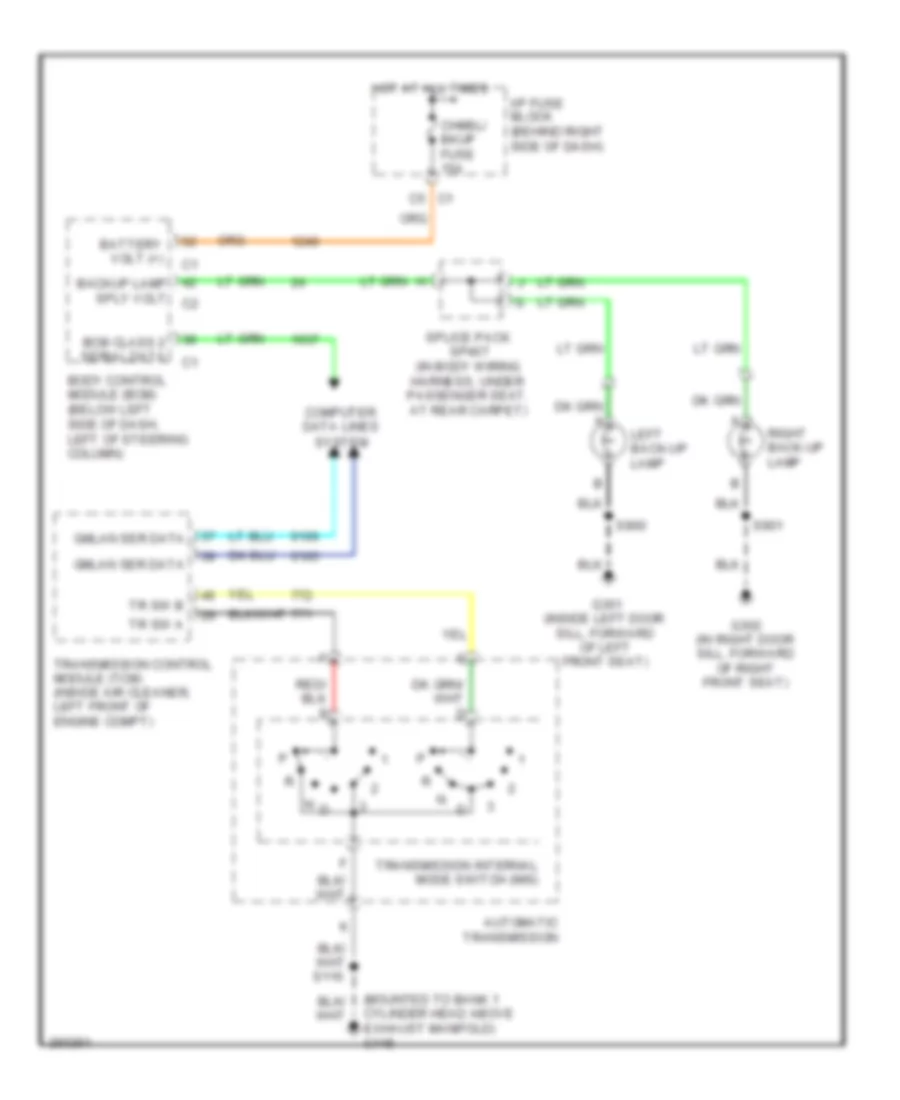
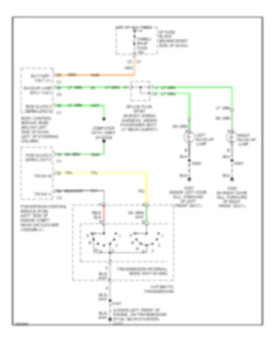
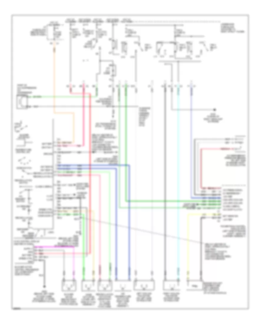
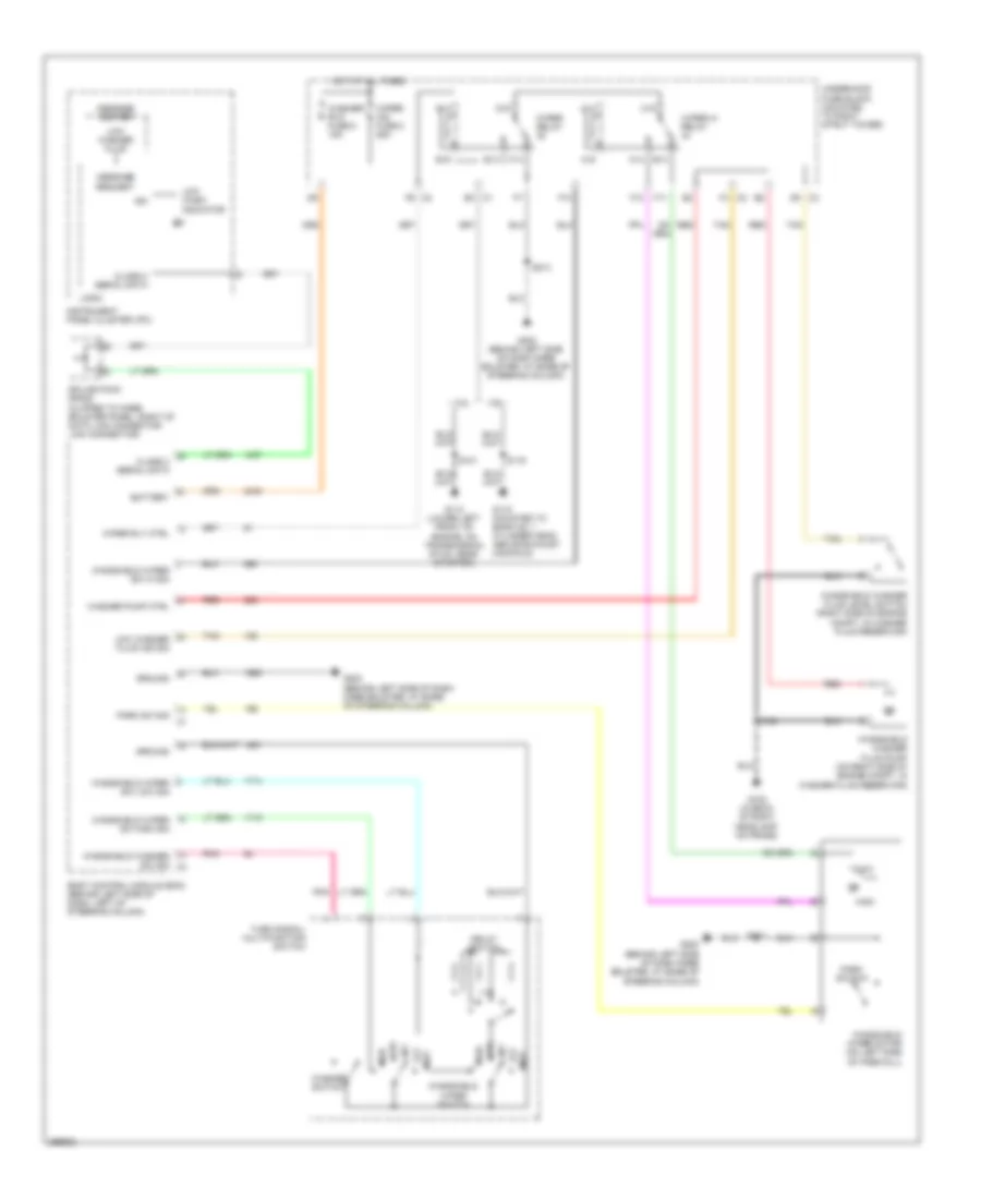
3.6L VIN 7
3.6L VIN 7, Электросхема заднего хода для Buick Allure CXL 2007
3.6L VIN 7, Электросхема заднего хода для Buick Allure CXL 2007 - Список элементов:
- (mounted to bank 1 cylinder head above exhaust manifold) g115
- Automatic transmission
- Backup lamp sply volt
- Battery volt (+)
- Bcm class 2 serial data
- Body control module (bcm) (below left side of dash, left of steering column)
- Chmsl/ bkup fuse 15a
- Computer data lines system
- G301 (inside left door sill, forward of left front seat)
- G302 (in right door sill, forward of right front seat)
- Gmlan ser data
- Hot at all times
- I/p fuse block (behind right side of dash)
- Left back-up lamp
- Right back-up lamp
- S116
- S900
- S901
- Splice pack sp407 (in body wiring harness, under passenger seat, at rear carpet)
- Tr sw a
- Tr sw b
- Transmission control module (tcm) (inside air cleaner, left front of engine compt)
- Transmission internal mode switch (ims)
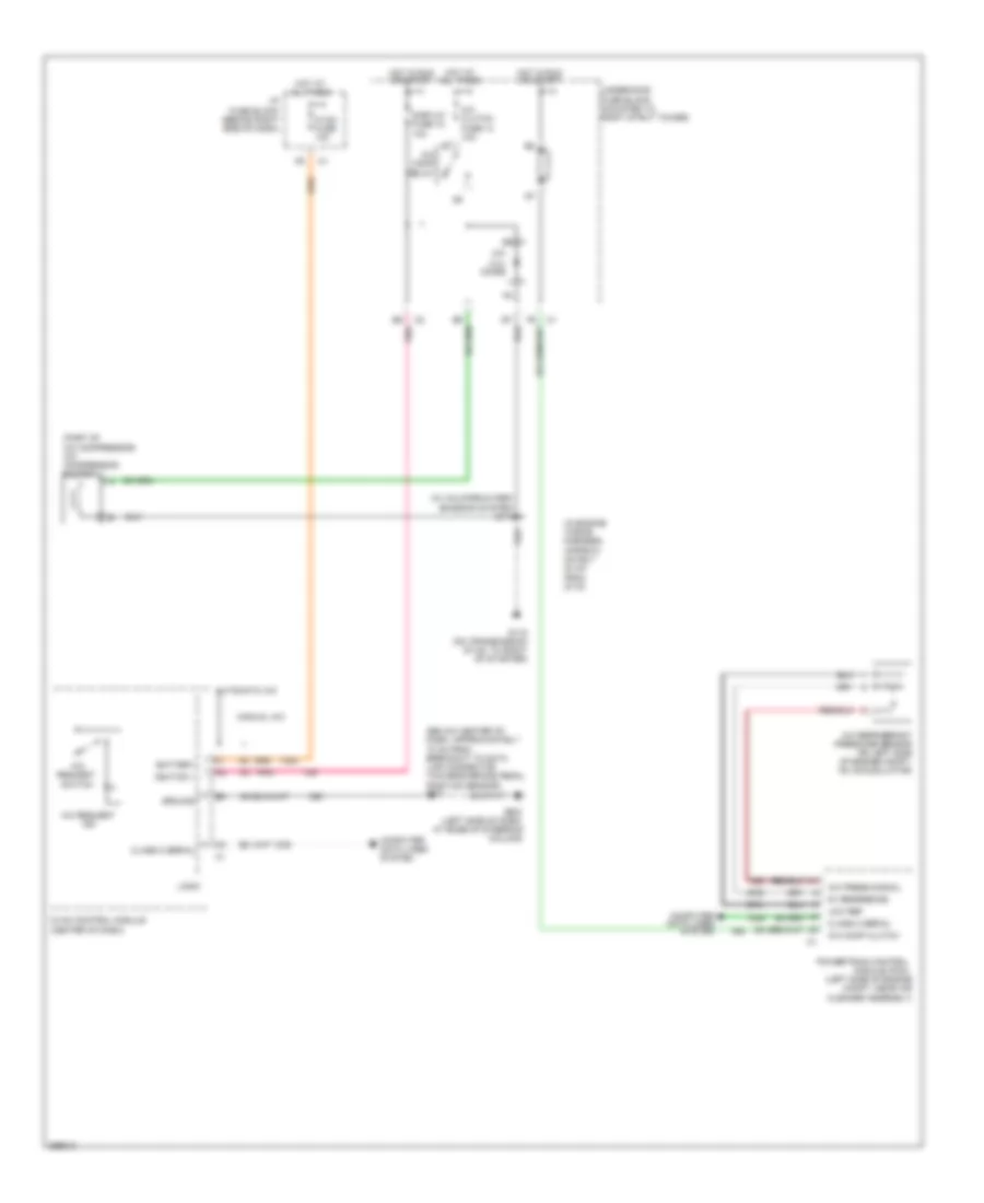
3.8L VIN 2
3.8L VIN 2, Электросхема заднего хода для Buick Allure CXL 2007
3.8L VIN 2, Электросхема заднего хода для Buick Allure CXL 2007 - Список элементов:
- (lower left front of engine, on transmission stud, near starter) g113
- Automatic transmission
- Backup lamp sply volt
- Battery volt (+)
- Bcm class 2 serial data
- Body control module (bcm) (below left side of dash, left of steering column)
- Chmsl/ bkup fuse 15a
- Computer data lines system
- G301 (inside left door sill, forward of left front seat)
- G302 (in right door sill, forward of right front seat)
- Hot at all times
- I/p fuse block (behind right side of dash)
- Left back-up lamp
- Pcm class 2 serial data
- Powertrain control module (pcm) (left side of engine compt, near air cleaner assembly)
- Right back-up lamp
- S101
- S900
- S901
- Splice pack sp407 (in body wiring harness, under passenger seat, at rear carpet)
- Tr sw a
- Tr sw b
- Transmission internal mode switch (ims)
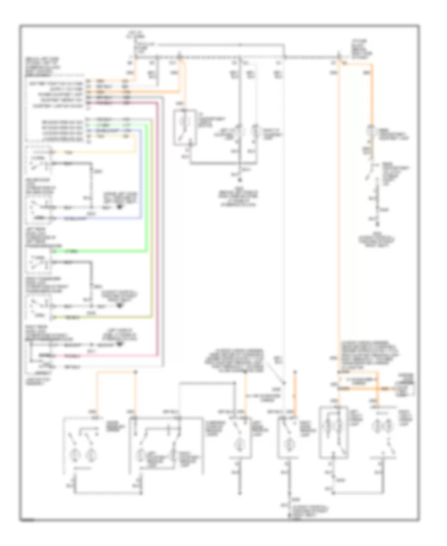
ВНУТРЕННЕЕ ОСВЕЩЕНИЕ
Электросхема подсветки для Buick Allure CXL 2007
Электросхема подсветки для Buick Allure CXL 2007 - Список элементов:
- (below left side of dash, left of steering column) body control module (bcm)
- (in right door sill, forward of right front seat) g302
- (in roof wiring harness, near center of windshield header approximately 10 cm from courtesy/reading lamp - right breakout, towards inside rearview mirror) (w/ onstar) s393
- (in roof wiring harness, near center of windshield header approximately 7.5 cm from courtesy/reading lamp - right breakout, towards inline connector c390)
- (inside left door sill, forward of left front seat) g301
- (left side of dash, at base of steering column) g202
- Battery positive voltage
- Cour-
- Courtesy defeat sw
- Courtesy lamp sw on sig
- D10
- Defeat
- Dome
- Driver door lock (in rear side of driver's door)
- Front passenger door lock (in rear side of front passenger's door)
- G200 (behind left side of dash knee bolster, at base of steering column)
- G302 (in right door sill, forward of right front seat)
- Garage door opener
- Hot at all times
- I/p compartment lamp & switch
- I/p fuse block (behind right side of dash)
- Inside rearview mirror
- Int/illum fuse 10a
- Lamp switch assembly
- Left courtesy/ reading lamp
- Left dome/ reading lamp
- Left i/p courtesy lamp
- Left rear door lock (in rear side of left rear passenger's door)
- Left vanity mirror lamp
- Lf door open sw sig
- Lr door open sw sig
- Off
- Open
- Overhead console reading lamps
- Power courtesy lamp
- Rear compartment courtesy lamp
- Rear compartment lid latch (in rear compt lid)
- Rf door open sw sig
- Right courtesy/ reading lamp
- Right dome/ reading lamp
- Right i/p courtesy lamp
- Right rear door lock (in rear side of right rear passenger's door)
- Right vanity mirror lamp
- Rr door open sw sig
- S211
- S213
- S303
- S308
- S309
- S390
- S398
- S406
- S500
- S604
- Tan
- Tesy lamp
- W/ sunshade mirror
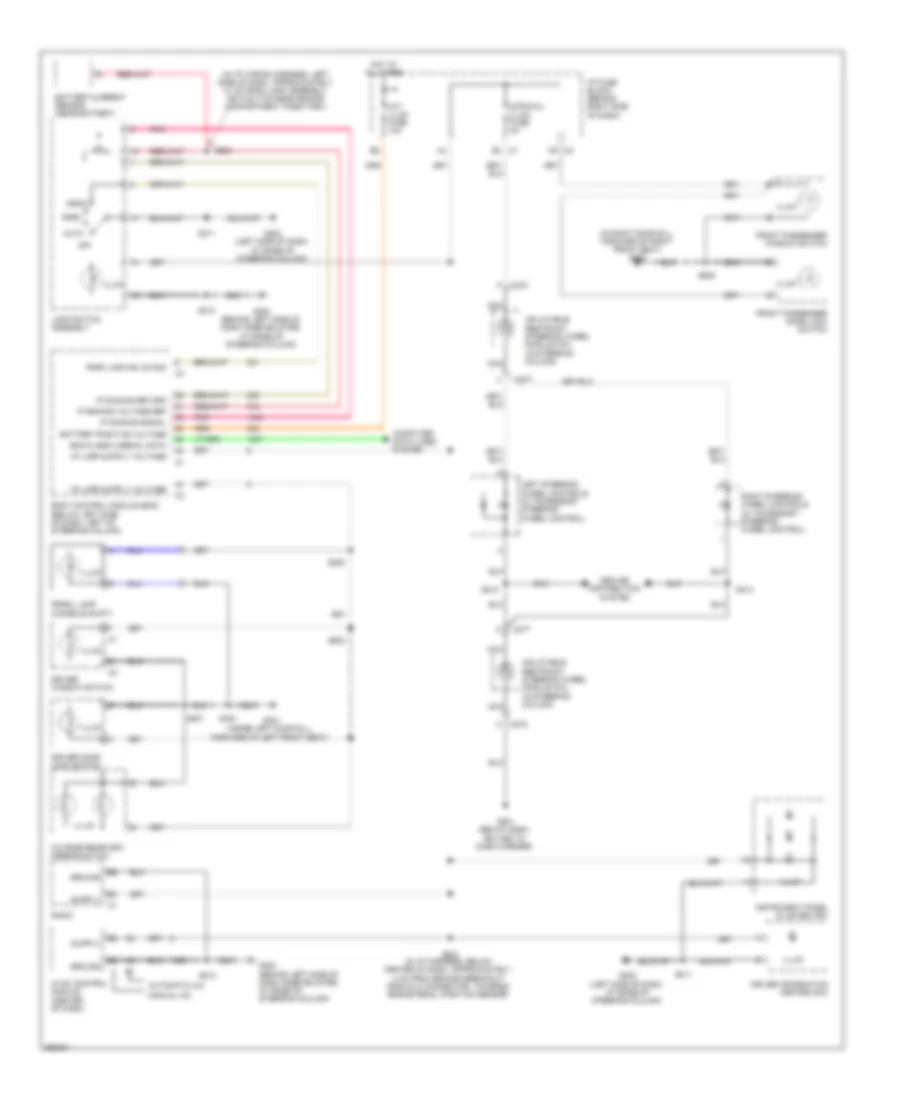
Электросхема подсветки приборов для Buick Allure CXL 2007
Электросхема подсветки приборов для Buick Allure CXL 2007 - Список элементов:
- (in i/p wiring harness, left side of dash, approximately 21 cm from lamp assembly switch towards engine compartment pass-thru)
- (in right door sill, forward of right front seat) g302
- Auto
- Automatic a/c
- Battery current sensor (near battery)
- Battery positive voltage
- Bcm class 2 serial data
- Body control module (bcm) (below left side of dash, left of steering column)
- C c275
- C277
- Computer data lines system
- Driver door lock switch
- Driver information center (dic)
- Driver window switch
- F c275
- Front passenger door lock switch
- Front passenger window switch
- G200 (behind left side of dash knee bolster, at base of steering column)
- G201 (below dash, bolted to dash carrier)
- G202 (left side of dash, at base of steering column)
- G301 (inside left door sill, forward of left front seat)
- Ground
- Ground distribution system
- Head
- Hot at all times
- Hvac control module (center of dash)
- I/p fuse block (behind right side of dash)
- Illum
- Inflatable restraint steering wheel module coil (in steering column)
- Instrument panel cluster (ipc)
- Int/ illum fuse 10a
- Ip dimming return
- Ip dimming signal
- Ip dimming voltage ref
- Lamp switch assembly
- Left steering wheel controls (w/ accessory steering wheel control)
- Manual a/c
- Nca
- Off
- Outside rearview mirror switch
- Park
- Park lamp sw on sig
- Pnk
- Prndl lamp (console shift)
- Radio
- Right steering wheel controls (w/ accessory steering wheel control)
- S203 (in i/p harness, below center of dash, approximately 4 cm from second breakout from dlc connector, towards brake pedal position sensor)
- S204
- S211
- S213
- S214
- S215
- S280
- S303
- S501
- S502
- S605
- Str/whl/ illum fuse 2a
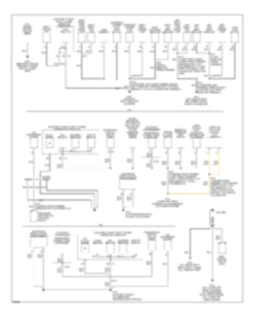
ЗАЗЕМЛЕНИЕ ПОДКЛЮЧЕНИЕ МАССЫ
Электросхема подключение массы заземления (1 из 3) для Buick Allure CXL 2007
Электросхема подключение массы заземления (1 из 3) для Buick Allure CXL 2007 - Список элементов:
- (3.6l) engine control module (ecm)
- (mounted to right strut tower) underhood fuse block
- (sulev) secondary air injection (air) control solenoid valve/ pressure sensor bank 2
- 3.6l
- 3.8l
- A/c clu diode
- A/c clutch diode
- A/c compressor clutch
- Approximately 20 cm from g115)
- Automatic transmission
- B b
- B11
- Battery
- Body control module (bcm)
- C100
- E15
- Electronic brake control module (ebcm)
- Engine oil level switch
- Engine oil pressure (eop) switch
- Except sulev
- Fan 2 relay 46
- Fuel pp relay 41
- G100 (in back of right headlamp on frame)
- G101 (left side of front end upper tie bar, in back of headlamp)
- G102 (3.6l: below right front strut tower) (3.8l: near battery)
- G103 (redundant ground from ecm to even bank cylinder head)
- G111 (3.6l: lower left front of engine, on transmission stud, near starter) (3.8l: lower left side of engine)
- G113 (lower left front of engine, on transmission stud, near starter)
- G115 (mounted to bank 1 cylinder head above exhaust manifold)
- G115 (on transmission stud, to right of starter)
- Hdm beam module 35
- Hood ajar switch
- Horn assembly
- Ign 1 relay 37
- Jumper wiring harness, approximately 5 cm from breakout to left park/turn signal lamp, toward left front fog lamp)
- K14
- Left front fog lamp
- Left front marker lamp
- Left front park/ turn signal lamp
- Left high beam headlamp
- Left low beam headlamp
- Mass air flow (maf)/ intake air temperature (iat) sensor
- Powertrain control module (pcm)
- Right cooling fan
- Right front fog lamp
- Right front marker lamp
- Right front park/ turn signal lamp
- Right high beam headlamp
- Right low beam headlamp
- S101 (in engine wiring harness, in left front of engine compt, approximately 5 cm from breakout to pcm, towards g113)
- S102 (in engine wiring harness. top of engine, approximately 5 cm from breakout to throttle actuator control (tac) module, towards pcm)
- S111
- S112 (in forward lamp harness, approximately 19 cm from left front headlamp assembly)
- S116
- S124 (in forward lamp wiring harness, behind right headlamp, approximately 5 cm from breakout to c142, towards horn assembly)
- S127 (in left headlamp wiring harness)
- Secondary air injection (air) pump (sulev)
- Sulev
- Throttle actuator control (tac) module
- Transmission control module (tcm)
- Transmission internal mode switch (ims)
- Windshield washer fluid level switch
- Windshield washer fluid pump
- Wiper relay 45
- Wiring harness)
Электросхема подключение массы заземления (2 из 3) для Buick Allure CXL 2007
Электросхема подключение массы заземления (2 из 3) для Buick Allure CXL 2007 - Список элементов:
- (3.8l) ignition control module (icm)
- (in on-engine wiring harness, approximately 15.25 cm from g130)
- (in on-engine wiring harness, approximately 30.50 cm from g130)
- (w/ accessory steering wheel control)
- (w/ accessory steering wheel control) right steering wheel controls
- (w/ lumbar seats) driver seat lumbar switch
- 3.6l
- A c2
- A/t shift lock control solenoid
- B c2
- Body control module (bcm)
- C275
- C277
- Driver back heated seat element
- Driver door lock
- Driver door lock switch
- Driver heated seat relay
- Driver outside rearview mirror motor
- Driver seat adjuster switch
- Driver seat belt switch
- Driver window switch
- Electronic compass module
- G112 (in right side of engine, on ignition control module bracket)
- G130 (on cylinder head, front of engine)
- G131 (on cylinder head)
- G201 (below dash, bolted to dash carrier)
- G301 (inside left door sill, forward of left front seat)
- Horn switch
- Ignition coil 1
- Ignition coil 2
- Ignition coil 3
- Ignition coil 4
- Ignition coil 5
- Ignition coil 6
- Inflatable restraint steering wheel module coil
- Left backup lamp
- Left license lamp
- Left rear door lock
- Left rear marker lamp
- Left steering wheel controls
- Left tail/stop & turn signal lamp
- Lower left tail lamp
- Nca
- Outside rearview mirror switch
- Passenger back heated seat element
- Passenger heat seat relay
- Passenger seat adjuster switch
- Passenger seat belt switch
- Prndl lamp
- Rear object sensor control module
- Rear window defogger grid
- Right license lamp
- S130
- S131
- S215 (in steering column wiring harness)
- S330 (in driver seat wiring harness, below driver seat, approximately 4.5 cm from breakout to seat belt switch, towards seat adjuster switch - driver)
- S333 (in front passenger seat wiring harness below front passenger seat, approximately 7 cm from breakout to seat belt pretensioner - rf, towards heated seat relay - front passenger)
- S900 (in left taillamp wiring harness)
- To g301, towards inline connector c355)
- Upper left tail lamp
- W/ console shift
- W/ heated seats
- W/ park assist
- W/ power seats
- W/o power seats
Электросхема подключение массы заземления (3 из 3) для Buick Allure CXL 2007
Электросхема подключение массы заземления (3 из 3) для Buick Allure CXL 2007 - Список элементов:
- (automatic a/c) inside air temperature sensor
- (digital audio system s-band) digital radio receiver
- (gps 1 vehicle communication system) inside rearview mirror
- (in i/p wiring harness, below center of dash, approximately 10 cm from breakout to data link connector towards brake pedal position sensor)
- (in i/p wiring harness, below center of dash, approximately 5 cm from breakout to data link connector towards brake pedal position sensor)
- (in right front door wiring harness, approximately 25.5 cm from breakout to inline connector c304, towards window motor - front passenger)
- (mounted to right strut tower) underhood fuse block
- A/t shift lock control solenoid
- A12 c1
- A15
- A6 c1
- Ambient light sensor
- Audio amplifier
- Automatic a/c
- Auxiliary power outlet
- B8 c1
- Blower motor control processor
- Body control module (bcm)
- Brake fluid level switch
- C1 b5
- Center high mounted stop lamp (chmsl)
- Cigar lighter
- Column shift
- Console shift
- Custom 9 speaker system
- D c1
- Data link connector (dlc)
- Driver information center (dic)
- E15
- F c1
- F14
- F7 c2
- Front passenger door lock
- Front passenger door lock switch
- Front passenger window switch
- Fuel pump & sender assembly
- G c2
- G200 (behind left side of dash knee bolster, at base of steering column)
- G202 (left side of dash, at base of steering column)
- G302 (in right door sill, forward of right front seat)
- Garage door opener
- Gps 1 vehicle communication system
- Hvac control module
- I/p compartment lamp switch
- I/p fuse block (behind right side of dash)
- If equipped
- Ignition lock cylinder control actuator
- Ignition switch
- Inflatable restraint front passenger presence system (pps) module
- Inflatable restraint passenger air bag on/off indicator
- Inflatable restraint sensing & diagnostic module (sdm)
- Instrument panel cluster (ipc)
- Lamp switch assembly
- Left dome/ reading lamp
- Left i/p courtesy lamp
- Left vanity mirror lamp
- Lower right tail lamp
- Manual a/c
- Nca
- Overhead console reading lamps
- Passenger outside rearview mirror motor
- Passenger, towards inline connector c304)
- Radio
- Rear compartment lid latch
- Remote control door lock receiver (rcdlr)
- Right backup lamp
- Right dome/ reading lamp
- Right i/p courtesy lamp
- Right rear door lock
- Right rear marker lamp
- Right tail/stop & turn signal lamp
- Right vanity mirror lamp
- S211
- S213
- S214
- S300
- S309
- S390 (in roof wiring harness, near center of windshield header approximately 20 cm from courtesy/reading lamp - right breakout, towards inside rearview mirror)
- S406 (in body wiring harness, below rear window panel, approximately 9 cm from breakout to inline connector c356, towards g302)
- S604
- S901 (in right taillamp wiring harness)
- Sunload sensor assembly
- Sunroof module
- Theft deterrent exciter module
- Theft led
- Turn signal/ multifunction switch
- Upper right tail lamp
- Vehicle communication interface module (vcim)
- Windshield wiper motor
- Wiper hi relay 44
- Wiper relay 45
Звуковой сигнал Гудок
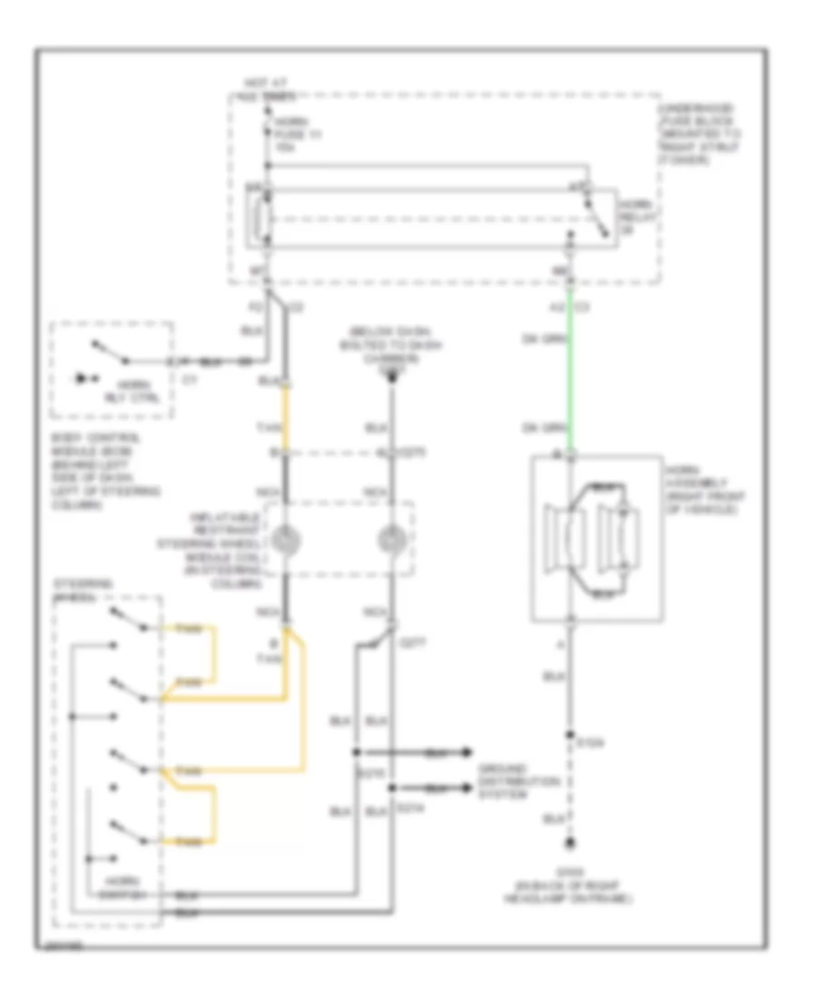
Электросхема звукового сигнал Гудка для Buick Allure CXL 2007
Электросхема звукового сигнал Гудка для Buick Allure CXL 2007 - Список элементов:
- (below dash, bolted to dash carrier) g201
- A2 c3
- Body control module (bcm) (behind left side of dash, left of steering column)
- C275 c
- C277
- G100 (in back of right headlamp on frame)
- Ground distribution system
- Horn assembly (right front of vehicle)
- Horn fuse 11 15a
- Horn relay
- Horn rly ctrl
- Horn switch
- Hot at all times
- Inflatable restraint steering wheel module coil (in steering column)
- Nca
- S124
- S215
- Steering wheel
- Tan
- Underhood fuse block (mounted to right strut tower)
Магнитола Мультимедия
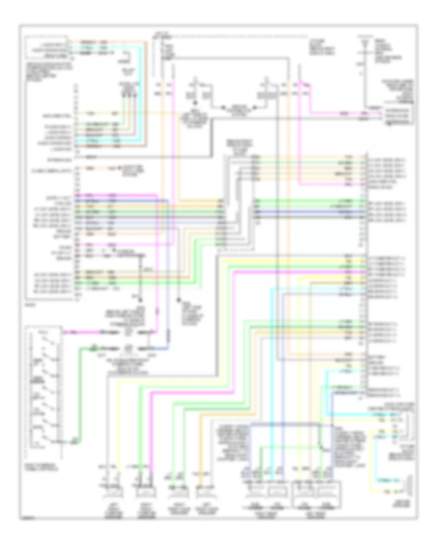
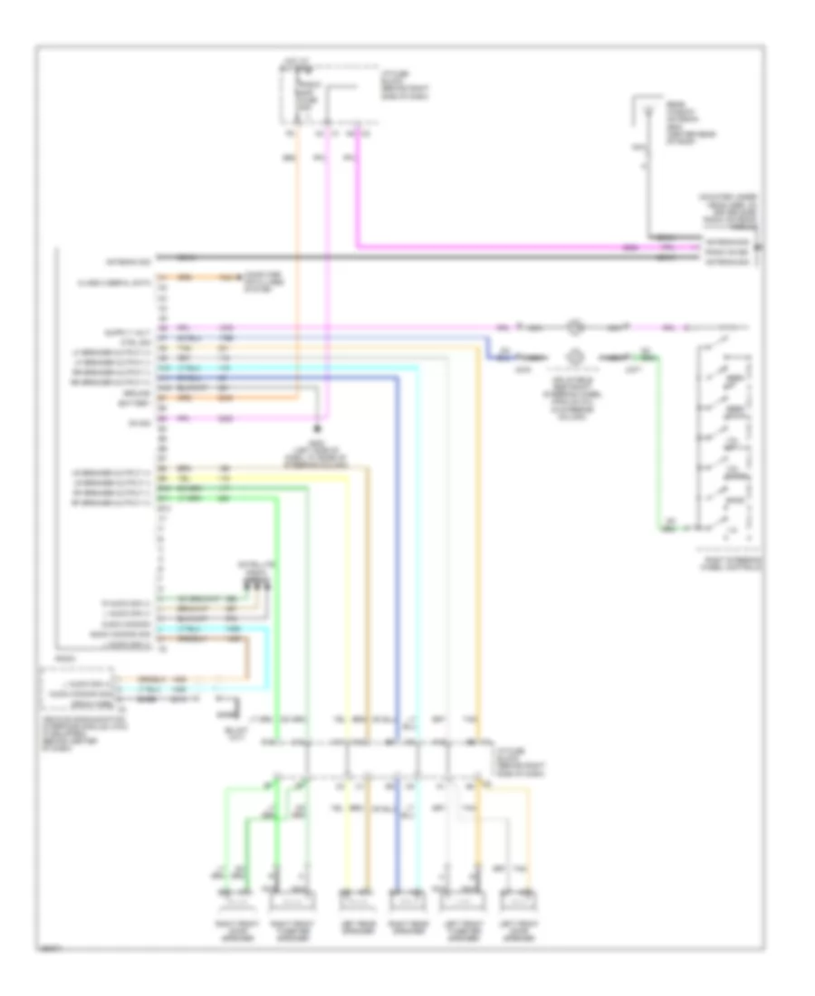
Электросхема магнитолы, С усилитель для Buick Allure CXL 2007
Электросхема магнитолы, С усилитель для Buick Allure CXL 2007 - Список элементов:
- (behind right side of dash) i/p fuse block
- (in body wiring harness, below center of rear window panel, approximately 45 cm from breakout to rear compt courtesy lamp)
- (mounted under headliner, on driver side) radio antenna module
- 1-6
- A10
- A11
- A12
- Amplifier ctrl
- Antenna sig
- Audio amplifier (center of rear compt)
- Audio common
- Audio common sig
- B10
- B11
- B12
- Band
- Bare
- Battery
- C10
- C11
- C12
- C275
- C277
- Center speaker
- Class 2 serial data
- Coax
- Computer data lines system
- Ctrl sig
- Drain wire
- F center out (+)
- F center out (-)
- G200 (behind left side of dash knee bolster, at base of steering column)
- G202 (left side of dash, at base of steering column)
- Ground
- Ground distribution system
- Hot at all times
- I/p fuse block (behind right side of dash)
- I/p lmp vlt
- Inflatable restraint steering wheel module coil (in steering column)
- Interior lights system
- L audio sig
- L audio sig (+)
- Left front door speaker
- Left front tweeter speaker
- Left rear speaker
- Lf low level sig (+)
- Lf low level sig (-)
- Lf spkr out (+)
- Lf spkr out (-)
- Lf tweeter out (+)
- Lf tweeter out (-)
- Lr low level sig (+)
- Lr low level sig (-)
- Lr spkr out (+)
- Lr spkr out (-)
- Mid range
- Nca
- On sig
- R audio sig (+)
- Radio
- Radio on sig
- Rdo/ amp fuse 25a
- Rear sub out (+)
- Rear sub out (-)
- Rear window antenna grid (center rear of roof)
- Rf low level sig (+)
- Rf low level sig (-)
- Rf spkr out (+)
- Rf spkr out (-)
- Rf tweeter out (+)
- Rf tweeter out (-)
- Right front door speaker
- Right front tweeter speaker
- Right rear speaker
- Right steering wheel controls
- Rr low level sig (+)
- Rr low level sig (-)
- Rr spkr out (+)
- Rr spkr out (-)
- S213
- S361
- Satellite radio circuit
- Seek down
- Seek up
- Sub- woofer
- Tan
- Vehicle communication interface module (vcim) (if equipped) (behind center of dash)
- Vol down
- Vol up
Электросхема магнитолы, без Усилитель для Buick Allure CXL 2007
Электросхема магнитолы, без Усилитель для Buick Allure CXL 2007 - Список элементов:
- (mounted under headliner, on driver side) radio antenna module
- 1-6
- A10
- A11
- A12
- A4 c1
- A9 c2
- Antenna sig
- Audio common
- Audio common sig
- B10
- B11
- B12
- Band
- Bare
- Battery
- C10
- C11
- C12
- C275
- C277
- Class 2 serial data
- Coax
- Computer data lines system
- Ctrl sig
- Drain wire
- E nca
- G nca
- G202 (left side of dash, at base of steering column)
- Ground
- Hot at all times
- I/p fuse block (behind right side of dash)
- Inflatable restraint steering wheel module coil (in steering column)
- L audio sig (+)
- Left front door speaker
- Left front tweeter speaker
- Left rear speaker
- Lf speaker output (+)
- Lf speaker output (-)
- Lr speaker output (+)
- Lr speaker output (-)
- Nca
- On sig
- R audio sig (+)
- Radio
- Radio on sig
- Radio/ amp fuse 25a
- Rear window antenna grid (center rear of roof)
- Rf speaker output (+)
- Rf speaker output (-)
- Right front door speaker
- Right front tweeter speaker
- Right rear speaker
- Right steering wheel controls
- Rr speaker output (+)
- Rr speaker output (-)
- Satellite radio circuit
- Seek down
- Seek up
- Tan
- Vehicle communication interface module (vcim) (if equipped) (behind center of dash)
- Vol down
- Vol up
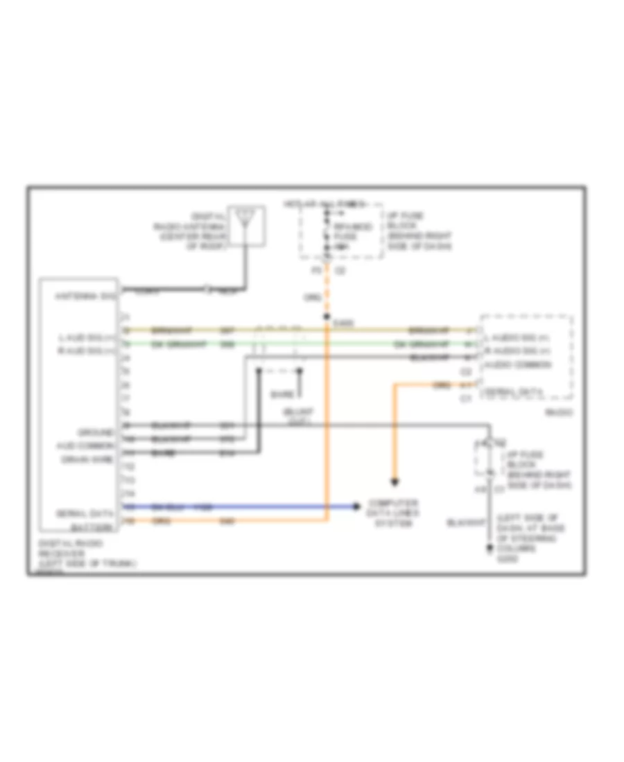
Электросхема спутникового радио для Buick Allure CXL 2007
Электросхема спутникового радио для Buick Allure CXL 2007 - Список элементов:
- (left side of dash, at base of steering column) g202
- Antenna sig
- Aud common
- Audio common
- Bare
- Battery
- Coax
- Computer data lines system
- Digital radio antenna (center rear of roof)
- Digital radio receiver (left side of trunk)
- Drain wire
- Ground
- Hot at all times
- I/p fuse block (behind right side of dash)
- I/p fuse block (behind right side of dash) c1
- L aud sig (+)
- L audio sig (+)
- Nca
- R aud sig (+)
- R audio sig (+)
- Radio
- Rfa/mod fuse 10a
- S400
- Serial data
Навигация GPS Парктроники
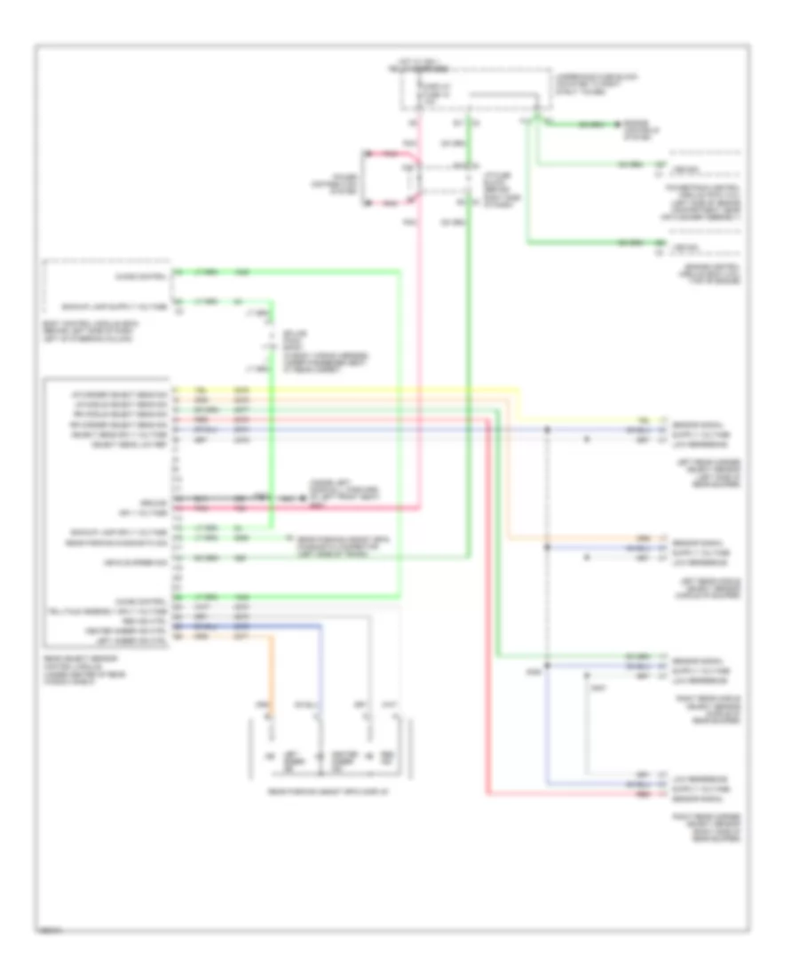
Электросхема парктроников для Buick Allure CXL 2007
Электросхема парктроников для Buick Allure CXL 2007 - Список элементов:
- (inside left door sill, forward of left front seat) g301
- (under center of rear window shelf)
- A rear parking assist (rpa) diagnostic connector (left side of trunk)
- Backup lamp sply voltage
- Body control module (bcm) (behind left side of dash, left of steering column)
- C1 e10
- C2 b11
- C2 e3
- Center amber ind
- Center amber ind ctrl
- Chime control
- D11
- Display fuse 18 10a
- Engine control module (ecm) (3.6l) (top of engine)
- Engine controls system
- F11
- Ground
- Hot w/ ign 1 relay energized
- I/p fuse block (behind right side of dash)
- Ign 1 voltage
- Left amber ind
- Left amber ind ctrl
- Left rear corner object sensor (left side of rear bumper)
- Left rear middle object sensor (middle of bumper)
- Low reference
- Lr corner object sens sig
- Lr middle object sens sig
- Object sens low ref
- Object sens sply voltage
- Pnk
- Power distribution system
- Powertrain control module (pcm) (3.8l) (left side of engine compartment, near air cleaner assembly)
- Rear object sensor control module
- Rear parking assist (rpa) display
- Rear parking diagnostic sig
- Red
- Red ind
- Red ind ctrl
- Right rear corner object sensor (right side of rear bumper)
- Right rear middle object sensor (middle of rear bumper)
- Rr corner object sens sig
- Rr middle object sens sig
- S303
- S450
- S451
- Sensor signal
- Splice pack sp407 (in body wiring harness, under passenger seat, at rear carpet)
- Telltale assembly sply voltage
- Underhood fuse block (mounted to right strut tower)
- Vehicle speed sig
- Vss sig
Подогрев стекол и зеркал
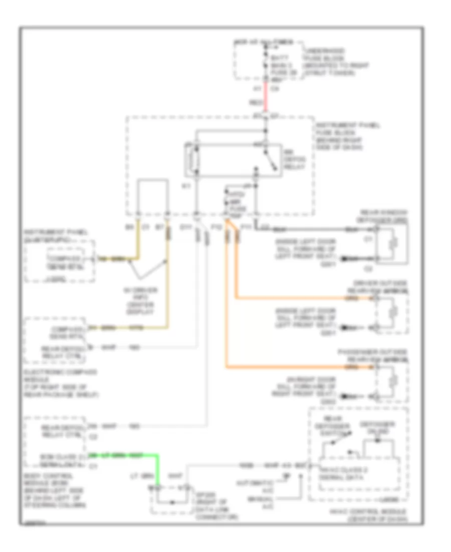
Электросхема подогрева стекол и зеркал для Buick Allure CXL 2007
Электросхема подогрева стекол и зеркал для Buick Allure CXL 2007 - Список элементов:
- (in right door sill, forward of right front seat) g302
- (inside left door sill, forward of left front seat) g301
- Automatic a/c
- Batt main 3 fuse 28 40a
- Bcm class 2 serial data c1
- Body control module (bcm) (behind left side of dash, left of steering column)
- Compass sens rtn
- Defogger on ind
- Driver outside rearview mirror
- Electronic compass module (top right side of rear package shelf)
- F11
- Hot at all times
- Htd/ mir fuse 10a
- Hvac class 2 serial data
- Hvac control module (center of dash)
- Instrument panel cluster (ipc)
- Instrument panel fuse block (behind right side of dash)
- Logic
- Manual a/c
- Passenger outside rearview mirror
- Rear defog relay ctrl
- Rear defog relay ctrl c2
- Rear defogger switch
- Rear window defogger grid
- Red
- Rr defog relay
- Sp205 (right of data link connector)
- Underhood fuse block (mounted to right strut tower)
- W/ driver info center display
ПОДУШКИ БЕЗОПАСНОСТИ AIR BAG
Электросхема подушек безопасности SRS AirBag (1 из 2) для Buick Allure CXL 2007
Электросхема подушек безопасности SRS AirBag (1 из 2) для Buick Allure CXL 2007 - Список элементов:
- (behind right side of dash) inflatable restraint instrument panel (i/p) module
- (in center steering wheel assembly) inflatable restraint steering wheel module
- (in right door sill, forward of right front seat)
- A10
- A11
- A12
- A13
- A14
- A15
- A16
- A17
- A18
- Case ground
- Early production
- G302
- Ground
- I/p stage 1 high
- I/p stage 1 low
- I/p stage 2 high
- I/p stage 2 low
- Ignition 1
- Inflatable restraint sensing & diagnostic module (sdm) (under right front seat)
- Inflatable restraint steering wheel module coil (in steering column)
- L front end sens sig
- L pretensioner high
- L pretensioner low
- L seat belt sw
- L side impact sig
- Late production
- Left inflatable restraint front end sensor (left front of engine compt)
- Left inflatable restraint roof rail module (mounted on left "c" pillar)
- Left inflatable restraint side impact sensor (in lower center of driver's door)
- Lf roof rail mod high
- Lf roof rail mod low
- Low ref
- Nca
- Occupant data link
- Pnk
- R front end sens sig
- R pretensioner high
- R pretensioner low
- R seat belt sw
- R side impact sig
- Red
- Rf roof rail mod high
- Rf roof rail mod low
- Right inflatable restraint front end sensor (right front of engine compt)
- Right inflatable restraint roof rail module (mounted on right "c" pillar)
- Right inflatable restraint side impact sensor (in lower center of front passenger's door)
- Sdm serial data
- Shorting bar
- Stage 1
- Stage 2
- Steer whl stage 1 high
- Steer whl stage 1 low
- Steer whl stage 2 high
- Steer whl stage 2 low
- Tan
- W/ side impact
Электросхема подушек безопасности SRS AirBag (2 из 2) для Buick Allure CXL 2007
Электросхема подушек безопасности SRS AirBag (2 из 2) для Buick Allure CXL 2007 - Список элементов:
- (at base of steering column)
- (in i/p wiring harness, below center of dash, approx 10 cm from breakout to data link connector towards brake pedal position sensor)
- A11
- Air bag ind
- Airbag off
- Airbag on
- B10
- B11
- Batt main 1 fuse 26 40a
- Battery b+
- Case ground
- Class 2 (sdm)
- Class 2 serial data
- Data link connector (dlc) (under left side of dash)
- Driver seat belt switch (in seat belt buckle)
- G202
- G301 (inside left door sill, forward of left front seat)
- G302 (in right door sill, forward of right front seat)
- Ground
- Heated seat sig
- Hot at all times
- Hot in run & start
- Humidity sensor
- I/p fuse block (behind left side of dash)
- Ignition 1
- Inflatable restraint front passenger presence system (pps) module (under front passenger's seat)
- Inflatable restraint front passenger presence system (pps) sensor
- Inflatable restraint passenger air bag on/off indicator
- Instrument panel cluster (ipc)
- Left inflatable restraint seat belt pretensioner (in bottom of driver's seat)
- Logic
- Mass & position
- Nca
- Occupant data link
- Pass airbag off ind
- Pass airbag on ind
- Passenger seat belt indicator
- Passenger seat belt switch (in belt belt buckle)
- Pnk
- Red
- Rfa/mod fuse 10a
- Right inflatable restraint seat belt pretensioner (in bottom of front passenger's seat)
- S211
- S300 (at right front kick panel)
- S330 (in driver seat wiring harness, below driver seat, approximately 4.5 cm from breakout to seat belt switch, towards seat adjuster switch - driver)
- Seat belt ind
- Seatbelt ind
- Seats system
- Shorting bar
- Sir fuse 9 10a
- Splice pack sp205 (clipped to knee bolster panel, right of data link connector)
- Temp sensor
- Underhood fuse block (mounted to right strut tower)
ПРЕДУПРЕЖДАЮЩИЕ СИСТЕМЫ
Электросхема предупреждающей системы (1 из 2) для Buick Allure CXL 2007
Электросхема предупреждающей системы (1 из 2) для Buick Allure CXL 2007 - Список элементов:
- (inside left door sill, forward of left front seat) g301
- Ajar
- Auto
- Battery
- Body control module (bcm) (behind left side of dash, left of steering column)
- Chmsl/ bkup fuse 15a
- Door lock ajar indicator switch
- Dr/lck trunk fuse 15a
- Driver door lock (in rear side of driver's door)
- Ext lmps off input
- G102 (3.6l) (below right front strut tower)
- G102 (3.8l) (near battery)
- G111 (3.6l) (lower left front of engine, on transmission stud, near starter)
- G111 (3.8l) (lower left side of engine)
- G200 (behind left side of dash knee bolster, at base of steering column)
- G201 (below dash, bolted to dash carrier)
- G202 (left side of dash, at base of steering column)
- G301 (inside left door sill, forward of left front seat)
- Ground
- Hazrd fuse 20a
- Head
- Hot at all times
- I/p fuse block (behind right side of dash)
- Ignition switch
- Int/ illum fuse 10a
- Key in ignition switch
- Key in sig
- Lamp switch assembly
- Left rear door lock (in rear side of left rear passenger's door)
- Lf ajar sw sig
- Lr ajar sw sig
- Off
- Park
- Park brake sw
- Park brake switch (on park brake assembly)
- Rf ajar sw sig
- Rr ajar sw sig
- S211
- S214
- S303
- S500
- Serial data
- Underhood fuse block (mounted to right strut tower)
- Washer/ rvc fuse 6 15a
Электросхема предупреждающей системы (2 из 2) для Buick Allure CXL 2007
Электросхема предупреждающей системы (2 из 2) для Buick Allure CXL 2007 - Список элементов:
- (in left front tire at valve stem) left front tire pressure monitor sensor
- (in left rear tire at valve stem) left rear tire pressure monitor sensor
- (in right front tire at valve stem) right front tire pressure monitor sensor
- (in right rear tire at valve stem) right rear tire pressure monitor sensor
- (left side of trunk) digital radio receiver
- (uplevel) message center
- (w/ rke) rear window antenna grid
- A11
- A14
- A16
- Abs/tcs class 2 serial data
- Ajar
- Antenna signal
- Check tire pressure indicator
- Check tire pressure service tire monitor
- Class 2
- Class 2 a1
- Door lock ajar indicator switch
- Driver seat belt switch (in seat belt buckle)
- Front passenger door lock (in rear side of front passenger's door)
- G301 (inside left door sill, forward of left front seat)
- G302 (in right door sill, forward of right front seat)
- Hot at all times
- I/p fuse block (behind right side of dash)
- Ign
- Inflatable restraint passenger air bag on/off indicator
- Inflatable restraint sensing & diagnostic module (sdm) (under right front seat)
- Instrument panel cluster (ipc)
- Ipc class 2 serial data
- Left seat belt sw
- Logic
- Message request
- Nca
- Pass seat belt ind
- Passenger seat belt switch (in seat belt buckle)
- Pnk
- Radio
- Red
- Remote control door lock receiver (rcdlr) (on right side of dash, below defroster panel)
- Rfa class 2 serial data
- Right rear door lock (in rear side of right rear passenger's door)
- Right seat belt sw
- S406
- S604
- Sdm class 2 serial data
- Seat belt indicator
- Serial data
- Sir fuse 9 10a
- Solid state
- Sp205 (clipped to knee bolster panel, right of data link connector)
- Underhood fuse block (mounted to right strut tower)
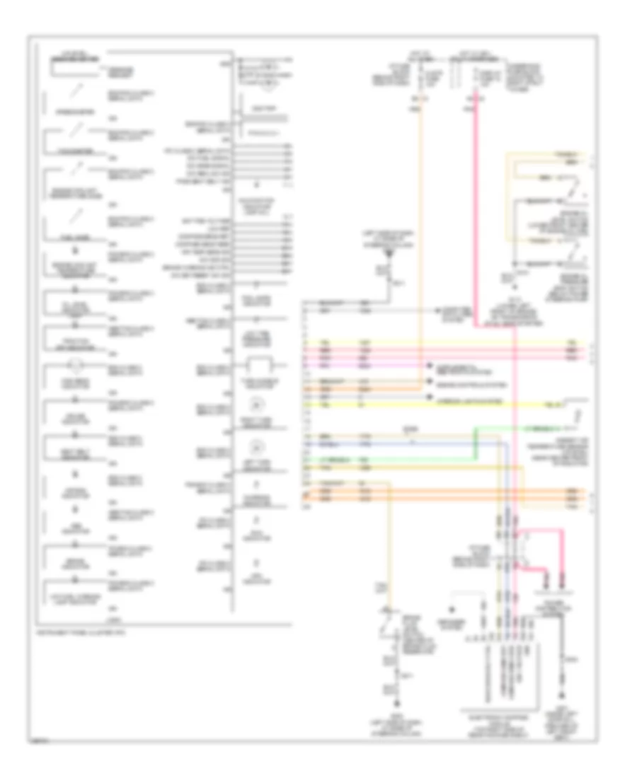
ПРИБОРНАЯ ПАНЕЛЬ
Электросхема панели приборов, С Центр сообщений (1 из 2) для Buick Allure CXL 2007
Электросхема панели приборов, С Центр сообщений (1 из 2) для Buick Allure CXL 2007 - Список элементов:
- (left side of dash, at base of steering column) g202
- (uplevel) message center
- Abs indicator
- Abs/tcs class 2 serial data
- Air bag indicator
- Air temp sens sig
- Ambient air temperature sensor (uplevel) (near center front of radiator)
- B10
- Base
- Bat pos voltage
- Bcm class 2 serial data
- Brake fluid level switch (center of brake fluid reservoir)
- Brake indicator
- Brake warning ind ctrl
- Charging indicator
- Clstr fuse 10a
- Compass sens feed
- Compass sens ret
- Computer data lines system
- Cruise indicator
- D11
- Defogger system
- Dic fuel signal
- Dic gage signal
- Dic menu sw sig
- Dic odo sig
- Dic set/reset sw sig
- Display fuse 18 10a
- Ecm/pcm class 2 serial data
- Electronic compass module (top right side of rear package shelf)
- Engine controls system
- Engine coolant temperature gage
- Engine coolant temperature indicator
- Engine oil level switch (lower front center of engine oil pan)
- Engine oil pressure (eop) switch (below power steering pump)
- Fog lamps indicator
- Fuel gage
- G113 (lower left front of engine, on transmission stud, near starter)
- G202 (left side of dash, at base of steering column)
- G301 (inside left door sill, forward of left front seat)
- Gnd
- High beam indicator
- Hot at all times
- Hot w/ ign 1 relay energized
- I/p fuse block (behind right side of dash)
- Ign
- Ign 1 voltage
- Instrument panel cluster (ipc)
- Interior lights system
- Ipc class 2 serial data
- Ipc/bcm class 2 serial data
- Km/h indicator
- Left turn indicator
- Logic
- Low fuel warning lamp indicator
- Low ref
- Low tire pressure indicator
- Malfunction indicator lamp (mil)
- Message request
- Mph indicator
- Odo/trip
- Oil level indicator lamp
- P r n d 3 2 1
- Pass seat belt ind
- Pcm/ecm class 2 serial data
- Pnk
- Power distribution system
- Rear defog rly ctrl
- Red
- Right turn indicator
- S211
- S303
- Sdm class 2 serial data
- Seat belt indicator
- Speedometer
- Tachometer
- Tan
- Traction off indicator
- Turn audible indicator
- Underhood fuse block (mounted to right strut tower)
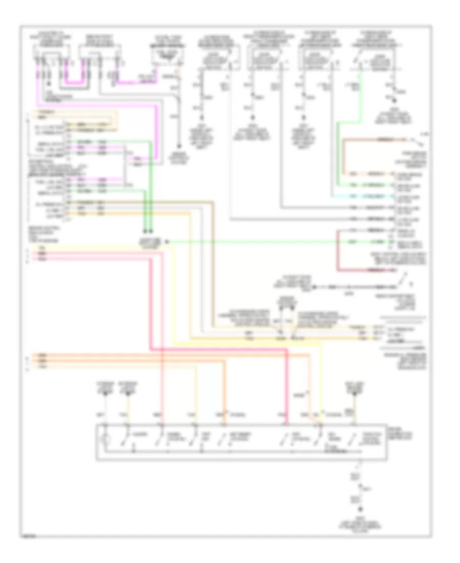
Электросхема панели приборов, С Центр сообщений (2 из 2) для Buick Allure CXL 2007
Электросхема панели приборов, С Центр сообщений (2 из 2) для Buick Allure CXL 2007 - Список элементов:
- (3.8l)
- (behind right side of dash) i/p fuse block
- (in fuel tank) fuel pump & sender assembly
- (in on-engine wiring harness, approximately 34.5 cm from engine control module)
- (in rear side of driver's door) driver door lock
- (in rear side of front passenger's door) front passenger door lock
- (in rear side of left rear passenger's door) left rear door lock
- (in rear side of right rear passenger's door) right rear door lock
- (in right door sill, forward of right front seat) g302
- (mounted to right strut tower) underhood fuse block
- 3.6l
- 3.8l
- 5v ref 1
- A12
- Air conditioning system
- Anti-lock brakes system
- B12
- Base
- Bcm class 2 serial data c1
- Body control module (bcm) (below left side of dash, left of steering column)
- Computer data lines system
- Control module)
- Door lock ajar indicator switch
- Driver information center (dic)
- E/m (base)
- Engine control module (ecm) (3.6l) (top of engine)
- Engine controls system
- Engine oil pressure (eop) sensor (left front of engine block)
- Exterior lights system
- Fuel (uplevel)
- Fuel level sensor
- Fuel lvel sig
- G202 (left side of dash, at base of steering column)
- G301 (inside left door sill, forward of left front seat)
- G302 (in right door sill, forward of right front seat)
- Gages (uplevel)
- Hazard
- Info (uplevel)
- Interior lights system
- Lf dr ajar sw sig
- Logic
- Low ref
- Lr dr ajar sw sig
- Nca
- Oil lvl sw sig
- Oil press sw
- Park brake sw sig
- Park brake switch (on park brake assembly)
- Pnk
- Powertrain control module (pcm) (left side of engine compt, near air cleaner assembly)
- Rear compartment lid latch (in rear compt lid)
- Rear lid ajar sw c2
- Red
- Rf dr ajar sw sig
- Rr dr ajar sw sig
- S119
- S120
- S211
- S303
- S406
- S500
- S604
- Serial data
- Set/reset (uplevel)
- Tan
- Traction control (uplevel)
- Trip odo
- Uplevel
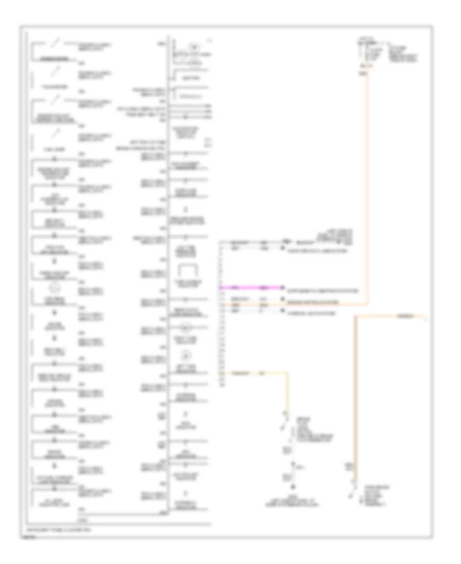
Электросхема панели приборов, без Центр сообщений (1 из 2) для Buick Allure CXL 2007
Электросхема панели приборов, без Центр сообщений (1 из 2) для Buick Allure CXL 2007 - Список элементов:
- (left side of dash, at base of steering column) g202
- Abs indicator
- Abs/tcs class 2 serial data
- Air bag indicator
- Bat pos voltage
- Bcm class 2 serial data
- Brake fluid level switch (center of brake fluid reservoir)
- Brake indicator
- Brake warning ind ctrl
- Change oil indicator
- Charging indicator
- Check gas cap indicator
- Clstr fuse 10a
- Computer data lines system
- Cruise indicator
- Door ajar indicator
- E8 c1
- Engine controls system
- Engine coolant temperature gage
- Engine coolant temperature indicator
- Fuel gage
- G202 (left side of dash, at base of steering column)
- Gnd
- Hdlp suggest indicator
- High beam indicator
- Hot at all times
- I/p fuse block (behind right side of dash)
- Ign
- Ign pcm class 2 serial data
- Ign pcm/ecm class 2 serial data
- Instrument panel cluster (ipc)
- Interior lights system
- Ipc class 2 serial data
- Ipc/bcm class 2 serial data
- Km/h indicator
- Left turn indicator
- Logic
- Low coolant indicator
- Low fuel warning lamp indicator
- Low ref
- Low tire pressure indicator
- Low washer fluid indicator
- Malfunction indicator lamp (mil)
- Mph indicator
- Odo/trip
- Oil level indicator lamp
- P r n d 3 2 1
- Park brake switch (on park brake assembly)
- Pass seat belt ind
- Pcm class 2 serial data
- Pcm/ecm class 2 serial data
- Rear hatch ajar indicator
- Reduced engine power indicator
- Right turn indicator
- S211
- Sdm class 2 serial data
- Seat belt indicator
- Security indicator
- Service vehicle soon indicator
- Speedometer
- Tachometer
- Traction off indicator
- Turn audible indicator
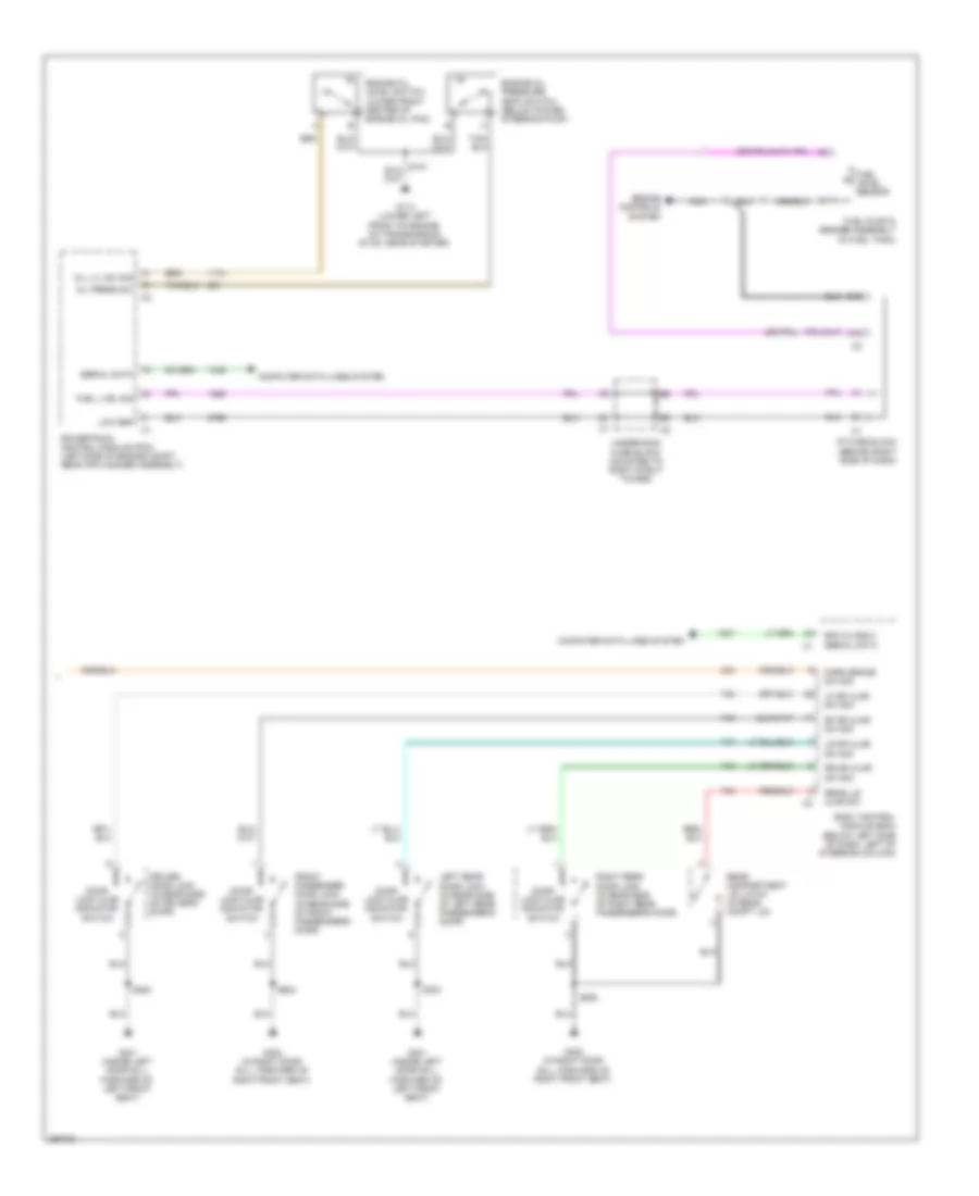
Электросхема панели приборов, без Центр сообщений (2 из 2) для Buick Allure CXL 2007
Электросхема панели приборов, без Центр сообщений (2 из 2) для Buick Allure CXL 2007 - Список элементов:
- A12
- B12
- Bcm class 2 serial data
- Body control module (bcm) (below left side of dash, left of steering column)
- Computer data lines system
- Door lock ajar indicator switch
- Driver door lock (in rear side of driver's door)
- Engine controls system
- Engine oil level switch (lower front center of engine oil pan)
- Engine oil pressure (eop) switch (below power steering pump)
- Front passenger door lock (in rear side of front passenger's door)
- Fuel level sensor
- Fuel lvel sig
- Fuel pump & sender assembly (in fuel tank)
- G113 (lower left front of engine, on transmission stud, near starter)
- G301 (inside left door sill, forward of left front seat)
- G302 (in right door sill, forward of right front seat)
- I/p fuse block (behind right side of dash)
- Left rear door lock (in rear side of left rear passenger's door)
- Lf dr ajar sw sig
- Low ref
- Lr dr ajar sw sig
- Nca
- Oil lvl sw sig
- Oil press sw
- Park brake sw sig
- Powertrain control module (pcm) (left side of engine compt, near air cleaner assembly)
- Rear compartment lid latch (in rear compt lid)
- Rear lid ajar sw
- Rf dr ajar sw sig
- Right rear door lock (in rear side of right rear passenger's door)
- Rr dr ajar sw sig
- S303
- S406
- S500
- S604
- Serial data
- Underhood fuse block (mounted to right strut tower)
ПРИВОД ЗЕРКАЛ
Электросхема затемняющегося зеркала заднего вида для Buick Allure CXL 2007
Электросхема затемняющегося зеркала заднего вида для Buick Allure CXL 2007 - Список элементов:
- (in right door sill, forward of right front seat) g302
- Ambient light sensor ind
- Body control module (bcm) (below left side of dash, left of steering column)
- Button back lighting
- Cellular micro phone signal
- Drain wire
- Emergency ind
- Emergency switch
- F1 c2
- Ground
- Headlight sensor ind
- High
- Hot at all times
- I/p fuse block (behind right side of dash)
- Inside rearview mirror
- Interior lights system
- Keypad green led ind
- Keypad green led signal
- Keypad red led ind
- Keypad red led signal
- Keypad signal
- Logic
- Low
- Max
- Micro phone
- Min
- Nca
- Off
- Onstar ind
- Onstar keypad
- Onstar switch
- Phone ind
- Phone switch
- Power tops system
- S/roof fuse 20a
- S390
- S394 (w/ sunroof)
- Splice pack sp407 (under passenger seat, at rear carpet)
- Vehicle communication interface module (vcim) (w/ on star) (behind center of dash)
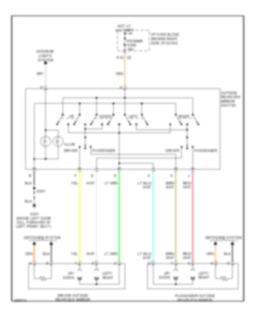
Электросхема привода зеркал для Buick Allure CXL 2007
Электросхема привода зеркал для Buick Allure CXL 2007 - Список элементов:
- Defogger system
- Down
- Driver
- Driver outside rearview mirror
- E12
- G301 (inside left door sill, forward of left front seat)
- Hot at all times
- I/p fuse block (behind right side of dash)
- Illum
- Interior lights system
- Left
- Left/ right
- Outside rearview mirror switch
- Passenger
- Passenger outside rearview mirror
- Pwr/mir fuse 10a
- Right
- S501
- Up/ down
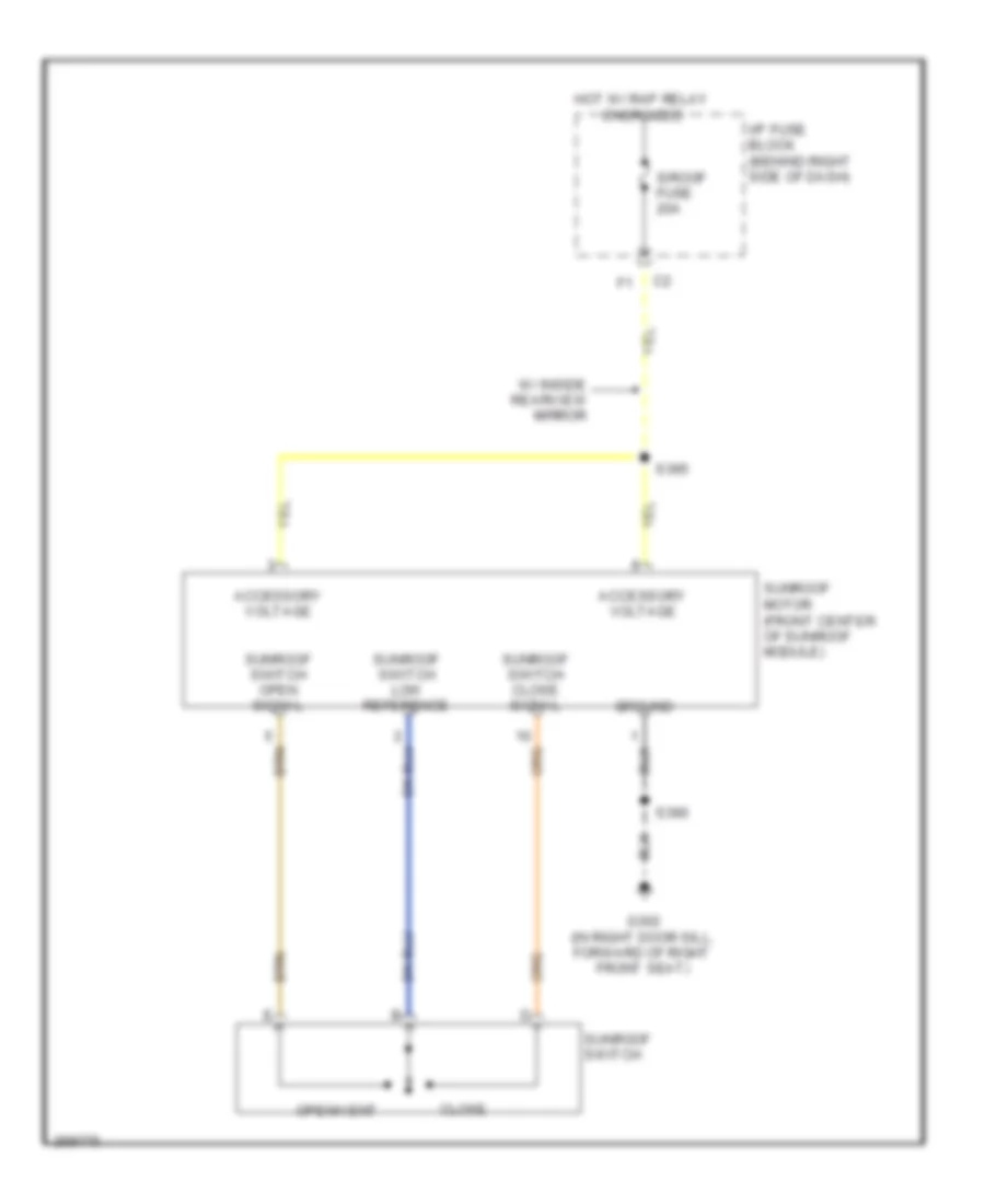
ПРИВОД ЛЮКА И КРЫШИ
Электросхема привода люка или крыши для Buick Allure CXL 2007
Электросхема привода люка или крыши для Buick Allure CXL 2007 - Список элементов:
- Accessory voltage
- Close
- G302 (in right door sill, forward of right front seat)
- Ground
- Hot w/ rap relay energized
- I/p fuse block (behind right side of dash)
- Open/vent
- S/roof fuse 20a
- S390
- S395
- Sunroof motor (front center of sunroof module)
- Sunroof switch
- Sunroof switch close signal
- Sunroof switch low reference
- Sunroof switch open signal
- W/ inside rearview mirror
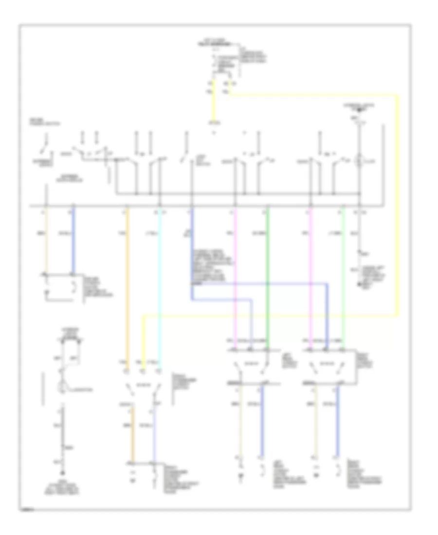
ПРИВОД СТЕКЛОПОДЪЕМНИКОВ
Электросхема стеклоподъемников для Buick Allure CXL 2007
Электросхема стеклоподъемников для Buick Allure CXL 2007 - Список элементов:
- (in body wiring harness, below left side of driver seat, approximately 26 cm from breakout g301 towards inline connector c355) s350
- (inside left door sill, forward of left front seat) g301
- C1 f
- C2 e
- Down
- Driver window motor (center of driver's door)
- Driver window switch
- Express down
- Express down module
- Front passenger window motor (center of front passenger's door)
- Front passenger window switch
- G302 (in right door sill, forward of right front seat)
- Hot w/ rap relay energized
- I/p fuse block (behind right side of dash)
- Illum
- Illumination
- Interior lights system
- Left rear window motor (center of left rear passenger door)
- Left rear window switch
- Lock out switch
- Pwr/wndw circuit breaker 25a
- Right rear window motor (center of right rear passenger door)
- Right rear window switch
- S501
- S605
- Tan
Противоугонная система Сигнализация
Электросхема открывания авто для Buick Allure CXL 2007
Электросхема открывания авто для Buick Allure CXL 2007 - Список элементов:
- (if equipped) rear window antenna grid
- (in body wiring harness, below right front passenger seat, approximately 26 cm from second breakout to g301, towards inflatable restraint sensing & diagnostic module) s315
- (in body wiring harness, below right side of front passenger seat, approximately 29 cm from second breakout to inline connector c311, towards inflatable restraint sensing & diagnostic module)
- (inside left door sill, forward of left front seat) g301
- (on right side of dash, below defroster panel) remote control door lock receiver (rcdlr)
- A5 c2
- Ajar
- Ajar sw sig
- Antenna sig
- Bcm class 2
- Body control module (bcm) (below left side of dash, left of steering column)
- Class 2
- Coax
- Computer data lines system
- Door ajar
- Door ajar indicator
- Door lock actuator
- Door lock ajar indicator switch
- Door lock cylinder switch
- Door lock open indicator switch
- Dr ajar sw sig
- Dr open sw sig
- Dr/lck trunk fuse 15a
- Driver door lock (in rear side of driver's door)
- Driver door lock switch
- Front passenger door lock (in rear side of front passenger's door)
- Front passenger door lock switch
- G202 (left side of dash, at base of steering column)
- G301 (inside left door sill, forward of left front seat)
- G302 (in right door sill, forward of right front seat)
- Ground
- Headlights system exterior lights system
- Hi beam relay
- Horn rly ctrl
- Horns system
- Hot at all times
- I/p fuse block (behind right side of dash)
- Instrument panel cluster (ipc)
- Interior lights system
- Lamp rly ctrl
- Left rear door lock (in rear side of left rear passenger's door)
- Lid ajar sw
- Lock
- Lock ctrl
- Lock sig
- Logic
- Message center
- Nca
- Open
- Pnk
- Power distribution system
- Rear compartment lid latch (in rear compt lid)
- Rfa ser data
- Rfa/mod fuse 10a
- Right rear door lock (in rear side of right rear passenger's door)
- S211
- S300
- S303
- S314
- S400 (w/ digital audio system)
- S406
- S500
- S501
- S604
- S605
- Scrty ind ctrl
- Security indicator
- Sw sig
- Tan
- Theft led
- Trunk ajar
- Trunk ajar indicator
- Unlock
- Unlock ctrl
- Unlock sig
- Volt (+)
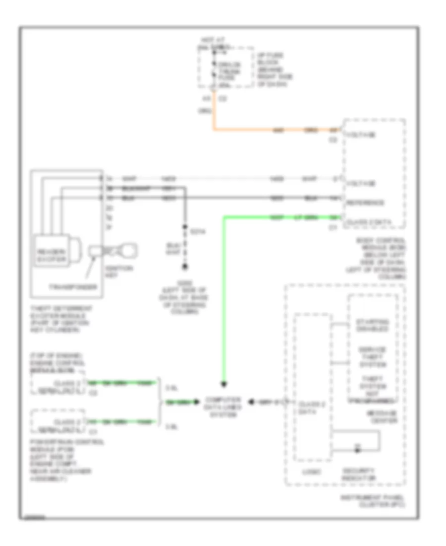
схема отмычки для Buick Allure CXL 2007
схема отмычки для Buick Allure CXL 2007 - Список элементов:
- (top of engine) engine control module (ecm)
- 3.6l
- 3.8l
- Body control module (bcm) (below left side of dash, left of steering column)
- Class 2 data
- Class 2 serial data
- Computer data lines system
- Dr/lck trunk fuse 15a
- G202 (left side of dash, at base of steering column)
- Hot at all times
- I/p fuse block (behind right side of dash)
- Ignition key
- Instrument panel cluster (ipc)
- Logic
- Message center
- Powertrain control module (pcm) (left side of engine compt, near air cleaner assembly)
- Reader/ exciter
- Reference
- S214
- Security indicator
- Service theft system
- Starting disabled
- Theft deterrent exciter module (part of ignition key cylinder)
- Theft system not programmed
- Transponder
- Voltage
СИСТЕМА АНТИБЛОКИРОВОЧНОЙ ТОРМОЗНОЙ СИСТЕМЫ ABS
Электросхема антиблокировочной тормозной системы АБС (ABS) (1 из 2) для Buick Allure CXL 2007
Электросхема антиблокировочной тормозной системы АБС (ABS) (1 из 2) для Buick Allure CXL 2007 - Список элементов:
- (left side of engine compt, part of brake pressure modulator valve) electronic brake control module (ebcm)
- 3.6l
- 3.6l w/
- 3.8l
- 5-volt reference
- A11
- A2 c2
- A9 c1
- Abs fuse 23 10a
- Abs mtr fuse 31 40a
- Abs sol fuse 19 25a
- Abs/tcs class 2 serial data
- Active brake control
- B+ motor control
- B+ sol valve control
- Battery
- Brake control
- Brake pressure modulator valve (bpmv)
- Brake pressure sensor signal
- C2 c4
- C5 c1
- Computer data lines system
- Del torque sig
- Delivered torque signal
- Ecm class 2 ser data
- Eng speed sig
- Eng speed sig (3.8l)
- Engine control module (3.6l) (top of engine)
- Engine controls system
- G115 (3.6l: mounted to bank 1 cylinder head above exhaust manifold) (3.8l: on transmission stud, to right of starter)
- Ground
- Hi spd gmlan ser data +
- Hi spd gmlan ser data - (3.6l)
- Hot at all times
- Hot w/ ign 1 relay energized
- Hsv 2 (w/ tcs)
- Hsv1 (w/ tcs)
- Ign 1
- Lateral accelerometer signal
- Left front inlet
- Left front outlet
- Left rear inlet
- Left rear outlet
- Lf wheel speed sens low ref
- Lf wheel speed sens sig
- Lr wheel speed sens low ref
- Lr wheel speed sens sig
- Magnasteer actuator (on steering rack assembly)
- Pcm class 2 ser data
- Pnk
- Powertrain control module (3.8l) (left side of engine compartment, near air cleaner assembly)
- Pump motor
- Red
- Req torque sig
- Requested torque signal
- Rf wheel speed sens low ref
- Rf wheel speed sens sig
- Right front inlet
- Right front outlet
- Right rear inlet
- Right rear outlet
- Rr wheel speed sens low ref
- Rr wheel speed sens sig
- Solenoid valves
- Stop lamp sw sig
- Tan
- Underhood fuse block (mounted to right strut tower)
- Usv 1 (w/ tcs)
- Usv 2 (w/ tcs)
- Var effort steer act cntrl
- Var effort steer act pwr
- W/ active
- W/ traction control
- W/o
- Yaw rate sensor signal
- Yaw rate sensor test control
Электросхема антиблокировочной тормозной системы АБС (ABS) (2 из 2) для Buick Allure CXL 2007
Электросхема антиблокировочной тормозной системы АБС (ABS) (2 из 2) для Buick Allure CXL 2007 - Список элементов:
- (left side of dash, at base of steering column) g202
- (on left front wheel hub assembly) left front wheel speed sensor (wss)
- (on left rear wheel hub assembly) left rear wheel speed sensor (wss)
- (on right front wheel hub assembly) right front wheel speed sensor (wss)
- (on right rear wheel hub assembly) right rear wheel speed sensor (wss)
- 10v ref
- 5v ref
- Abs ind
- Abs/tcs class 2 ser data
- Bcm class 2 ser data
- Body control module (bcm) (below left side of dash, left of steering column)
- Brake fluid pressure sensor
- Brake pedal position sensor (under left side of dash, on right side of brake pedal)
- Computer data lines system
- Driver information center (dic)
- Ground
- Hi spd gmlan ser data +
- Hi spd gmlan ser data -
- Ign 1 volt
- Instrument panel cluster (ipc)
- Ipc class 2 ser data
- Lateral accelerometer sig
- Lo traction
- Logic
- Low ref
- Message center
- Nca
- Pnk
- Red
- S211
- S216 (in i/p wiring harness, inside passenger compt approximately 14 cm from pass-through to brake fluid level switch)
- Sensor)
- Steering angle sensor (at base of steering column)
- Stop lamp sw sig
- Stop lmp sw sig
- Tan
- Tcs fail
- Traction control off ind
- Traction control switch (uplevel)
- Traction control switch sig
- Yaw & lateral acceleration sensor (under the rear side of center console)
- Yaw rate sen sig
- Yaw rate test cntrl
СИСТЕМА КОНДИЦИОНЕРА
3.6L VIN 7
3.6L VIN 7, Электросхема кондиционера (1 из 2) для Buick Allure CXL 2007
3.6L VIN 7, Электросхема кондиционера (1 из 2) для Buick Allure CXL 2007 - Список элементов:
- (in back of right headlamp on frame) g100
- (in engine wiring harness, approximately 20 cm from g115) (w/ california pzev emission system) s114
- (mounted to bank 1 cylinder head above exhaust manifold) g115
- (part of a/c compressor) a/c compressor clutch
- A/c clu diode
- A/c clutch fuse 13 10a
- A/c comp relay
- A/c compressor clutch solenoid
- A/c compressor temperature switch
- A/c request ind
- A/c request switch
- A10
- A11
- A12
- A18
- A19
- Air temp a
- Air temp b
- Auto
- B10
- B11
- B12
- Battery
- Blower motor sw
- C18
- C19
- Class 2 serial
- Computer data lines system interior lights system
- Defogger
- E10
- Fan 1 fuse 29 30a
- Fan 1 relay
- Fan 2 fuse 32 30a
- Fan 2 relay
- Fan 3 relay
- G202 (left side of dash, at base of steering column)
- Ground
- High
- Hot at all times
- Hot in run or start
- Hvac control module (center of dash)
- Ign 1 volt
- Illum
- Ind
- K14
- K15
- K18
- K19
- L14
- Left air temperature actuator (left side of dash, on hvac module)
- Logic
- Low
- Low ref
- Lower left air temperature sensor (behind hvac control module)
- Lower right air temperature sensor (behind hvac control module)
- M14
- M15
- M18
- M19
- Mode actuator (lower left side of hvac assembly)
- Mode door a
- Mode door b
- Mode switch
- Nca
- Off
- Pnk
- Rear defogger switch
- Reciration a
- Reciration b
- Recirculation
- Recirculation actuator (near right "a" pillar, on upper hvac case)
- Recirculation switch
- Right air temperature actuator (right side of hvac module)
- S211 (below center of dash, approximately 10 cm from breakout to data link connector towards brake pedal position sensor)
- Sensor sig
- Speed ctrl
- Tan
- Temperature control sw
- Underhood fuse block (mounted to right strut tower)
3.6L VIN 7, Электросхема кондиционера (2 из 2) для Buick Allure CXL 2007
3.6L VIN 7, Электросхема кондиционера (2 из 2) для Buick Allure CXL 2007 - Список элементов:
- (below center of dash, approximately 10 cm from breakout to data link connector towards brake pedal position sensor)
- (in off-engine wiring harness, approximately 32 cm from underhood fuse block towards transmission control module)
- 5v reference 1
- A/c comp clutch
- A/c press signal
- A/c refrigerant pressure sensor (on left side of engine compt, on accumulator)
- Batt main 4 fuse 30 30a
- Battery
- Blower motor (behind right side of dash, in hvac module)
- Blower motor control processor (on lower right side of dash)
- Class 2 serial
- Computer data lines system
- D11
- Display fuse 18 10a
- Ect sens sig
- Engine control module (ecm) (top of engine)
- Engine controls system
- Engine coolant temperature (ect) sensor (left side of engine block, above exhaust manifold)
- G200 (behind left side of dash knee bolster, at base of steering column)
- G202 (left side of dash, at base of steering column)
- Gnd
- Hot at all times
- Hot in run or start
- Hvac fuse 10a
- I/p fuse block (behind right side of dash)
- Ign 1 volt
- Inside air temperature sensor (left side of dash, on right of steering column)
- Left cooling fan motor (on left side of radiator)
- Low ref
- Pnk
- Red
- Relay ctrl
- Right cooling fan motor (on right b
- S118
- S119 (in on-engine wiring harness, approximately 34.5 cm from engine control module)
- S211
- S213 (below center of dash, approximately 5 cm from breakout to data link connector towards brake pedal position sensor)
- Speed ctrl
- Sunload sensor assembly (top center of dash)
- Tan
- Underhood fuse block (mounted to right strut tower)
- Upper left air temperature sensor (center of dash, in left ventilation duct)
- Upper right air temperature sensor (center of dash, in right ventilation duct)
3.6L VIN 7, Электросхема компрессора для Buick Allure CXL 2007
3.6L VIN 7, Электросхема компрессора для Buick Allure CXL 2007 - Список элементов:
- (in engine wiring harness, approximately 20 cm from g115) (w/ california pzev emission system) s114
- (in off-engine wiring harness, approximately 32 cm from underhood fuse block towards transmission control module)
- (mounted to bank 1 cylinder head above exhaust manifold) g115
- (part of a/c compressor) a/c compressor clutch
- 5v reference 1
- A/c clu diode
- A/c clutch fuse 13 10a
- A/c comp clutch
- A/c comp relay
- A/c compressor clutch solenoid
- A/c compressor temperature switch
- A/c press signal
- A/c refrigerant pressure sensor (on left side of engine compt, on accumulator)
- A/c request ind
- A/c request switch
- Battery
- Class 2 serial
- Computer data lines system
- Display fuse 18 10a
- Engine control module (ecm) (top of engine)
- Engine controls system
- G202 (left side of dash, at base of steering column)
- Ground
- Hot at all times
- Hot in run or start
- Hvac control module (center of dash)
- Hvac fuse 10a
- I/p fuse block (behind right side of dash)
- Ign 1 volt
- Logic
- Low ref
- Nca
- Pnk
- S118
- S211 (below center of dash, approximately 10 cm from breakout to data link connector towards brake pedal position sensor)
- Underhood fuse block (mounted to right strut tower)
3.8L VIN 2
3.8L VIN 2, Электросхема кондиционера (1 из 2) для Buick Allure CXL 2007
3.8L VIN 2, Электросхема кондиционера (1 из 2) для Buick Allure CXL 2007 - Список элементов:
- (in back of right headlamp on frame) g100
- (in engine wiring harness, approximately 20 cm from g115) (w/ california pzev emission system) s114
- (on transmission stud, to right of starter) g115
- (part of a/c compressor) a/c compressor clutch
- A/c clu diode
- A/c clutch fuse 13 10a
- A/c comp relay
- A/c request ind
- A10
- A11
- A12
- A18
- A19
- Air temp a
- Air temp b
- Auto
- B10
- B11
- B12
- Battery
- Blower motor sw
- C18
- C19
- Class 2 serial
- Computer data lines system
- Defogger
- E10
- Fan 1 fuse 29 30a
- Fan 1 relay
- Fan 2 fuse 32 30a
- Fan 2 relay
- Fan 3 relay
- G202 (left side of dash, at base of steering column)
- Ground
- High
- Hot at all times
- Hot in run or start
- Hvac control module (center of dash)
- Ign 1 volt
- Illum
- Ind
- Interior lights system
- K14
- K15
- K18
- K19
- L14
- Left air temperature actuator (left side of dash, on hvac module)
- Logic
- Low
- Low ref
- Lower left air temperature sensor (behind hvac control module)
- Lower right air temperature sensor (behind hvac control module)
- M14
- M15
- M18
- M19
- Mode actuator (lower left side of hvac assembly)
- Mode door a
- Mode door b
- Mode switch
- Off
- Pnk
- Rear defogger switch
- Reciration a
- Reciration b
- Recirculation
- Recirculation actuator (near right "a" pillar, on upper hvac case)
- Recirculation switch
- Request switch a/c
- Right air temperature actuator (right side of hvac module)
- S211 (below center of dash, approximately 10 cm from breakout to data link connector towards brake pedal position sensor)
- Sensor sig
- Speed ctrl
- Tan
- Temperature control sw
- Underhood fuse block (mounted to right strut tower)
3.8L VIN 2, Электросхема кондиционера (2 из 2) для Buick Allure CXL 2007
3.8L VIN 2, Электросхема кондиционера (2 из 2) для Buick Allure CXL 2007 - Список элементов:
- (below center of dash, approximately 10 cm from breakout to data link connector towards brake pedal position sensor) s211
- 5v reference 2
- A/c comp clutch
- A/c press signal
- A/c refrigerant pressure sensor (on left side of engine compt, on accumulator)
- Batt main 4 fuse 30 30a
- Battery
- Blower motor (behind right side of dash, in hvac module)
- Blower motor control processor (on lower right side of dash)
- Class 2 serial
- Computer data lines system
- D11
- Display fuse 18 10a
- Ect sens sig
- Engine coolant temperature (ect) sensor (on top right of intake manifold)
- G200 (behind left side of dash knee bolster, at base of steering column)
- G202 (left side of dash, at base of steering column)
- Gnd
- Hot at all times
- Hot in run or start
- Hvac fuse 10a
- I/p fuse block (behind right side of dash)
- Ign 1 volt
- Inside air temperature sensor (left side of dash, on right of steering column)
- Left cooling fan motor (on left side of radiator)
- Low ref
- Pnk
- Powertrain control module (pcm) (left side of engine compt, near air cleaner assembly)
- Red
- Relay ctrl
- Right cooling fan motor (on right b
- S213 (below center of dash, approximately 5 cm from breakout to data link connector towards brake pedal position sensor)
- Speed ctrl
- Sunload sensor assembly (top center of dash)
- Tan
- Underhood fuse block (mounted to right strut tower)
- Upper left air temperature sensor (center of dash, in left ventilation duct)
- Upper right air temperature sensor (center of dash, in right ventilation duct)
3.8L VIN 2, Электросхема компрессора для Buick Allure CXL 2007
3.8L VIN 2, Электросхема компрессора для Buick Allure CXL 2007 - Список элементов:
- (below center of dash, approximately 10 cm from breakout to data link connector towards brake pedal position sensor) s211
- (in engine wiring harness, approxi- mately 20 cm from g115)
- (left side of engine compt, near air cleaner assembly)
- (part of a/c compressor) a/c compressor clutch
- (w/ california pzev emission system) s114
- 5v reference
- A/c clu diode
- A/c clutch fuse 13 10a
- A/c comp clutch
- A/c comp relay
- A/c press signal
- A/c refrigerant pressure sensor (on left side of engine compt, on accumulator)
- A/c request ind
- A/c request switch
- Automatic a/c
- Battery
- Class 2 serial
- Computer data lines system
- Display fuse 18 10a
- G115 (on transmission stud, to right of starter)
- G202 (left side of dash, at base of steering column)
- Ground
- Hot at all times
- Hot in run or start
- Hvac control module (center of dash)
- Hvac fuse 10a
- I/p fuse block (behind right side of dash)
- Ignition 1
- Logic
- Low ref
- Manual a/c
- Pnk
- Powertrain control module (pcm)
- Underhood fuse block (mounted to right strut tower)
3.8L VIN 2, Электросхема кондиционера с ручный управлением для Buick Allure CXL 2007
3.8L VIN 2, Электросхема кондиционера с ручный управлением для Buick Allure CXL 2007 - Список элементов:
- (below center of dash, approximately 10 cm from breakout to data link connector towards brake pedal position sensor) s211
- (below center of dash, approximately 5 cm from breakout to data link connector towards brake pedal position sensor)
- (in engine wiring harness, approxi- mately 20 cm from g115)
- (part of a/c compressor) a/c compressor clutch
- (w/ california pzev emission system) s114
- 5v reference 1
- A/c clu diode
- A/c clutch fuse 13 10a
- A/c comp clutch
- A/c comp relay
- A/c press signal
- A/c refrigerant pressure sensor (on left side of engine compt, on accumulator)
- A/c request ind
- A/c request switch
- A10
- A11
- A12
- A18
- A19
- Air temp a
- Air temp b
- Air temperature actuator (right side of hvac assembly)
- B10
- B11
- B12
- Batt main 4 fuse 30 30a
- Battery
- Blower motor (behind right side of dash, in hvac module)
- Blower motor control processor (on lower right side of dash)
- Blower motor sw
- C18
- C19
- Class 2 serial
- Computer data lines system
- Defogger
- Display fuse 18 10a
- E10
- Ect sens sig
- Engine coolant temperature (ect) sensor (on top right of intake manifold)
- Fan 1 fuse 29 30a
- Fan 1 relay
- Fan 2 fuse 32 30a
- Fan 2 relay
- Fan 3 relay
- G100 (in back of right headlamp on frame)
- G115 (on transmission stud, to right of starter)
- G200 (behind left side of dash knee bolster, at base of steering column)
- G202 (left side of dash, at base of steering column)
- Gnd
- Ground
- High
- High spd cooling
- Hot at all times
- Hot in run or start
- Hvac control module (center of dash)
- Hvac fuse 10a
- I/p fuse block (behind right side of dash)
- Ignition 1
- Illum
- Ind
- Interior lights system
- K14
- K15
- K18
- K19
- L14
- Left cooling fan motor (on left side of radiator)
- Logic
- Low
- Low ref
- Low spd cooling
- M14
- M15
- M18
- M19
- Mode actuator (lower left side of hvac assembly)
- Mode door a
- Mode door b
- Mode switch
- Off
- Pnk
- Powertrain control module (pcm) (left side of engine compt, near air cleaner assembly)
- Rear defogger switch
- Recirculation
- Recirculation a
- Recirculation actuator (near right "a" pillar, on upper hvac case)
- Recirculation b
- Recirculation switch
- Red
- Right cooling fan motor (on right side of radiator)
- S213
- Speed ctrl
- Tan
- Temperature control sw
- Underhood fuse block (mounted to right strut tower)
СИСТЕМА КРУИЗКОНТРОЛЯ
3.6L VIN 7
3.6L VIN 7, Электросхема системы круизконтроля для Buick Allure CXL 2007
3.6L VIN 7, Электросхема системы круизконтроля для Buick Allure CXL 2007 - Список элементов:
- (below dash, bolted to dash carrier) g201
- (in steering column wiring harness) s215
- 10 volt ref
- 5 volt reference 1
- 5 volt reference 2
- 5v ref
- A nca
- Accelerator pedal position (app) sensor (above accelerator pedal)
- App sensor 1 signal
- App sensor 2 signal
- B11
- Bat pos vol
- Bcm class 2 data
- Body control module (bcm) (behind left side of dash, left of steering column)
- Brake pedal position sensor (under left side of dash, on right side of brake pedal)
- C nca
- C275
- C277
- Clstr fuse 2a
- Computer data lines system
- Cruise can sw sig
- Cruise fuse 2a
- Cruise indicator
- Cruise set
- Cruise switch
- D nca
- D pnk
- E10
- E12
- Ecm class 2 ser data
- Engine control module (ecm) (top of engine)
- F11
- Gmlan serial bus+
- Gmlan serial bus-
- Ground distribution system
- H nca
- Hot at all times
- Hot in run or start
- I/p fuse block (behind right side of dash)
- Ign
- Inflatable restraint steering wheel module coil (in steering column)
- Instrument panel cluster (ipc)
- Ipc class 2 ser data
- Left steering wheel controls
- Logic
- Low ref
- Low reference
- Message
- Message center (up level)
- Nca
- On ind
- Pcm class 2 ser data
- Pnk
- Rear object sensor control module
- Res
- Set
- Set/coast resume/ accelerate signal
- Stop lamp sig
- Stop switch sig
- Tac mtr ctrl 1
- Tac mtr ctrl 2
- Tan
- Throttle actuator control (tac) module (at throttle body)
- Tp sens 1 sig
- Tp sens 2 sig
- Transmission control module (tcm) (inside air cleaner, left front of engine compt)
- Underhood fuse block (mounted to right strut tower)
- Veh spd sig
- Vehicle speed sensor (vss)
- Vehicle speed signal
- Vss high sig
- Vss low sig
- Xx mph
3.8L VIN 2
3.8L VIN 2, Электросхема системы круизконтроля для Buick Allure CXL 2007
3.8L VIN 2, Электросхема системы круизконтроля для Buick Allure CXL 2007 - Список элементов:
- (below dash, bolted to dash carrier) g201
- (in steering column wiring harness) s215
- 10 volt ref
- 5 volt ref
- A nca
- Accelerator pedal position (app) sensor (above accelerator pedal)
- App sens 1 sig
- App sens 2 sig
- B11
- Bat pos vol
- Bcm class 2 data
- Body control module (bcm) (behind left side of dash, left of steering column)
- Brake pedal position sensor (under left side of dash, on right side of brake pedal)
- C nca
- C275
- C277
- Clstr fuse 2a
- Computer data lines system
- Cruise can sw sig
- Cruise fuse 2a
- Cruise indicator
- Cruise set
- Cruise switch
- D nca
- D pnk
- E10
- E12
- F11
- Ground distribution system
- H nca
- Hot at all times
- Hot in run or start
- I/p fuse block (behind right side of dash)
- Ign
- Inflatable restraint steering wheel module coil (in steering column)
- Instrument panel cluster (ipc)
- Ipc class 2 ser data
- Left steering wheel controls
- Logic
- Low ref
- Message
- Message center (up level)
- Nca
- On ind
- Pcm class 2 ser data
- Pnk
- Powertrain control module (left side of engine compt, near air cleaner assembly)
- Rear object sensor control module
- Res
- Ser data primary
- Ser data secondary
- Ser data secondary c2
- Set
- Set/coast resume/ accelerate signal
- Stop lamp sig
- Stop lamp sw sig
- Stop switch sig
- Tan
- Throttle actuator control (tac) module (at throttle body)
- Underhood fuse block (mounted to right strut tower)
- Veh spd sig
- Vehicle speed sensor (vss)
- Vehicle speed signal
- Vss high signal
- Vss low signal
- Xx mph
СИСТЕМА ОХЛАЖДЕНИЯ
3.6L VIN 7
3.6L VIN 7, Электросхема системы охлаждения для Buick Allure CXL 2007
3.6L VIN 7, Электросхема системы охлаждения для Buick Allure CXL 2007 - Список элементов:
- (in back of right headlamp, on frame) g100
- A18
- A19
- C18
- C19
- Class 2 serial
- Computer data lines system
- E10
- Ect sens sig
- Engine control module (ecm) (top of engine)
- Engine coolant temperature (ect) sensor (left side of engine block, above exhaust manifold)
- Fan 1 fuse 29 30a
- Fan 1 relay
- Fan 2 fuse 32 30a
- Fan 2 relay
- Fan 3 relay
- Hi spd fan rly
- Hot at all times
- K14
- K15
- K18
- K19
- L14
- Left cooling fan motor (on left side of radiator)
- Lo spd fan rly
- Low ref
- M14
- M15
- M18
- M19
- Right cooling fan motor (on right side of radiator)
- S119 (in on-engine wiring harness, approximately 34.5 cm from engine control module)
- Tan
- Underhood fuse block (mounted to right strut tower)
3.8L VIN 2
3.8L VIN 2, Электросхема системы охлаждения для Buick Allure CXL 2007
3.8L VIN 2, Электросхема системы охлаждения для Buick Allure CXL 2007 - Список элементов:
- (in back of right headlamp, on frame) g100
- A18
- A19
- C18
- C19
- Class 2 serial
- Computer data lines system
- E10
- Ect sens sig
- Engine coolant temperature (ect) sensor (on top right of intake manifold)
- Fan 1 fuse 29 30a
- Fan 1 relay
- Fan 2 fuse 32 30a
- Fan 2 relay
- Fan 3 relay
- Hi spd fan rly
- Hot at all times
- K14
- K15
- K18
- K19
- L14
- Left cooling fan motor (on left side of radiator)
- Lo spd fan rly
- Low ref
- M14
- M15
- M18
- M19
- Powertrain control module (pcm) (left side of engine compt, near air cleaner assembly)
- Right cooling fan motor (on right side of radiator)
- Underhood fuse block (mounted to right strut tower)
СИСТЕМА ПЕРЕДАЧИ ДАННЫХ
Электросхема линии передачи данных CAN для Buick Allure CXL 2007
Электросхема линии передачи данных CAN для Buick Allure CXL 2007 - Список элементов:
- (3.6l)
- (left side of dash, at base of steering column) g202
- 3.6l
- 3.8l
- A11
- Abs/tcs class 2 serial data
- Adg class 2 serial data
- B10
- Bcm class 2 serial data
- Body control module (bcm) (below left side of dash, left of steering column)
- Class 2 serial data
- Data bus +
- Data bus + ecm class 2 serial data
- Data bus -
- Data link connector (dlc) (under left side of dash)
- Digital radio receiver (left side of trunk)
- Electronic brake control module (ebcm) (left side of engine compt, part of brake pressure modulator valve)
- Engine control module (ecm) (top of engine)
- G200 (behind left side of dash knee bolster, at base of steering column)
- Hot at all times
- Hvac class 2 serial data
- Hvac control module (center of dash)
- I/p fuse block (behind right side of dash)
- If equipped
- Inflatable restraint sensing & diagnostic module (sdm) (under right front seat)
- Instrument panel cluster (ipc)
- Ipc class 2 serial data
- Manual a/c automatic a/c
- Nca
- Onstar/ aldl fuse 10a
- Pcm class 2 serial data
- Pnk
- Power distribution system
- Powertrain control module (pcm) (left side of engine compartment, near air cleaner assembly)
- Radio
- Radio class 2 serial data
- Remote control door lock receiver (rcdlr) (on right side of dash, below defroster panel)
- Rfa class 2 serial data
- S201 (behind right side of dash, approximately 4 cm from breakout to rcdlr, towards ambient light sensor)
- S202
- S211
- S213
- Sdm class 2 serial data
- Splice pack sp205 (clipped to knee bolster panel, right of data link connector)
- Tan
- Terminator resistor
- Throttle actuator control (tac) module (3.8l) (at throttle body)
- Transmission control module (tcm) (3.6l) (inside air cleaner, left front of engine compartment)
- Uart serial data primary
- Uart serial data secondary
- Vehicle communication interface module (vcim) (behind center of dash)
- W/ onstar
СИСТЕМА УПРАВЛЕНИЯ ДВИГАТЕЛЯ
3.6L VIN 7
3.6L VIN 7, Электросхема системы управления двигателем (1 из 4) для Buick Allure CXL 2007
3.6L VIN 7, Электросхема системы управления двигателем (1 из 4) для Buick Allure CXL 2007 - Список элементов:
- (1: right top of engine) (2: left top of engine) (3: right top center of engine) (4: left top center of engine) (5: right top rear of engine) (6: left top rear of engine)
- (approximately 39.5 cm from engine control module) s120
- (left front of engine block) engine oil pressure sensor
- +5v
- +5v ref
- +5v ref 2
- Bare
- Ckp sens sig
- Cmp sig
- Cmp sol ctrl
- Crankshaft position sensor (right rear of engine block)
- Ect sig
- Engine control module (top of engine)
- Evap sol ctrl
- Fuel injectors
- G103 (redundant ground from ecm to even bank cylinder head)
- Gen fdc sig
- Gen to sig
- Gnd
- Ground
- Heated oxygen sensor 1 (at rear of cylinder head, in exhaust manifold)
- Heated oxygen sensor 2 (in exhaust system, rear of catalytic converter)
- Ho2s hi sig
- Ho2s lo ctrl
- Ho2s pmp ct
- Ign 1 ctrl
- Ign 2 ctrl
- Ign 3 ctrl
- Ign 4 sig
- Ign 5 ctrl
- Ign 6 ctrl
- Inj 1 ctrl
- Inj 2 ctrl
- Inj 3 ctrl
- Inj 4 ctrl
- Inj 5 ctrl
- Inj 6 ctrl
- Knock sensor (ks) 1 (right side of engine)
- Knock sensor (ks) 2 (left side of engine block, below exhaust manifold)
- Ks 1 sig
- Ks 2 sig
- Low ref
- Map sig
- Nca
- Oil pres sig
- Pnk
- Pnk e
- S104
- S108
- Starting/ charging system
- Tac mtr ctrl-1
- Tac mtr ctrl-2
- Tan
- Tp sig
- Tp2 sig
3.6L VIN 7, Электросхема системы управления двигателем (2 из 4) для Buick Allure CXL 2007
3.6L VIN 7, Электросхема системы управления двигателем (2 из 4) для Buick Allure CXL 2007 - Список элементов:
- (on cylinder head)
- (on left valve cover)
- (on right valve cover)
- A11
- C11
- Cnstr fuse 10a
- D11
- Elek ign fuse 15a
- Emis- sion fuse 10a
- Etc fuse 17 15a
- F12
- Fuel inj fuse 15a
- Fuel pp fuse 22 15a
- Fuel pump relay
- G115 (mounted to bank 1 cylinder head above exhaust manifold)
- G130 (on cylinder head, front of engine)
- G131
- Hot at all times
- Hot in run or start
- I/p fuse block (behind right side of dash)
- Ign 1 relay
- Ignition coil 1
- Ignition coil 2
- Ignition coil 3
- Ignition coil 4
- Ignition coil 5
- Ignition coil 6
- Nca
- O2 ssr fuse 15a
- P/train relay
- Pcm fuse 15 10a
- Pcm/etc fuse 16 15a
- Pnk
- S103
- S106
- S110
- S116
- S130
- S131
- S132
- S133
- Spark plug
- Tan
- Under- hood fuse block (mounted to right strut tower)
3.6L VIN 7, Электросхема системы управления двигателем (3 из 4) для Buick Allure CXL 2007
3.6L VIN 7, Электросхема системы управления двигателем (3 из 4) для Buick Allure CXL 2007 - Список элементов:
- (approximately 34.5 cm from ecm)
- (on front of left cylinder head)
- (on front of right cylinder head)
- +5v
- A/c refrigerant pressure sensor (on left side of engine compt, on accumulator)
- Bank 2)
- Camshaft position actuator solenoid (exhaust bank 1)
- Camshaft position actuator solenoid (exhaust bank 2)
- Camshaft position actuator solenoid (intake bank 1)
- Camshaft position actuator solenoid (intake bank 2)
- Camshaft position sensor (exhaust bank 1)
- Camshaft position sensor (exhaust bank 2)
- Camshaft position sensor (intake
- Camshaft position sensor (intake bank 1)
- Engine coolant temperature sensor (left side of engine block, above exhaust manifold)
- Evaporative emission (evap) canister purge solenoid valve (top center of engine)
- Low ref
- Manifold absolute pressure sensor (top rear of engine, near fuel injectors)
- Mass air flow/ intake air temperature sensor (in air intake tube)
- Pnk
- S119
- Signal
- Tan
- Throttle actuator control module (at throttle body)
3.6L VIN 7, Электросхема системы управления двигателем (4 из 4) для Buick Allure CXL 2007
3.6L VIN 7, Электросхема системы управления двигателем (4 из 4) для Buick Allure CXL 2007 - Список элементов:
- (approximately 32 cm from underhood fuse block towards transmission control module)
- (in fuel tank) fuel pump & sender assembly
- (in fuel tank) fuel tank pressure sensor
- (mounted to bank 1 cylinder head above exhaust manifold) g115
- (mounted to c1 right strut tower)
- +5v ref 1
- +5v ref 2
- A/c ref pres
- A12
- Acc
- Accelerator pedal position sensor (above accelerator pedal)
- Air conditioning system
- Anti-lock brake system
- App sens 2 sig
- App sens sig
- Automatic transmission
- B12
- Battery +
- Body control module (below left side of dash, left of steering column)
- C12
- Cc sw sig
- Class 2 data
- Clu rly ctrl
- Computer data lines system
- Cooling fans system
- Cruise control system
- D10
- D12
- Delv torque sig
- E11
- Eng spd sig
- Engine control module (top of engine)
- Evap sol ctrl
- Evaporative emissions (evap) canister vent solenoid valve (behind left side of rear fascia splash shield, behind wheelwell)
- Fan rly ctrl
- Fuel lev sig
- Fuel level sensor
- G302 (in right door sill, forward of right front seat)
- Gmlan bus+
- Gmlan bus-
- Ho2s hi sig
- Ho2s lo ctrl
- Ho2s lo sig
- Hot at all times
- I/p fuse block (behind right c1 side of dash)
- I/p fuse block (behind right side of dash)
- Iat sig
- Ign
- Ign 1 volt
- Ign 3 volt
- Ignition switch
- Instrument panel cluster
- Lan bus +
- Lan bus -
- Lock
- Logic
- Low ref
- Maf sig
- Main rly ctrl
- Malfunction indicator lamp
- Mil ctrl
- Mode switch
- Navigation system
- Nca
- P/n
- P/n sig
- Pnk
- Req torq sig
- Rly coil ctrl
- Rly ctrl
- Run
- S116
- S118
- Start
- Starting/ charging system
- Stop lamp sw sig
- Stop lp sw
- Tan
- Tank pres sig
- Transmission control module (inside air cleaner, left front of engine compartment)
- Transmission internal
- Underhood fuse block
- Underhood fuse block (mounted to right strut tower)
- Underhood fuse block (mounted to right strut tower) c1
- Underhood fuse block c1 (mounted to right strut tower)
- Vss
3.8L VIN 2
3.8L VIN 2, Электросхема системы управления двигателем (1 из 5) для Buick Allure CXL 2007
3.8L VIN 2, Электросхема системы управления двигателем (1 из 5) для Buick Allure CXL 2007 - Список элементов:
- (lower front center of engine oil pan) engine oil level switch
- (lower left front of engine, on transmission stud, near starter) g113
- (on top of engine, approximately 8 cm from breakout to fuel injector 3, towards fuel injector 5)
- (pins 62-72 not used)
- (top right rear of engine, near throttle body) exhaust gas recirculation valve
- (top right side of intake manifold) manifold absolute pressure sensor
- 5 volt ref 1
- Air sol ctrl
- Cmp sensor
- Ect sensor sig
- Egr pos sig
- Egr sol high
- Egr sol low
- Engine coolant temperature sensor (on top right of intake manifold)
- Engine oil pressure switch (below power steering pump)
- Evap purge sol
- Evaporative emission (evap) canister purge solenoid valve (top rear of engine)
- Fuel inj 1
- Fuel inj 2
- Fuel inj 3
- Fuel inj 4
- Fuel inj 5
- Fuel inj 6
- Fuel injectors (1: left top of engine) (2: right top of engine) (3: left top center of engine) (4: right top center of engine) (5: left top rear of engine) (6: right top rear of engine)
- G113 (lower left front of engine, on transmission stud, near starter)
- Gen field
- Gen on sig
- Generator
- Ground
- Heated oxygen sensor (ho2s) 1 (right side of engine)
- Ho2s heater 1
- Ho2s sig high
- Ho2s sig low
- Ic timing ctrl
- Ic timing sig
- Knock sensor (ks) 1 (front left side of engine)
- Knock sensor (ks) 2 (right side of engine, below exhaust manifold)
- Knock sensor 1
- Knock sensor 2
- Low eng speed
- Low ref
- Map sensor sig
- Med eng speed
- Nca
- Oil level sw
- Oil press sig
- Pnk
- Powertrain control module (left side of engine compartment, near air cleaner assembly)
- Red
- S101
- S109
- Tan
- Uart data
3.8L VIN 2, Электросхема системы управления двигателем (2 из 5) для Buick Allure CXL 2007
3.8L VIN 2, Электросхема системы управления двигателем (2 из 5) для Buick Allure CXL 2007 - Список элементов:
- (front of engine) camshaft position sensor
- (in right side of engine, on ignition control module bracket)
- (lower left front of engine) crankshaft position sensor
- (on top of engine near ignition control module, approximately 12 cm from inline connector c110 breakout, towards icm)
- (on top of engine near ignition control module, approximately 5.5 cm from inline connector c110 breakout, towards icm)
- 5 volt ref
- A11
- Aap sensor 1
- Accelerator pedal position sensor (above accelerator pedal)
- App sensor 2
- Body control module (behind left side of dash, left of steering column)
- C11
- Elek ign fuse 24 15a
- Etc fuse 17 15a
- From p/train relay (diagram 4 of 5)
- Fuel inj fuse 20 15a
- G112
- G113 (lower left front of engine, on transmission stud, near starter)
- Ground
- Hot in run or start
- Ign 1 volt
- Ignition control module (icm) (top left front of engine)
- Low ref
- Pnk
- Primary uart
- S101
- S102
- S144
- S145
- Sec uart
- Secondary air injection control solenoid valve/pressure sensor bank 2 (pzev) (top of engine, above valve cover)
- Secondary air injection solenoid relay (pzev) (near air cleaner duct)
- Spark plugs
- Stop lamp
- Stop lamp switch signal
- Tan
- Throttle actuator control module (at throttle body)
- Trans sol fuse 21 10a
- Underhood fuse block (mounted to right strut tower)
- Vehicle spd
3.8L VIN 2, Электросхема системы управления двигателем (3 из 5) для Buick Allure CXL 2007
3.8L VIN 2, Электросхема системы управления двигателем (3 из 5) для Buick Allure CXL 2007 - Список элементов:
- 1-2 shift solenoid
- 2-3 shift solenoid
- A red
- A/t fluid temp sensor
- Air pres sens
- At iss sig
- Automatic transmission
- B tan
- Boost sol
- G115 (on transmission stud, to right of starter)
- Ho2s heater 2
- Ho2s sig high
- Ho2s sig low
- Iat sensor sig
- Input shaft speed sensor
- Low ref
- Maf sensor sig
- Pc sol
- Pnk
- Powertrain control module (left side of engine compartment, near air cleaner assembly)
- Pressure control solenoid
- Red s115
- Shift sol
- Tan
- Tcc release switch
- Tcc sol
- Tcc sw sig
- Tft sensor sig
- Torque converter clutch solenoid
- Tr sw a
- Tr sw b
- Tr sw c
- Tr sw p
- Transmission internal mode switch
- Vehicle speed sensor (right side of transmission, near right axle shaft)
- Vss sig
- W (not used)
3.8L VIN 2, Электросхема системы управления двигателем (4 из 5) для Buick Allure CXL 2007
3.8L VIN 2, Электросхема системы управления двигателем (4 из 5) для Buick Allure CXL 2007 - Список элементов:
- (at rear of engine, in air cleaner duct) intake air temperature/ mass air flow sensor
- Air pump fuse 25 50a
- Cnstr fuse 10a
- D11
- Electronic brake control module (left side of engine compt, part of brake pressure modulator valve)
- Emission fuse 12 10a
- Evaporative emissions (evap) canister vent solenoid valve (behind left side of rear fascia splash shield, behind wheelwell)
- F12
- Fuel pp fuse 22 15a
- Fuel pp relay
- G113 (lower left front of engine, on transmission stud, near starter)
- G115 (on transmission stud, right of starter)
- Heated oxygen sensor (ho2s) 2 (in exhaust system, rear of catalytic converter)
- Hot at all times
- I/p fuse block (behind right side of dash)
- Iat
- Maf
- Nca
- O2 ssr fuse 14 15a
- P/train relay
- Pnk
- Red
- S101
- S114
- S117
- Secondary air injection pump (pzev) (near transmission stud, left of starter)
- Secondary air injection pump relay (pzev) (near air cleaner duct)
- Tan
- To p/train fuses (diagram 2 of 5)
- Underhood fuse block (mounted to right strut tower)
- W/o stability control
3.8L VIN 2, Электросхема системы управления двигателем (5 из 5) для Buick Allure CXL 2007
3.8L VIN 2, Электросхема системы управления двигателем (5 из 5) для Buick Allure CXL 2007 - Список элементов:
- (clipped to knee bolster panel, right of data link connector) splice pack sp205
- (in right door sill, forward of right front seat) g302
- (left side of dash, at base of steering column)
- (on left side of engine compt, on accumulator) a/c refrigerant pressure sensor
- 5 volt ref 1
- 5 volt ref 2
- A/c clutch relay
- A/c press sig
- A12
- A7 c2
- Acc
- Air conditioning system
- B11
- B12
- Battery
- C1 d8
- C12
- Class 2
- Class 2 data
- Clstr fuse 10a
- Cooling fans system
- Cruise control system
- Cruise sig
- D1 c1
- D10
- D12 c2
- Data link connector (under left side of dash)
- E11
- Eng speed sig
- Evap vent sol
- F c405
- F11
- Fuel level sig
- Fuel pump & sender assembly
- Fuel pump relay
- Fuel tank
- Fuel tank press
- Fuel tank pressure sensor
- G202
- Gnd
- High fan
- Hot at all times
- Hot in run or start
- I/p fuse block (behind right side of dash)
- Ign
- Ignition 1
- Ignition 3
- Ignition switch
- Instrument panel cluster
- Lock
- Logic
- Low fan
- Low ref
- Malfunction indicator lamp (mil)
- Mil control
- Navigation system
- Nca
- Pcm fuse 10a
- Pcm relay
- Pcm/etc fuse 16 15a
- Pnk
- Powertrain control module (left side of engine compartment, near air cleaner assembly)
- Relay ctrl
- Run
- S211
- Start
- Starter enable
- Starting/charging system
- Stop lamp sw
- Underhood fuse block (mounted to right strut tower)
- Vehicle speed sig
СИСТЕМА УСИЛИТЕЛЯ РУЛЯ
Электросхема усилителя руля для Buick Allure CXL 2007
Электросхема усилителя руля для Buick Allure CXL 2007 - Список элементов:
- A9 c1
- Abs fuse 23 10a
- Abs mtr fuse 31 40a
- Abs sol fuse 19 25a
- Battery
- C4 c2
- C5 c1
- Electronic brake control module (ebcm) (left side of engine compt, part of brake pressure modulator valve)
- G115 (3.6l: mounted to bank 1 cylinder head above exhaust manifold) (3.8l: on transmission stud, to right of starter)
- Ground
- Hot at all times
- Hot w/ ign 1 relay energized
- Ign 1
- Magnasteer actuator (on steering rack assembly)
- Pnk
- Red
- Underhood fuse block (mounted to right strut tower)
- Var effort steer act cntrl
- Var effort steer act pwr
Система Фар
Электросхема фар для Buick Allure CXL 2007
Электросхема фар для Buick Allure CXL 2007 - Список элементов:
- 3.6l
- 3.8l
- A10
- A11
- A12
- Ambient light sensor (top of dash)
- Auto
- Auto a/c
- B(+)
- B11
- B12
- B3 c1
- Bcm
- Bcm class 2 serial
- Body control module (bcm) (behind left side of dash, left of steering column)
- C10
- C12
- Clstr fuse 10a
- Computer data lines system
- Drl ambient light
- E10 c2
- E19
- E20
- Exterior lamps off
- Flash to pass sw
- Fog
- Fog lamp ind
- Fog lamp relay ctrl
- Fog lp relay 36
- Fog lps fuse 7 15a
- Front fog lamp sw
- Ftp
- G100 (in back of right headlamp on frame)
- G101 (left side of front end upper tie bar, in back of headlamp)
- G113 (lower left front of engine, on transmission stud, near starter)
- G115 (mounted to bank 1 cylinder head above exhaust manifold)
- G19
- G20
- G202 (left side of dash, at base of steering column)
- Gnd
- Hdlp suggest ind
- Hdm beam module 35
- Head
- Headlamp dimmer sw
- Headlamp mod ctrl
- Headlamp on sig
- Hi beam relay
- Hi beam rly ctrl
- High
- High beam ind
- Hot at all times
- I/p fuse block (behind right side of dash)
- Ign
- Instrument panel cluster (ipc)
- Lamp switch assembly
- Left front fog lamp
- Left high beam headlamp
- Left low beam headlamp
- Lf hi beam fuse 1 10a
- Lf lo beam fuse 3 10a
- Logic
- Low
- Manual a/c
- Off
- Park
- Rf hi beam fuse 2 10a
- Rf lo beam fuse 4 10a
- Right front fog lamp
- Right high beam headlamp
- Right low beam headlamp
- S101
- S111
- S113
- S116
- S126
- S127
- S211
- S214
- Serial data
- Sunload sensor assembly (top center of dash)
- Turn signal/ multifunction switch
- Underhood fuse block (mounted to right strut tower)
СИСТЕМЫ СИДЕНИЙ
Электросхема привода водительского сиденья для Buick Allure CXL 2007
Электросхема привода водительского сиденья для Buick Allure CXL 2007 - Список элементов:
- D10 c2
- Driver seat adjuster motor assembly (under driver seat)
- Driver seat adjuster switch
- Forward
- Front down
- Front up
- Front vertical motor
- G301 (inside left door sill, forward of left front seat)
- Horizontal motor
- Hot at all times
- I/p fuse block (behind right side of dash)
- Nca
- Pwr seat circuit breaker 25a
- Rear down
- Rear up
- Rear vertical motor
- Rear- ward
- S330
- Tan
водитель "s Электросхема регулировки поясницы для Buick Allure CXL 2007
водитель "s Электросхема регулировки поясницы для Buick Allure CXL 2007 - Список элементов:
- D10 c2
- Driver seat lumbar motor (in rear of driver's seat back)
- Driver seat lumbar switch
- G301 (inside left door sill, forward of left front seat)
- Hot at all times
- I/p fuse block (behind right side of dash)
- Out
- Pnk
- Pwr seat circuit breaker 25a
- S330
- S331
Электросхема подогрева сидений для Buick Allure CXL 2007
Электросхема подогрева сидений для Buick Allure CXL 2007 - Список элементов:
- Body control module (bcm) (below left side of dash, left of steering column)
- C2 f9
- Class 2 serial data
- Data link connector (dlc) (under left side of dash)
- Driver heated seat back element (in driver's seat back)
- Driver heated seat cushion element (in driver's seat cushion)
- Driver heated seat high indicator
- Driver heated seat low indicator
- Driver heated seat switch
- Driver's heated seat relay (under driver's seat)
- Element
- Front passenger heated seat high indicator
- Front passenger heated seat low indicator
- Front passenger heated seat switch
- G301 (inside left door sill, forward of left front seat)
- Heated
- Heated seat element
- Heated seat thermistor
- Hot at all times
- Htd seat fuse 20a
- Hvac control module (center of dash)
- I/p fuse block (behind right side of dash)
- Inflatable restraint front passenger presence system (pps) module (under front passenger's seat)
- Logic
- Low reference
- Nca
- Passenger heated seat back element (in passenger's seat back)
- Passenger heated seat cushion element (in passenger's seat back)
- Passenger's heated seat relay (under passenger's seat)
- Pnk
- Rly ctrl
- S330
- S333
- S379
- Seat
- Sensor sig
- Splice pack sp205 right of data link connector)
- Tan
- Thermistor
Электросхема привода пассажирского сиденья для Buick Allure CXL 2007
Электросхема привода пассажирского сиденья для Buick Allure CXL 2007 - Список элементов:
- C10 c2
- Forward
- Front down
- Front up
- Front vertical motor
- G301 (inside left door sill, forward of left front seat)
- Horizontal motor
- Hot at all times
- I/p fuse block (behind right side of dash)
- Nca
- Passenger seat adjuster motor assembly (under front passenger seat)
- Passenger seat adjuster switch
- Pwr/seat circuit breaker 25a
- Rear down
- Rear up
- Rear vertical motor
- Rear- ward
- S333
- Tan
Стартер Генератор
Электросхема Генератора для Buick Allure CXL 2007
Электросхема Генератора для Buick Allure CXL 2007 - Список элементов:
- (in i/p wiring harness, left side of dash, approximately 21 cm from lamp assembly switch towards engine compt pass-thru)
- (not used) a
- 3.6l
- 3.8l
- Batt +
- Battery
- Battery current sensor
- Body control module (bcm) (behind left side of dash, left of steering column)
- Charge indicator
- Clstr fuse 10a
- Computer data lines system
- Current sensor low ref
- Current sensor sig
- Ecm class 2 serial data
- Engine control module (ecm) (top of engine)
- G102 (3.6l: below right front strut tower, 3.8l: near battery)
- G111 (3.6l: lower left front of engine, on transmission stud, near starter, 3.8l: lower left side of engine)
- G202 (left side of dash, at base of steering column)
- Generator
- Generator field duty cycle sig
- Generator turn on sig
- Gnd
- Ground
- Hot at all times
- I/p class 2 serial data
- I/p dimming voltage ref
- I/p fuse block (behind right side of dash)
- Instrument panel cluster (ipc)
- Interior lights system
- Logic
- Pcm class 2 serial data
- Pcm/ecm class 2 serial data
- Power distribution system
- Powertrain control module (pcm)
- Red
- S204
- S211
- Splice pack sp205 (clipped to knee bolster panel, right of data link connector)
- Starter
Электросхема стартера для Buick Allure CXL 2007
Электросхема стартера для Buick Allure CXL 2007 - Список элементов:
- 12-volt ref
- 3.6l
- 3.8l
- Acc
- Battery
- Battery positive
- Body control module (bcm) (behind left side of dash, left of steering column)
- C11
- C12
- Charging circuit
- Class 2 serial data
- Clstr fuse 10a
- Crank relay
- Crank voltage
- Engine control module (ecm) (3.6l) powertrain control module (pcm) (3.8l) (top of engine)
- G101 (left side of front end upper tie bar, in back of headlamp)
- G102 (3.6l: below right front strut tower) (3.8l: near battery)
- G111 (3.6l: lower left front of engine, on transmission stud, near starter) (3.8l: lower left side of engine)
- Ground distribution system
- Hold- in coil
- Hood ajar switch (w/ remote keyless entry) (front of engine compt)
- Hood ajar switch sig
- Hot at all times
- Hot w/ ign 1 relay energized
- I/p fuse block (behind right side of dash)
- Ignition 1 voltage
- Ignition switch
- Instrument panel cluster (ipc)
- Lock
- Logic
- Pcm fuse 15 10a
- Pnk
- Power distribution system
- Pull- in coil
- Red
- Remote starter disabled
- Run
- S112
- S200 (in steering column wiring harness, near ignition switch)
- Splice pack sp205 (clipped to knee bolster panel, right of data link connector)
- Start
- Start enable rly ctrl
- Starter
- Starter fuse 33 40a
- Underhood fuse block (mounted to right strut tower)
Стеклоочистители и Стеклоомыватели Дворники
Электросхема стеклоочистителя, дворников и омывателя для Buick Allure CXL 2007
Электросхема стеклоочистителя, дворников и омывателя для Buick Allure CXL 2007 - Список элементов:
- 3.6l
- 3.8l
- A14
- A15
- B14
- B3 c1
- Battery
- Body control module (bcm) (behind left side of dash, left of steering column)
- C14
- C15
- C2 f4
- Class 2 serial data
- D5 c3
- Delay switch
- E14
- E15
- F10
- F11
- F12
- F14
- F6 c2
- G100 (in back of right headlamp on frame)
- G113 (lower left front of engine, on transmission stud, near starter)
- G115 (mounted to bank no. 1 cylinder head above exhaust manifold)
- G14
- G15
- G200 (behind left side of dash knee bolster, at base of steering column)
- Ground
- High
- Hot at all times
- Ign
- Instrument panel cluster (ipc)
- Int
- Logic
- Low
- Low wash indicator
- Low washer fluid
- Low washer fluid ind sig
- Message center
- Message request
- Mist
- Off
- Park sw sig
- Park switch
- Pnk
- Red
- S101
- S116
- S124
- S213
- Splice pack sp205 (clipped to knee bolster panel, right of data link connector link connector)
- Tan
- Turn signal/ multifunction switch
- Underhood fuse block (mounted to right strut tower)
- Washer pump ctrl
- Washer switch
- Washer/ rvc fuse 6 15a
- Windshield washer fluid level switch (right side of engine compt, in washer fluid reservoir)
- Windshield washer fluid pump (on right side of engine compt, in washer fluid reservoir)
- Windshield washer sw sig c3
- Windshield wiper motor (on left side of firewall)
- Windshield wiper sw hi sig
- Windshield wiper sw high sig
- Windshield wiper sw low sig
- Windshield wiper switch
- Wiper hi relay
- Wiper relay
- Wiper rly ctrl
- Wiper/ ws fuse 5 25a
ЦЕНТРАЛЬНЫЙ ЗАМОК
Электросхема центрального замка для Buick Allure CXL 2007
Электросхема центрального замка для Buick Allure CXL 2007 - Список элементов:
- (if equipped) rear window antenna grid
- (in body wiring harness, below right front passenger seat, approximately 26 cm from second breakout to g301, towards inflatable restraint sensing & diagnostic module) s315
- (in body wiring harness, below right side of front passenger seat, approximately 29 cm from second breakout to inline connector c311, towards inflatable restraint sensing & diagnostic module)
- (inside left door sill, forward of left front seat) g301
- (on right side of dash, below defroster panel) remote control door lock receiver (rcdlr)
- A5 c2
- Ajar
- Ajar sw sig
- Antenna sig
- Bcm class 2
- Body control module (bcm) (below left side of dash, left of steering column)
- Class 2
- Coax
- Computer data lines system
- Door ajar
- Door ajar indicator
- Door lock actuator
- Door lock ajar indicator switch
- Door lock cylinder switch
- Door lock open indicator switch
- Dr ajar sw sig
- Dr open sw sig
- Dr/lck trunk fuse 15a
- Driver door lock (in rear side of driver's door)
- Driver door lock switch
- Front passenger door lock (in rear side of front passenger's door)
- Front passenger door lock switch
- G202 (left side of dash, at base of steering column)
- G301 (inside left door sill, forward of left front seat)
- G302 (in right door sill, forward of right front seat)
- Ground
- Headlights system exterior lights system
- Hi beam relay
- Horn rly ctrl
- Horns system
- Hot at all times
- I/p fuse block (behind right side of dash)
- Instrument panel cluster (ipc)
- Interior lights system
- Lamp rly ctrl
- Left rear door lock (in rear side of left rear passenger's door)
- Lid ajar sw
- Lock
- Lock ctrl
- Lock sig
- Logic
- Message center
- Nca
- Open
- Pnk
- Power distribution system
- Rear compartment lid latch (in rear compt lid)
- Rfa ser data
- Rfa/mod fuse 10a
- Right rear door lock (in rear side of right rear passenger's door)
- S211
- S300
- S303
- S314
- S400 (w/ digital audio system)
- S406
- S500
- S501
- S604
- S605
- Scrty ind ctrl
- Security indicator
- Sw sig
- Tan
- Theft led
- Trunk ajar
- Trunk ajar indicator
- Unlock
- Unlock ctrl
- Unlock sig
- Volt (+)

 Čeština
 Dansk
Dansk Deutsch
 Ελληνικά
 English
 English
 Español
 Suomi
Suomi Français
 Français
 עברית
עברית Magyar
 Italiano
 日本語
日本語 한국어
한국어 Nederlands
 Polski
 Português
 Português
 Română
 Русский
 Slovenčina
 Slovenščina
 Svenska
 Türkçe
 中文 (中国)