Автомтическая коробка Передач (АКПП) Полная привод (4WD) Блокировка Дифференциала
4.0L
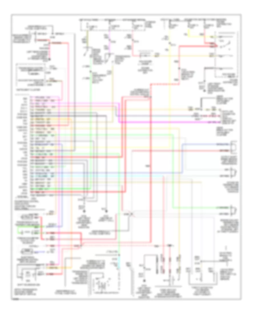
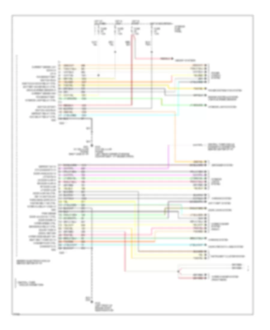
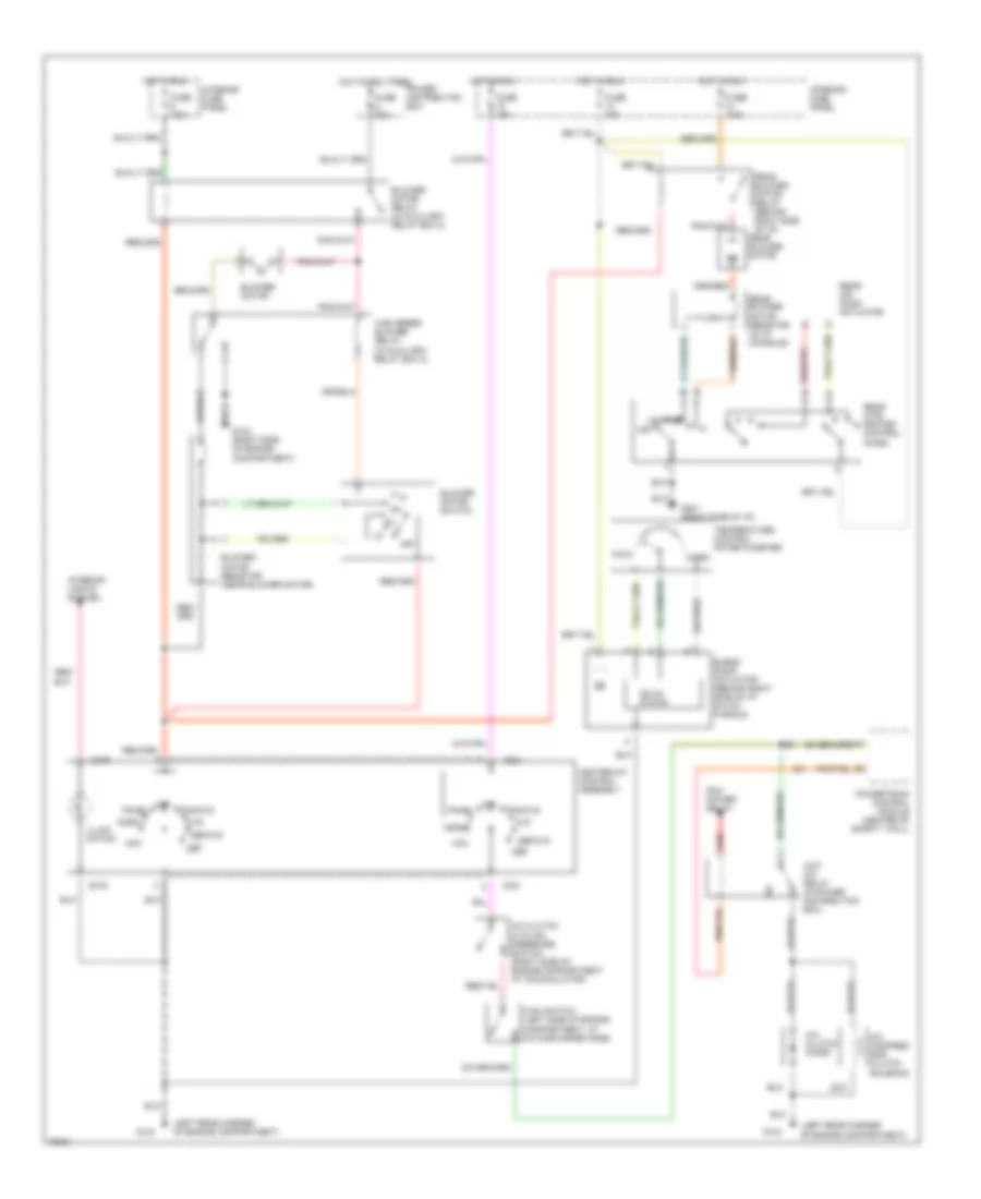
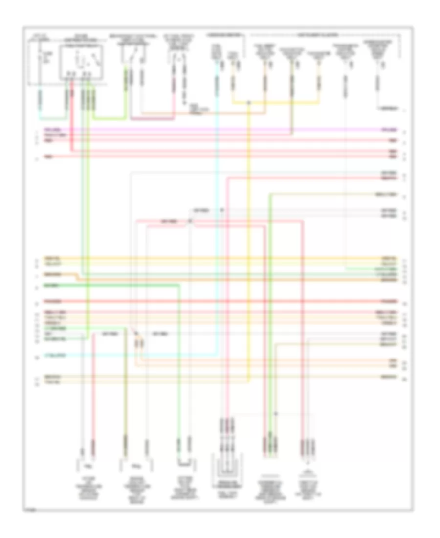
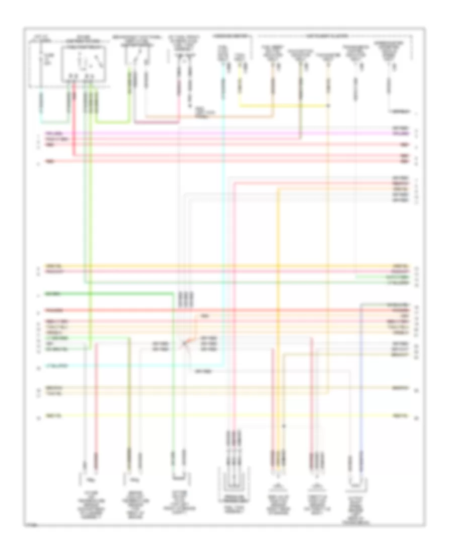
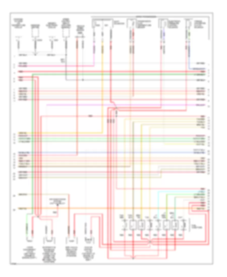
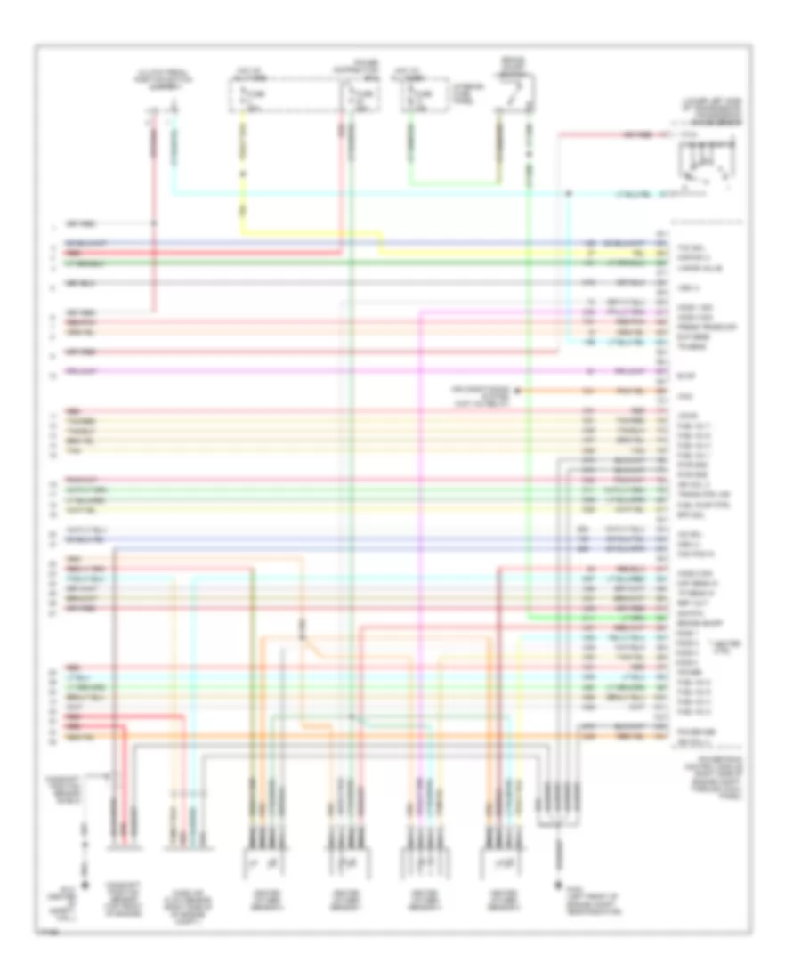
4.0L, 4R55E Электросхема коробки передач АКПП для Ford Explorer 1996

4.0L, 4R55E Электросхема коробки передач АКПП для Ford Explorer 1996 - Список элементов:
- (135 mm from branch to fuel pump relay) s123
- (30 mm from branch to fuel injector 4) s124
- (405 mm from break out to for bmap sensor) s136
- (center of safety wall) g121
- (in break out for powertrain control module) s101
- (in break out to harness in-line connector, rear of engine compartment)
- (left front of engine compartment, near radiator) g100
- (left rear corner of engine compartment, at fender apron) g104
- (left side of automatic transmission) transmission range (tr) sensor
- (near break out for instrument cluster)
- (near break out to fuel injector 6)
- (near break out to fuel injector 6) s166
- (near break out to transmission connector)
- (power for heated oxygen sensors)
- 4r55e transmission (mounted under center of vehicle)
- 87a
- Boo
- Brake on/off (boo) switch (behind steering column)
- C202
- C286
- C288
- Ccs
- Coast clutch solenoid (ccs)
- Cse gnd
- Data link connector (dlc) (partial) (behind left side of instrument panel)
- Dlc
- Dlc (+)
- Dlc (-)
- Ect
- Electronic pressure control (epc) solenoid
- Engine coolant temperature (ect) sensor (mounted front of engine, left of throttle body)
- Epc
- Fuse 10a
- Fuse 13 30a
- Fuse 15a
- Fuse 19 25a
- Fuse 24 15a
- Fuse 4 20a
- Hot at all times
- Hot in run
- Hot in start or run
- Iat
- Instrument cluster
- Intake air temperature (iat) sensor (on intake manifold)
- Interior fuse panel
- Kapwr
- Maf
- Maf rtn
- Malfunction indicator lamp (mil) (check engine)
- Mass air flow (maf) sensor (right rear corner of engine compartment)
- Mil
- N d
- Od off
- Pcm power diode
- Pcm power relay
- Power distribution box
- Powertrain control module (pcm) (mounted through cowl panel)
- Pwr gnd
- Red
- S105
- S113
- S116
- S121
- S125
- S135
- S137
- S146 (100 mm from break out for throttle position sensor)
- S147 (near break out to auxiliary box 3)
- S157
- S162
- S167 (near break out to fuel injector 6)
- S169
- S205
- S206
- Shift solenoid (ss1)
- Shift solenoid (ss2)
- Shift solenoid (ss3)
- Sig rtn
- Ss1
- Ss2
- Ss3
- Tcc
- Tcil
- Tcs
- Tft
- Throttle position (tp) sensor (attached to throttle body)
- Torque converter clutch (tcc) solenoid
- Transmission control indicator lamp (tcil)
- Transmission control switch (tcs)
- Transmission fluid temperature (tft) sensor
- Tss
- Turbine shaft speed (tss) sensor
- Vehicle speed sensor (vss) (attached to transmission)
- Vpwr
- Vref
- Vss
- Vss (-)
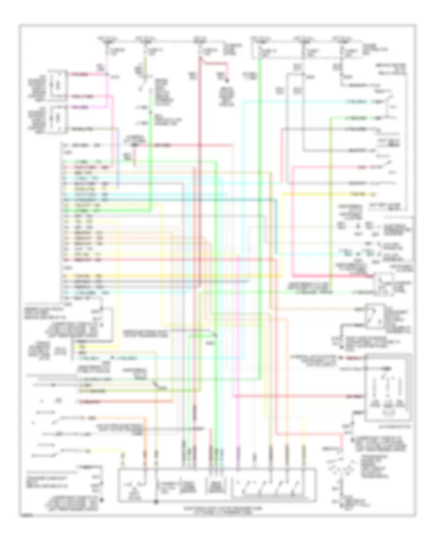
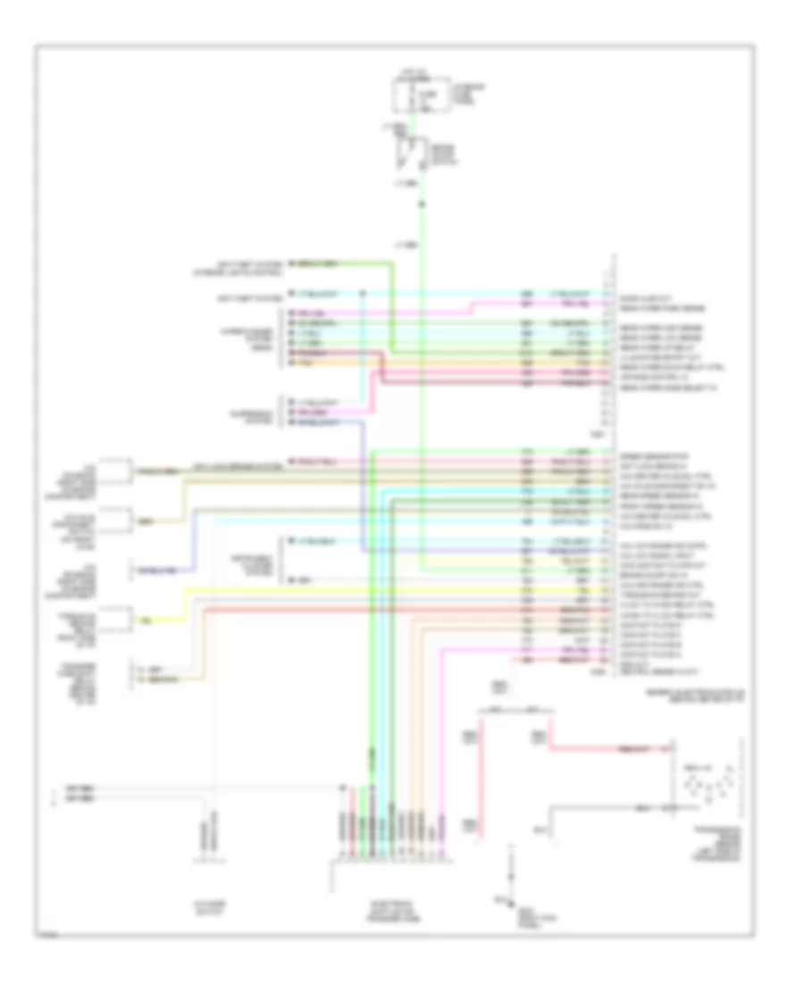
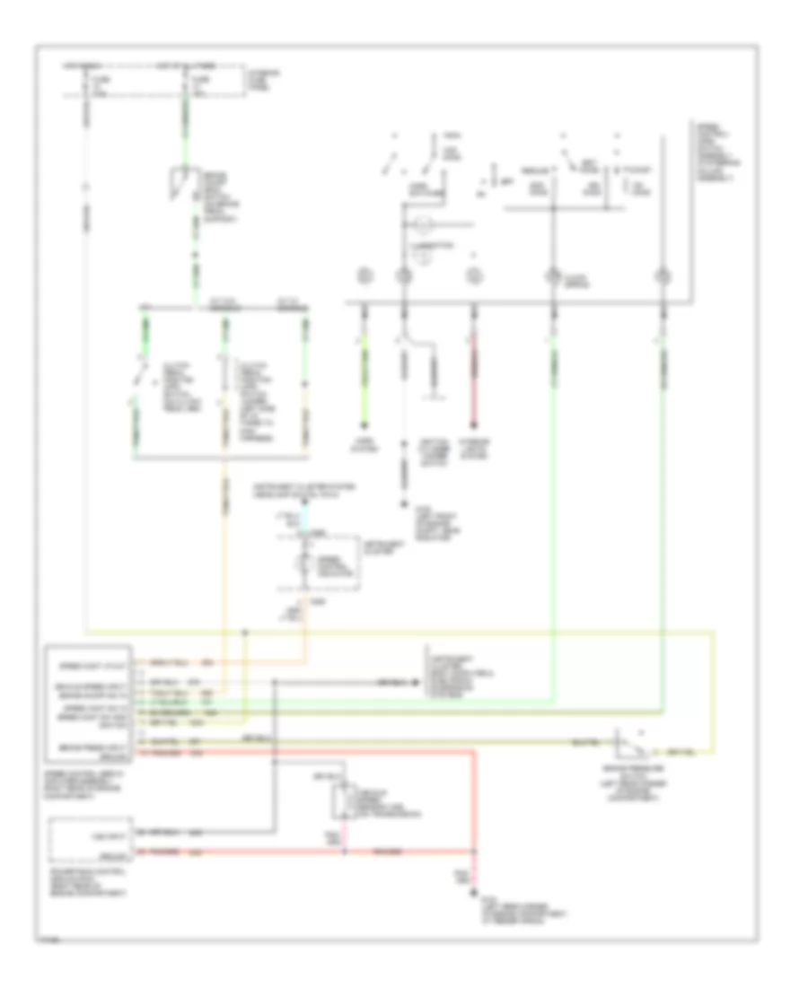
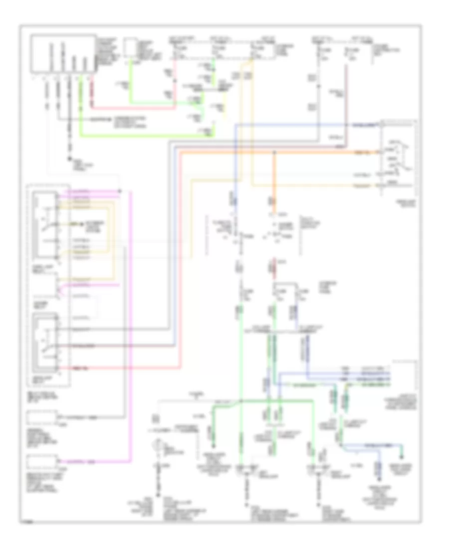
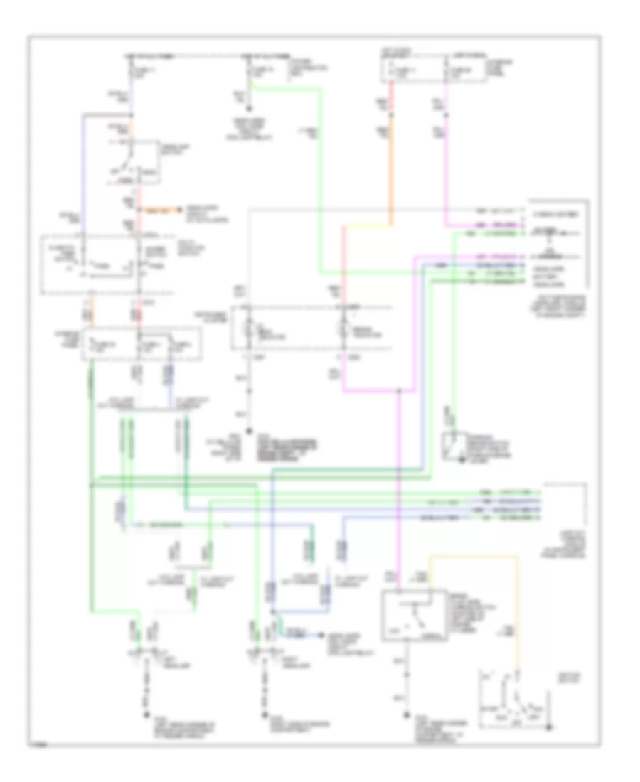
Электросхема раздатки для Ford Explorer 1996
Электросхема раздатки для Ford Explorer 1996 - Список элементов:
- (440 mm from electronic shift motor transfer case)
- (behind center of i/p) relay module
- (in break out to gem) s250
- (near break out for instrument cluster) s246
- (near break out to instrument cluster)
- (near break out to radio)
- (near electronic shift motor transfer case)
- (right side of engine compartment, attached to right quarter panel) g105
- (under right side of i/p) g201 g104 (left rear fender apron)
- (w/cellular phone) (w/o cellular phone)
- 1.1k ohms
- 3.9k ohms
- 4x2 solenoid (on right side of engine compart- ment)
- 4x4 disconnect switch (on front axle outboard of differential)
- 4x4 high range ind
- 4x4 low range ind
- 4x4 mode switch
- 4x4 solenoid (on right side of engine compart- ment)
- 87a
- Accy delay relay
- Battery saver relay
- Brake on/off (boo) switch (behind steering column)
- C280
- C282
- C283
- C286
- Electronic shift motor transfer case (attached to transfer case)
- Electronic speedometer/ odometer c287
- Front speed sensor
- Fuse 10a
- Fuse 13 15a
- Fuse 16 20a
- Fuse 26 10a
- Fuse 28 7.5a
- Fuse 5 30a
- Fuse 7 30a
- Generic electronic module (gem) (behind center of i/p)
- H2l
- Hot at all times
- Hot in start
- Instrument cluster
- Interior fuse panel
- Interior lights system (instrument illum- ination circuit)
- L2h
- Magnetic clutch coil
- Mode
- Ohms
- Pnk
- Power distribution box
- Rear speed sensor
- S108 (center of safety wall) g121
- S143
- S159
- S200
- S212 (for data link connector)
- S236
- S238
- S247
- S248
- S249
- S251
- S252
- S259 (near break out to relay module)
- Seats system (memory seat module)
- Shift motor
- Solid state
- Torque on demand (tod) relay (right side of i/p)
- Transfer case shift relay (behind center of i/p)
- Transmission range (tr) sensor (left side of automatic transmission)
5.0L
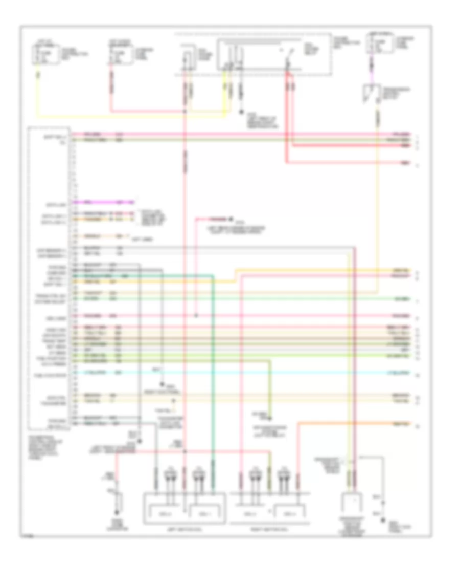
5.0L, 4R7OW Электросхема коробки передач АКПП для Ford Explorer 1996
5.0L, 4R7OW Электросхема коробки передач АКПП для Ford Explorer 1996 - Список элементов:
- (100 mm from break out for throttle position sensor)
- (30 mm from branch to fuel injector 4)
- (in break out for powertrain control module) s101
- (in break out to harness in line connector, rear of engine compartment)
- (left front of engine compartment, near radiator) g100
- (left rear corner of engine compartment, at fender apron) g104
- (near break out for instrument cluster)
- (near break out to fuel injector 6)
- (power for heated oxygen sensors)
- 4r70w transmission (mounted under center of vehicle)
- 87a
- Boo
- Brake on/off (boo) switch (behind steering column)
- C202
- C286
- C288
- Case gnd
- Data
- Data link connector (dlc) (partial) (behind left side of i/p)
- Dlc (+)
- Dlc (-)
- Ect
- Electronic pressure control (epc) solenoid
- Engine coolant temperature (ect) sensor (mounted front of engine, left of throttle body)
- Epc
- Fuse 13 15a
- Fuse 13 30a
- Fuse 19 25a
- Fuse 24 20a
- Fuse 26 10a
- Fuse 4 20a
- G100 (left front of engine compartment, near radiator)
- G121 (center of safety wall)
- Hot at all times
- Hot in run
- Hot in start or run
- Iat
- Instrument cluster
- Intake air temperature (iat) sensor (on intake manifold)
- Interior fuse panel
- Kapwr
- Maf
- Maf rtn
- Malfunction indicator lamp (mil) (check engine)
- Mass air flow (maf) sensor (right rear corner of engine compartment)
- Mil
- N d
- Od off
- Oss
- Output shaft speed sensor (left rear of transmission)
- Pcm power diode
- Pcm power relay
- Power distribution box
- Powertrain control module (pcm) (mounted through cowl panel)
- Pwr gnd
- Red
- S105
- S113
- S116
- S123 (135 mm from branch to fuel pump relay)
- S124
- S135
- S137
- S146
- S147 (near break out to auxiliary box 3)
- S157
- S162
- S166
- S167
- S169
- S205
- S206
- Shift solenoids (ss)
- Sig rtn
- Ss1
- Ss2
- Tcc
- Tcil
- Tcs
- Tft
- Throttle position (tp) sensor (attached to throttle body)
- Torque converter clutch (tcc) solenoid
- Transmission control indicator lamp (tcil)
- Transmission control switch (tcs)
- Transmission fluid temperature sensor
- Transmission range (tr) sensor (left side of automatic transmission)
- Vehicle speed sensor (vss) (attached to transmission)
- Vpwr
- Vref
- Vss
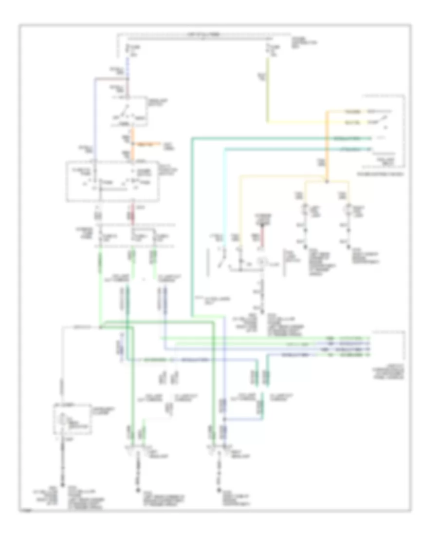
Электросхема раздатки для Ford Explorer 1996
Электросхема раздатки для Ford Explorer 1996 - Список элементов:
- (440 mm from electronic shift motor transfer case)
- (behind center of i/p) relay module
- (in break out to gem) s250
- (near break out for instrument cluster) s246
- (near break out to instrument cluster)
- (near break out to radio)
- (near electronic shift motor transfer case)
- (right side of engine compartment, attached to right quarter panel) g105
- (under right side of i/p) g201 g104 (left rear fender apron)
- (w/cellular phone) (w/o cellular phone)
- 1.1k ohms
- 3.9k ohms
- 4x2 solenoid (on right side of engine compart- ment)
- 4x4 disconnect switch (on front axle outboard of differential)
- 4x4 high range ind
- 4x4 low range ind
- 4x4 mode switch
- 4x4 solenoid (on right side of engine compart- ment)
- 87a
- Accy delay relay
- Battery saver relay
- Brake on/off (boo) switch (behind steering column)
- C280
- C282
- C283
- C286
- Electronic shift motor transfer case (attached to transfer case)
- Electronic speedometer/ odometer c287
- Front speed sensor
- Fuse 10a
- Fuse 13 15a
- Fuse 16 20a
- Fuse 26 10a
- Fuse 28 7.5a
- Fuse 5 30a
- Fuse 7 30a
- Generic electronic module (gem) (behind center of i/p)
- H2l
- Hot at all times
- Hot in start
- Instrument cluster
- Interior fuse panel
- Interior lights system (instrument illum- ination circuit)
- L2h
- Magnetic clutch coil
- Mode
- Ohms
- Pnk
- Power distribution box
- Rear speed sensor
- S108 (center of safety wall) g121
- S143
- S159
- S200
- S212 (for data link connector)
- S236
- S238
- S247
- S248
- S249
- S251
- S252
- S259 (near break out to relay module)
- Seats system (memory seat module)
- Shift motor
- Solid state
- Torque on demand (tod) relay (right side of i/p)
- Transfer case shift relay (behind center of i/p)
- Transmission range (tr) sensor (left side of automatic transmission)
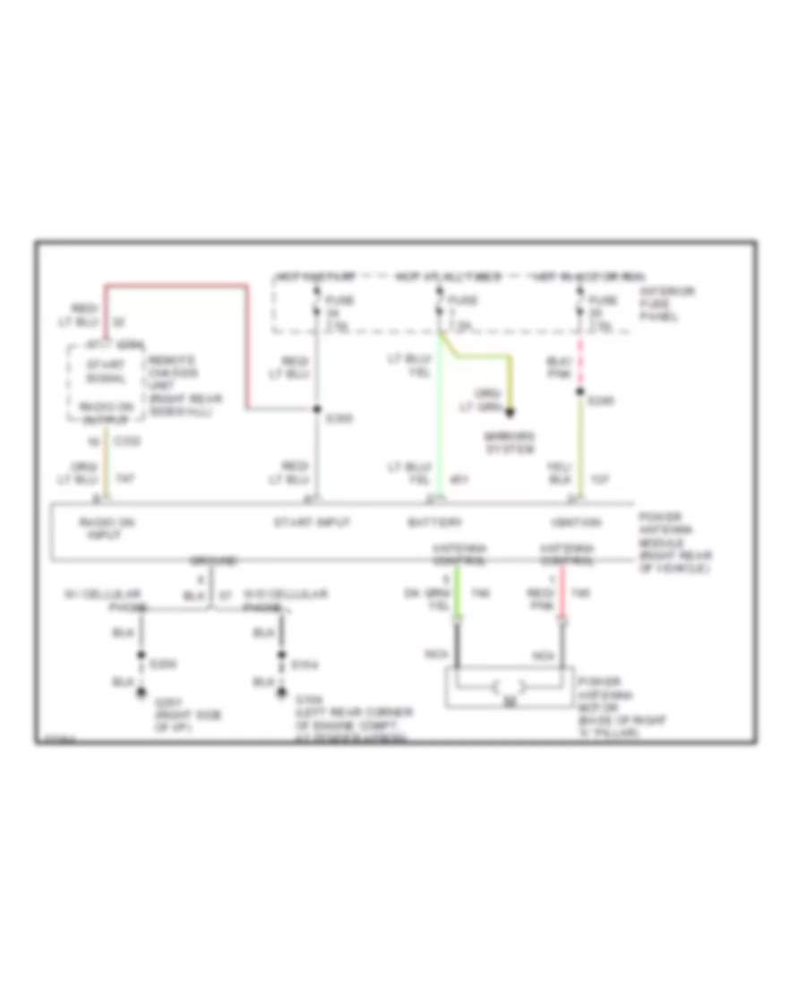
АНТЕННА ПИТАНИЯ
Электросхема антенны для Ford Explorer 1996
Электросхема антенны для Ford Explorer 1996 - Список элементов:
- Antenna control
- Battery
- C332
- C364
- Fuse 7.5a
- G104 (left rear corner of engine compt, at fender apron)
- G201 (right side of i/p)
- Ground
- Hot at all times
- Hot in acc or run
- Hot in start
- Ignition
- Interior fuse panel
- Mirrors system
- Nca
- Phone
- Power antenna module (right rear of vehicle)
- Power antenna motor (base of right "a" pillar)
- Radio on input
- Radio on output
- Red/ pnk
- Remote chassis unit (right rear sidewall)
- S154
- S200
- S245
- S355
- Start input
- Start signal
- W/ cellular
- W/o cellular phone
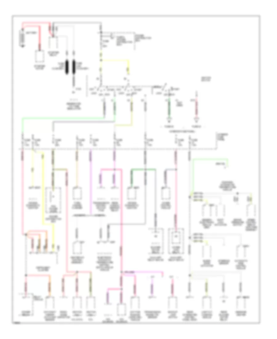
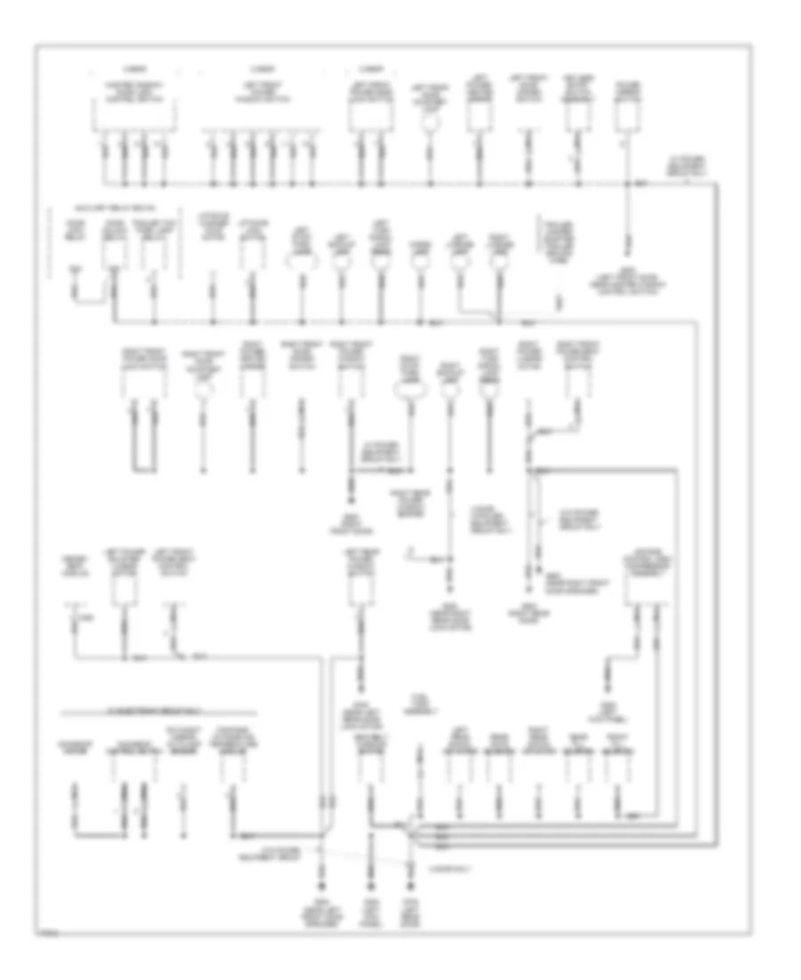
БЛОК ПРЕДОХРАНИТЕЛЕЙ И РЕЛЕ
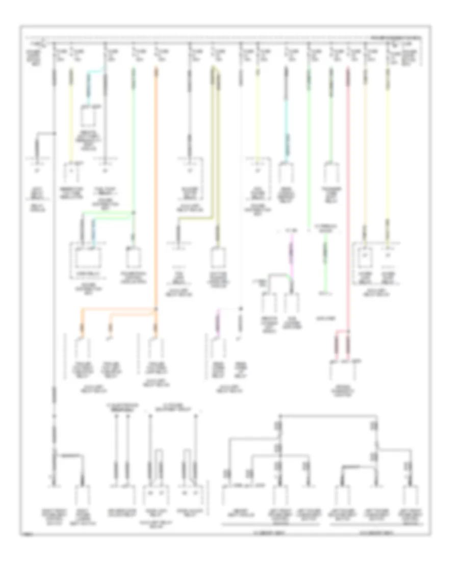
Электросхема блока предохранителей и реле (1 из 5) для Ford Explorer 1996
Электросхема блока предохранителей и реле (1 из 5) для Ford Explorer 1996 - Список элементов:
- (interior fuse panel)
- 4.0l & 5.0l
- 4wabs control module
- 4wabs main relay
- 4x2 solenoid
- 4x4 solenoid
- 5.0l
- A/t
- A1 (not used)
- Acc
- Air bag diagnostic monitor
- Automatic ride control module
- Auxiliary relay box #1
- Auxiliary relay box #2
- Backup lamp switch
- Battery
- Blend door actuator
- Blower motor relay
- Brake pressure switch
- C122
- C2001
- C2008
- C231
- C232
- C233
- C283
- C286
- C287
- C288
- C297
- Compass/ outside air temperature module
- Day/night mirror/ autolamp sensor
- Daytime running lamps (drl) module
- Dimmer relay
- Electronic automatic temperature control (eatc) module module
- Fuse 10a
- Fuse 15a
- Fuse 20
- Fuse 24
- Fuse 25a
- Fuse 5 (power distribution box)
- Fuse 60a
- Fuse 7.5a
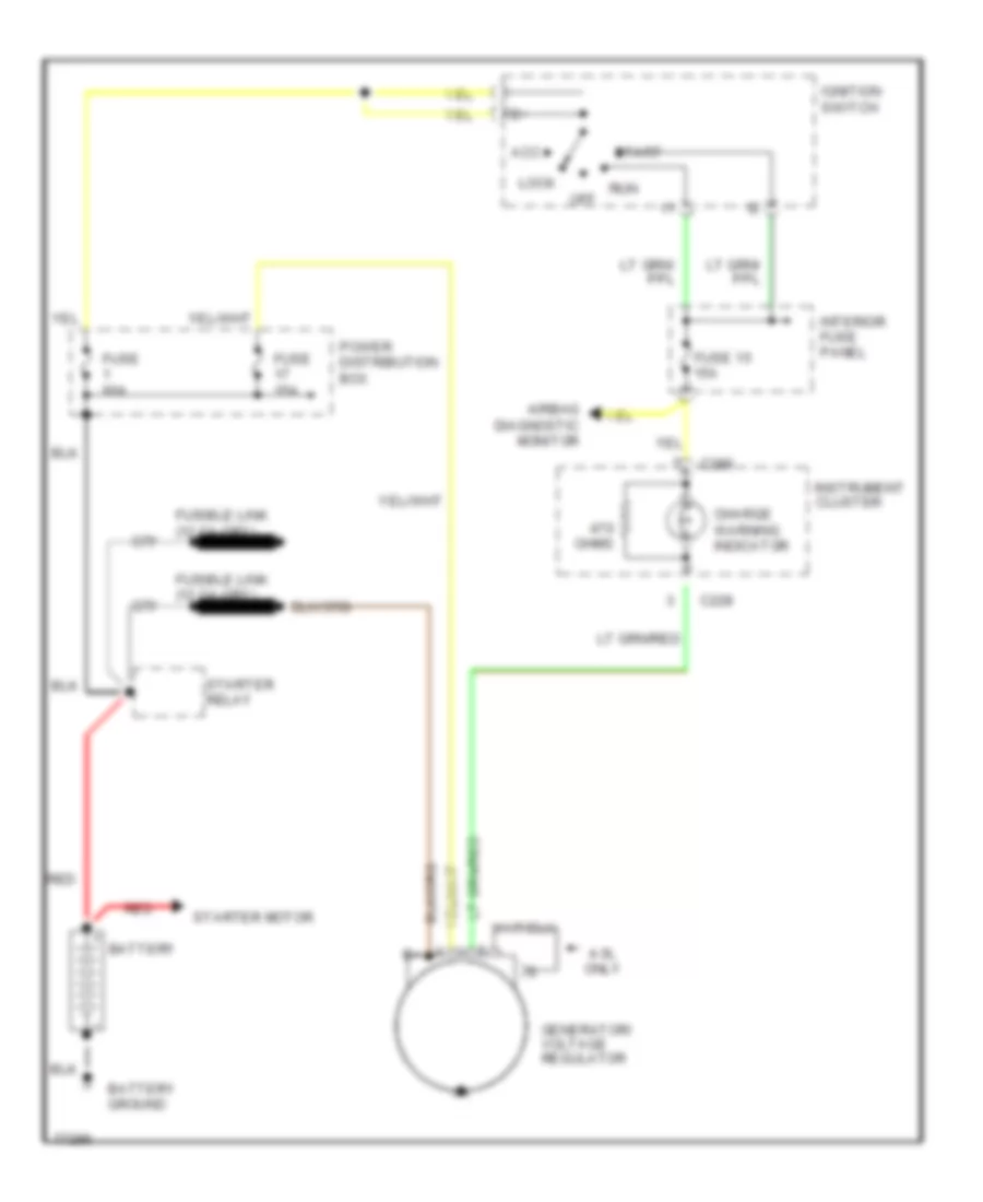
- Generator/ voltage regulator
- Generic electronic module (gem)
- Heater-a/c control assembly
- Ignition coil
- Ignition switch
- Instrument cluster
- Interior fuse panel
- Lamp out warning module
- Lock
- M/t
- Message center
- Off
- Pcm power diode
- Power distribution box
- Radio noise capacitor
- Rear blower motor relay
- Rear integrated control panel (ricp)
- Rear window defrost relay
- Red
- Relay module
- Run
- Shift lock actuator
- Speed control servo/ amplifier assembly
- Start
- Starter motor
- Starter relay
- Steering sensor
- Transmission control switch (tcs)
- Transmission range (tr) sensor
- Turn/ hazard flasher
- W/ eatc
- W/o eatc
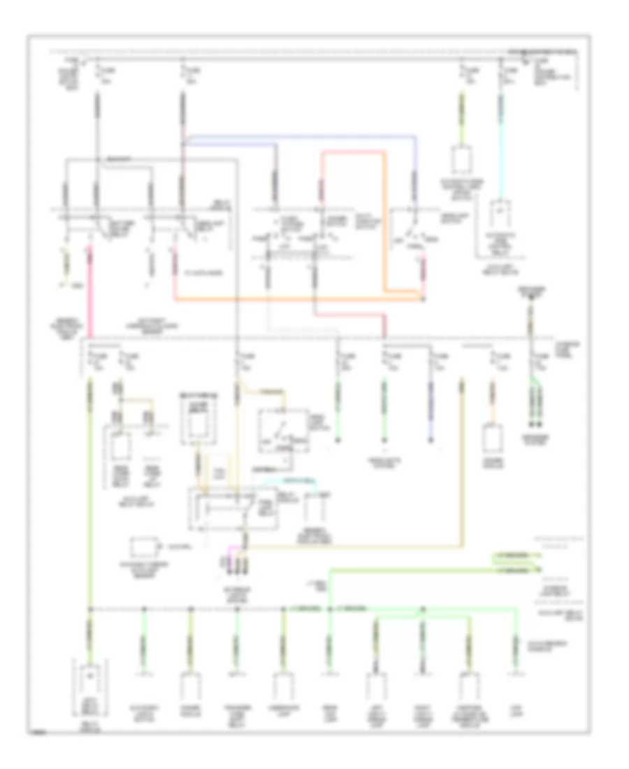
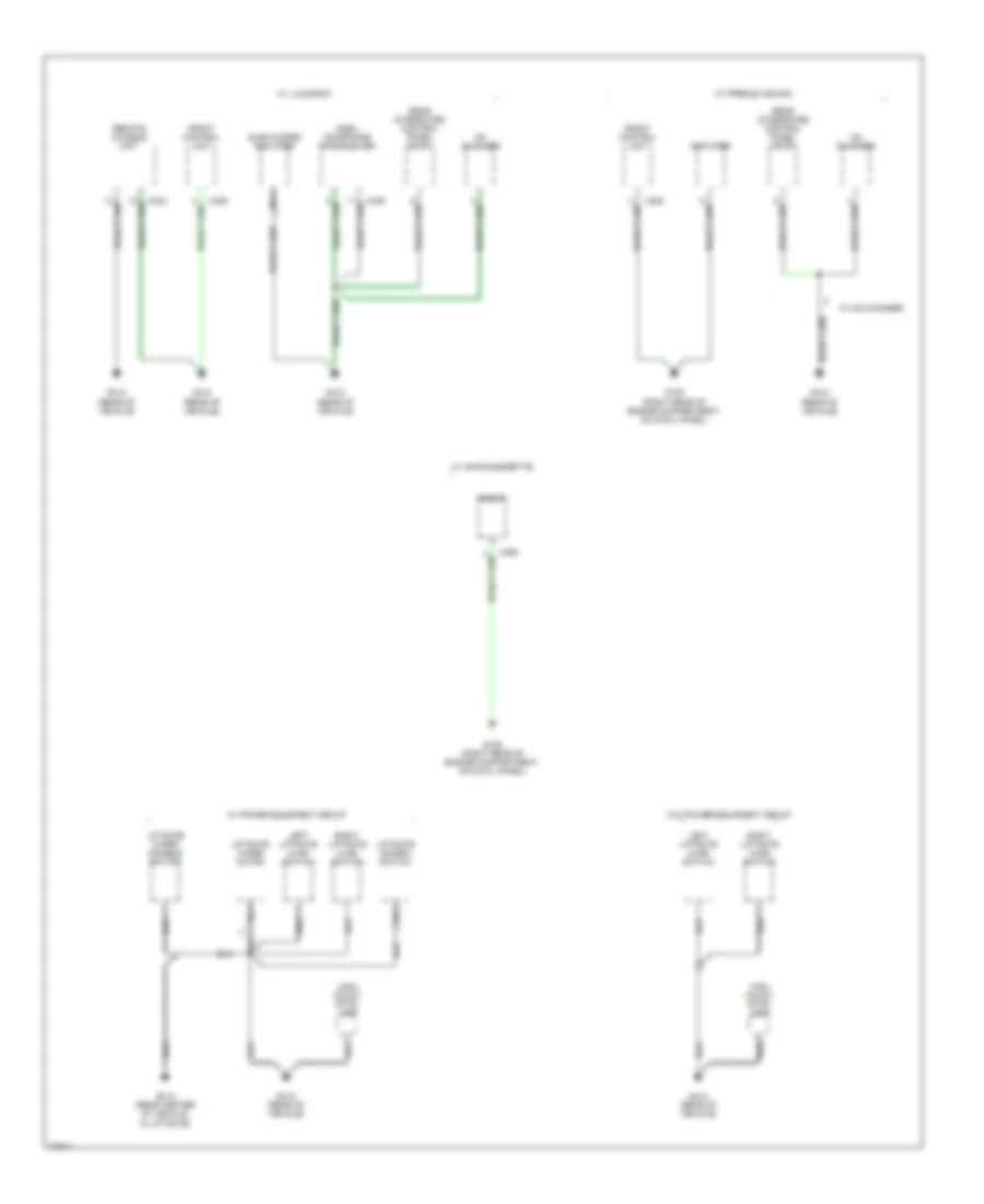
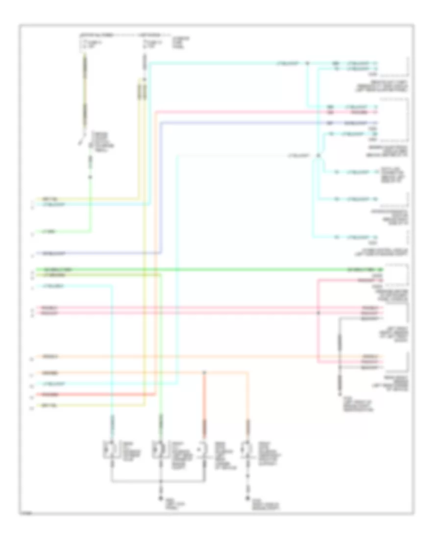
Электросхема блока предохранителей и реле (2 из 5) для Ford Explorer 1996
Электросхема блока предохранителей и реле (2 из 5) для Ford Explorer 1996 - Список элементов:
- 4wabs main relay
- 4wabs pump relay
- Accy delay relay
- Air bag diagnostic monitor
- Amplifier
- Auxiliary relay box #1
- Auxiliary relay box #2
- Auxiliary relay box #4
- Blower motor relay
- C121
- C232
- C335
- C338
- C350
- Daytime running lamps (drl) module
- Door lock relay
- Door unlock relay
- Driver's door unlock relay
- Fog lamp relay
- Fuel pump relay
- Fuse (power distri- bution box)
- Fuse 10a
- Fuse 15a
- Fuse 20a
- Fuse 30a
- Fuse 50a
- Fuse a (power distri- bution box)
- Generator/ voltage regulator
- Horn relay
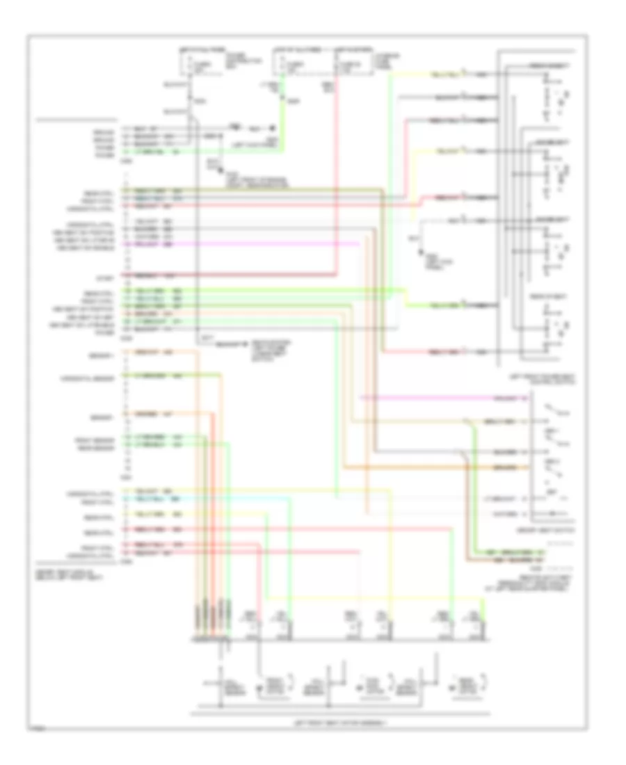
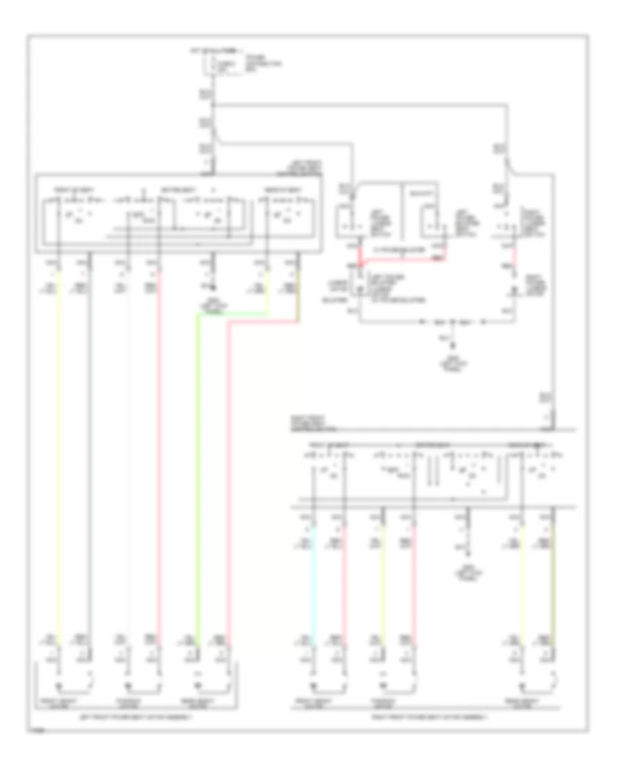
- Left front power seat control switch
- Left power bolster seat switch
- Left power lumbar seat switch
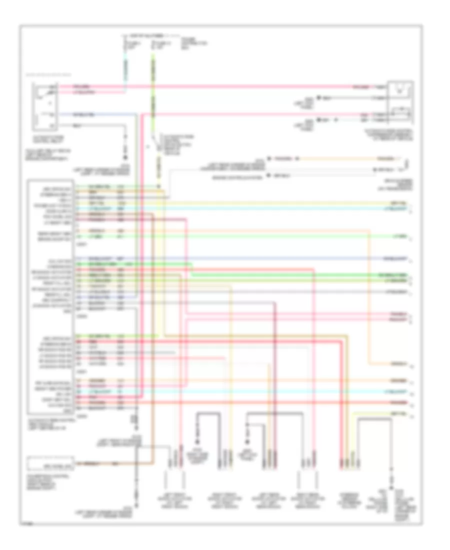
- Memory seat module
- Nca
- Pcm power relay
- Power distribution box
- Powertrain control module (pcm)
- Rear window defrost relay
- Rear wiper down relay
- Rear wiper up relay
- Relay module
- Remote anti-theft personality (rap) module
- Remote chassis unit (radio)
- Right front power seat control switch
- Right power lumbar seat switch
- Sub woofer amplifier
- Trailer tow left turn/stop relay
- Trailer tow park lamp relay
- Trailer tow right turn/stop relay
- Transfer case shift relay
- W/ electronics group only
- W/ jbl
- W/ memory seat
- W/ power equipment group
- W/ premium sound
- W/o memory seat
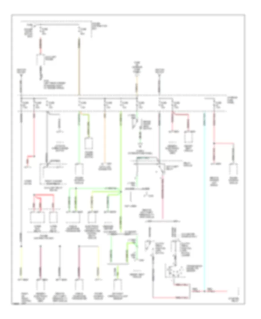
Электросхема блока предохранителей и реле (3 из 5) для Ford Explorer 1996
Электросхема блока предохранителей и реле (3 из 5) для Ford Explorer 1996 - Список элементов:
- Accy delay relay
- Automatic ride control (arc) off/on switch
- Automatic ride control relay
- Auxiliary relay box #1
- Auxiliary relay box #3
- Auxiliary relay box #4
- Battery saver relay
- C280
- C283
- Compass/ outside air temperature module
- Day/night mirror/ autolamp sensor
- Day/night mirror/autolamps sensor
- Defogger system
- Dimmer module
- Dimmer relay
- Dimmer switch
- Exterior lights system
- Flash- to-pass switch
- Fuse (power distribution box)
- Fuse 10a
- Fuse 15a
- Fuse 1oa
- Fuse 20a
- Fuse 30a
- Fuse 50a
- Fuse 7.5a
- Fuse d (power distri- bution box)
- Generic electronic module (gem)
- Glove box lamp & switch
- Head
- Head- lamp switch
- Headlamp relay
- Headlamp switch
- Headlights system
- Interior fuse panel
- Interior lamp relay
- Left vanity mirror lamp
- Low
- Map lamp
- Multi- function switch
- Nca
- Off
- Park
- Park lamp relay
- Pass
- Pnk
- Power distribution box
- Rear map lamp
- Rear wiper down relay
- Rear wiper up relay
- Relay module
- Right vanity mirror lamp
- Transfer case shift relay
- Underhood lamp
- W/ autolamps
- W/o overhead console
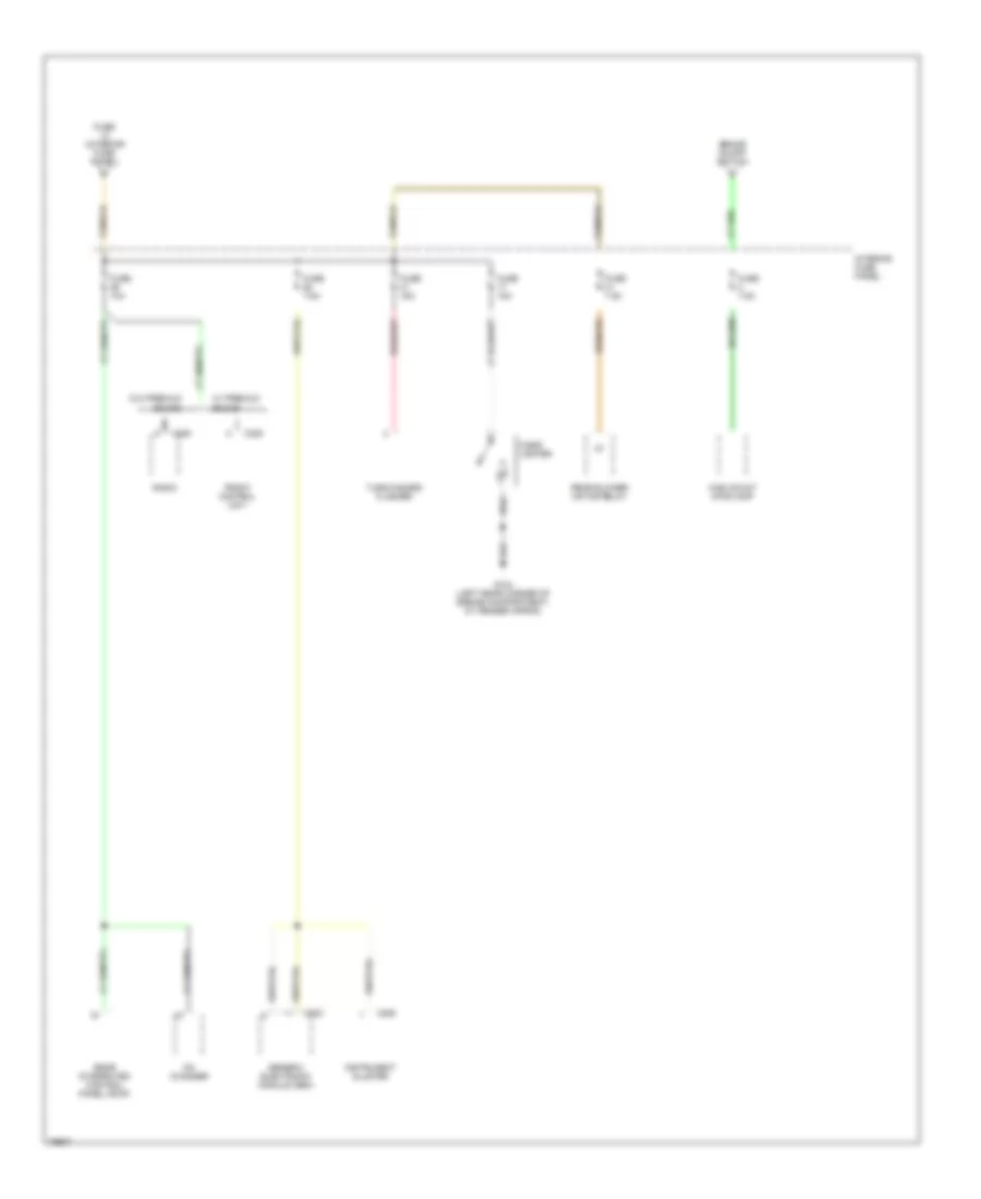
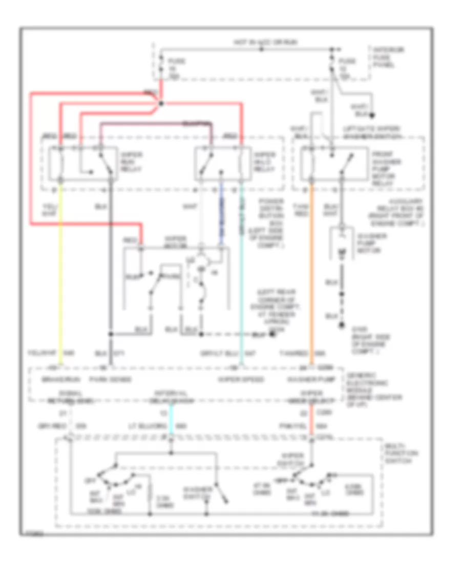
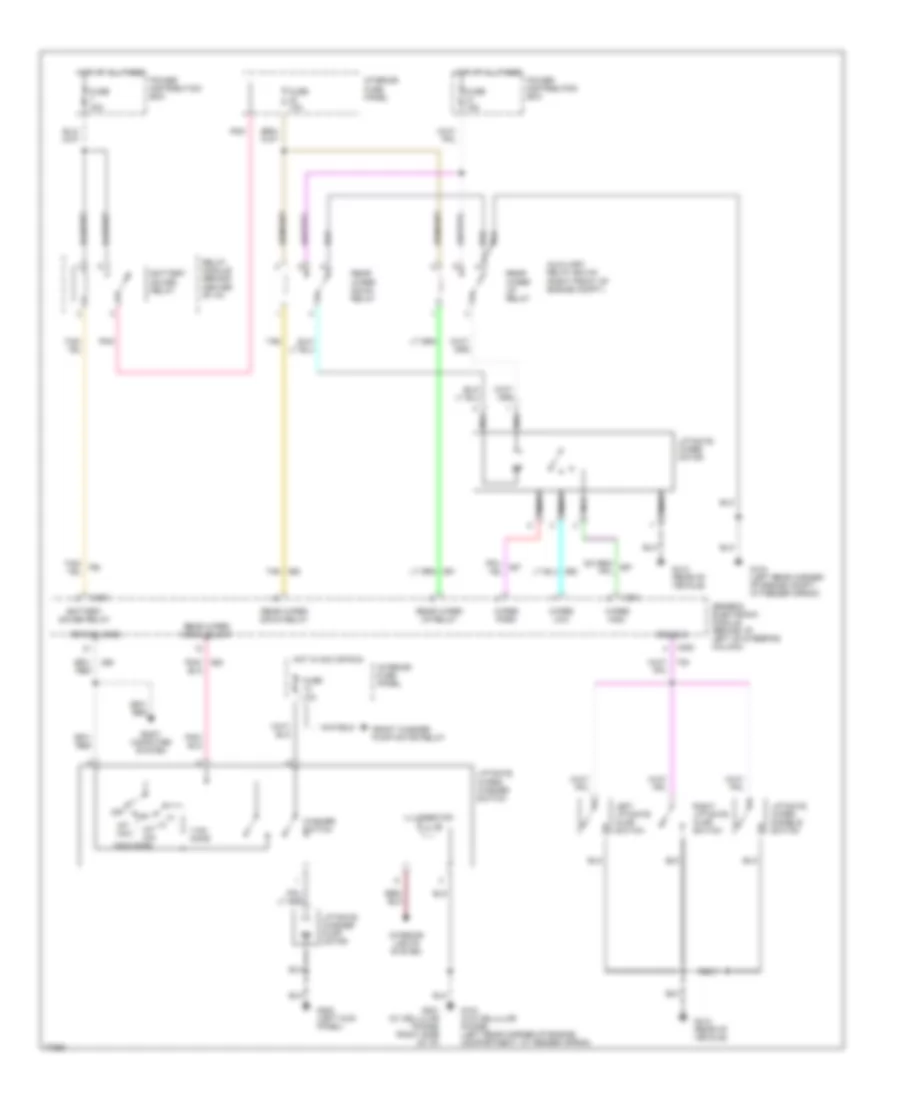
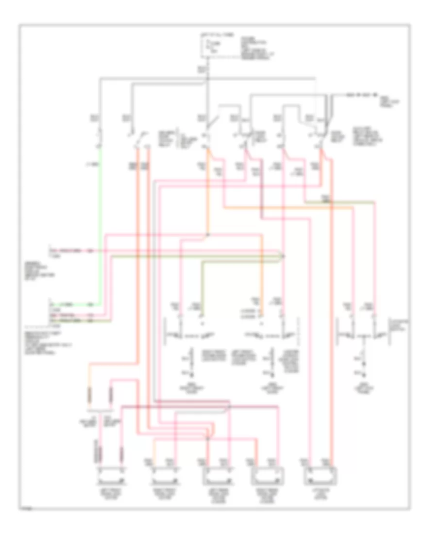
Электросхема блока предохранителей и реле (4 из 5) для Ford Explorer 1996
Электросхема блока предохранителей и реле (4 из 5) для Ford Explorer 1996 - Список элементов:
- (not used)
- A/t
- Anti-theft relay
- Auxiliary power
- Auxiliary relay box #2
- Brake on/off (boo) switch
- C2009
- C228
- C283
- C291
- C297
- C335
- C336
- C338
- C350
- C364
- C435
- Clutch pedal position (cpp) switch
- Clutch pedal position (cpp) switch jumper
- Data link connector
- Day/night mirror/autolamp sensor
- Electronic automatic temperature control (eatc) module
- Front washer pump relay
- Fuse (interior fuse panel)
- Fuse 10a
- Fuse 15a
- Fuse 2 (interior fuse panel)
- Fuse 30a
- Fuse 60a
- Fuse 7.5a
- Fuse e (power distri- bution box)
- G104 (left rear corner of engine compt. at fender apron)
- Generic electronic module (gem)
- Ignition switch
- Interior fuse panel
- Liftgate wiper/washer switch
- M/t
- Memory seat module
- Message center
- Mobile telephone transceiver
- Pnk
- Power antenna module
- Power distribution box
- Power mirror switch
- Radio or front control unit
- Red
- Relay module
- Remote anti-theft personality (rap) module
- Remote anti-theft/ personality (rap) module
- Remote chassis unit (radio)
- Starter relay
- Transmission range (tr) sensor
- W/ memory seat
- W/ rap
- W/o center console only
- W/o memory seat
- W/o rap
- Wiper hi-lo relay
- Wiper motor
- Wiper run relay
Электросхема блока предохранителей и реле (5 из 5) для Ford Explorer 1996
Электросхема блока предохранителей и реле (5 из 5) для Ford Explorer 1996 - Список элементов:
- Brake on/off switch
- C228
- C283
- C288
- Cd changer
- Cigar lighter
- Front control unit
- Fuse (interior fuse panel)
- Fuse 10a
- Fuse 15a
- Fuse 7.5a
- G104 (left rear corner of engine compartment, at fender apron)
- Generic electronic module (gem)
- High mount stoplamp
- Instrument cluster
- Interior fuse panel
- Radio
- Rear blower motor relay
- Rear integrated control panel (ricp)
- Turn/hazard flasher
- W/ premium sound
- W/o premium sound
БЛОК УПРАВЛЕНИЯ КУЗОВОМ
Электросхема блока управления кузовом (1 из 2) для Ford Explorer 1996
Электросхема блока управления кузовом (1 из 2) для Ford Explorer 1996 - Список элементов:
- (front)
- (front-rear)
- * central timer
- Acc delay relay ctrl
- Anti-theft system
- Battery saver relay ctrl
- Brake/run relay ctrl
- C280
- C283
- Central timer module diagnostic connector (behind center of i/p)
- Computer data lines system
- Ctm diagnostic in
- Current sense high
- Current sense low
- Defogger system
- Defrost relay ctrl
- Defrost sw in
- Diagnostic in
- Door ajar ind ctrl
- Door disarm in
- Door handle sw in
- Door locks system
- Door unlock rly ctrl
- Down in
- Engine controls system (vehicle speed sensor)
- Fasten belt ind ctrl
- Fuse 7.5a
- G100 (left front of engine compt, near radiator)
- G104 (w/o cellular phone) (left rear corner of engine compartment, at fender apron)
- G201 (w/ cellular phone) (right side of i/p)
- Generic electronic module (behind center of i/p)
- Gnd
- Hot at all times
- Hot in acc or run
- Hot in run
- Hot in start
- Ignition (acc/run)
- Ignition (run)
- Ignition (start)
- Instrument cluster system
- Interior fuse panel
- Interior lamp relay ctrl
- Interior lights system
- Interval/delay wash in
- Key in ignition sw
- Lf door ajar
- Liftgate in
- Lr door ajar in
- Memory systems
- Module connectors
- One-touch down relay ctrl
- Park sense
- Park/headlamps on in
- Power distribution system
- Power window system
- Power-battery
- Power-battery
- Rf door ajar
- Rr door ajar in
- Seat belt warn sw in
- Signal return
- Sound tone in
- Tan/red
- Up in
- Vehicle speed sensor in
- Warning system
- Washer pump ctrl
- Wiper mode select sw
- Wiper speed ctrl
- Wiper/washer system
Электросхема блока управления кузовом (2 из 2) для Ford Explorer 1996
Электросхема блока управления кузовом (2 из 2) для Ford Explorer 1996 - Список элементов:
- (rear)
- 4-high to 4-low relay ctrl
- 4-low to 4-high relay ctrl
- 4wd contact plate out
- 4x2 center axle sol ctrl
- 4x2 solenoid (right side of engine compartment)
- 4x4 axle disconnect sw in
- 4x4 axle disconnect switch (on front axle)
- 4x4 center axle sol ctrl
- 4x4 high range ind ctrl
- 4x4 low range ind cntrl
- 4x4 low signal input
- 4x4 mode sw in
- 4x4 mode switch
- 4x4 solenoid (right side of engine compartment)
- A/t
- Air ride control in
- Anti-lock brake in
- Anti-lock brakes system
- Anti-theft system
- Anti-theft system (interior lights control)
- Brake on/off sw in
- Brake on/off switch
- C281
- C282
- Contact plate a
- Contact plate b
- Contact plate c
- Contact plate d
- Door ajar out
- Electronic shift motor transfer case
- Front speed sensor in
- Fuse 15a
- G203 (right kick panel)
- Generic electronic module (behind center of i/p)
- Gnd (m/t) neutral sense in (a/t)
- Hot at all times
- Illuminated entry out
- Instrument cluster system
- Interior fuse panel
- M/t
- Rear speed sensor in
- Rear wiper down relay ctrl
- Rear wiper high sense
- Rear wiper low sense
- Rear wiper mode select in
- Rear wiper park sense
- Rear wiper up relay
- Speed sensor pwr
- Suspension system
- Tan
- Torque on demand relay (right side of i/p)
- Torque-on-demand out
- Transfer case shift relay (behind center of i/p)
- Transmission range sensor (left side of transmission)
- Wiper/washer system
БЛОКИРОВКИ СЕЛЕКТОРА СТОЯНОЧНЫЙ ТОРМОЗ
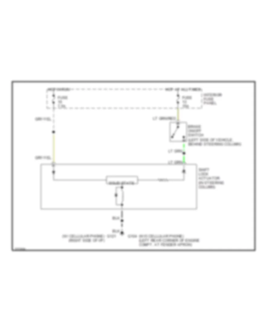
Электросхема блокировки селектора для Ford Explorer 1996
Электросхема блокировки селектора для Ford Explorer 1996 - Список элементов:
- (left side of vehicle, behind steering column)
- (w/ cellular phone) (right side of i/p)
- (w/o cellular phone) (left rear corner of engine compt, at fender apron)
- Brake on/off switch
- Fuse 15a
- Fuse 7.5a
- G104
- G121
- Hot at all times
- Hot in run
- Interior fuse panel
- Shift lock actuator (in steering column)
- Solid state
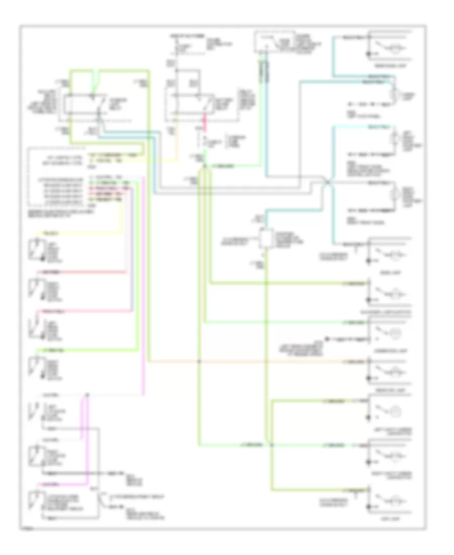
ВНЕШНЕЕ ОСВЕЩЕНИЕ
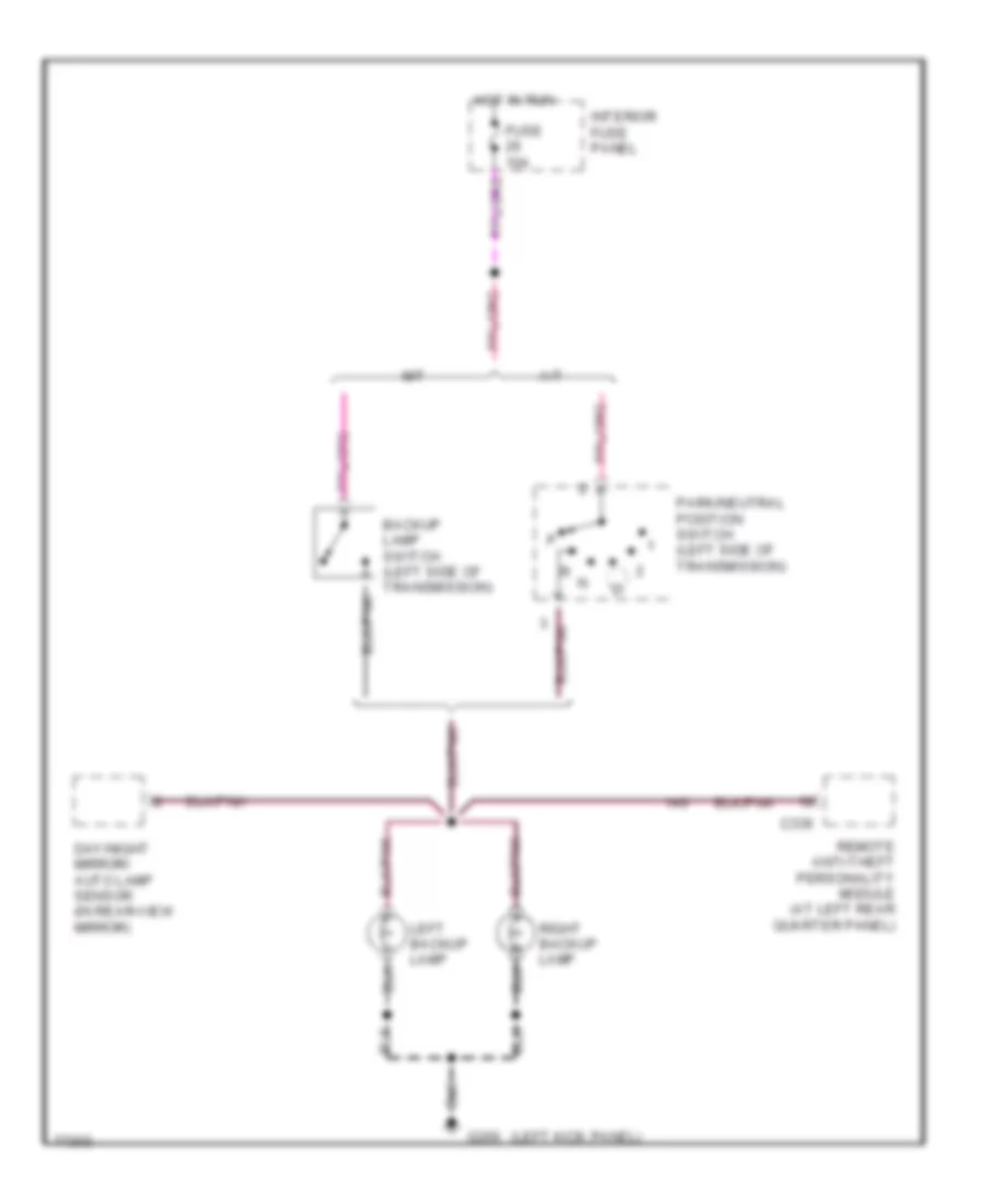
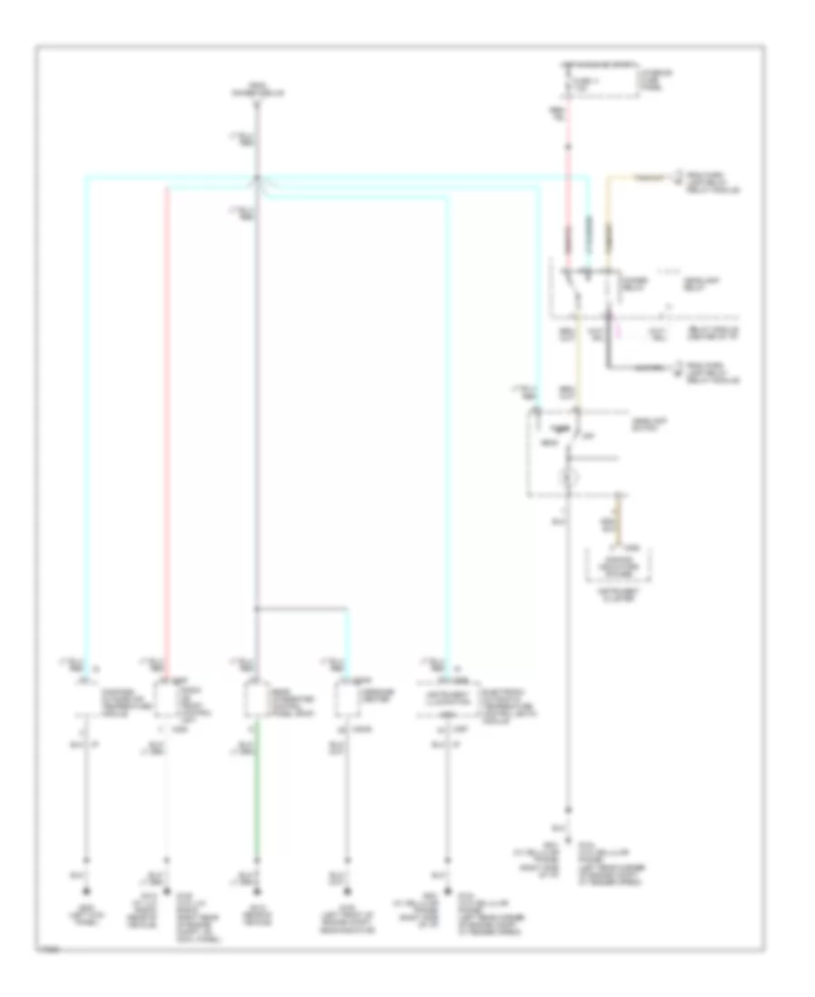
Электросхема заднего хода для Ford Explorer 1996
Электросхема заднего хода для Ford Explorer 1996 - Список элементов:
- (left kick panel)
- A/t
- Backup lamp switch (left side of transmission)
- C336
- Day/night mirror/ auto lamp sensor (in rear-view mirror)
- Fuse 10a
- G200
- Hot in run
- Interior fuse panel
- Left backup lamp
- M/t
- Park/neutral position switch (left side of transmission)
- Remote anti-theft personality module (at left rear quarter panel)
- Right backup lamp
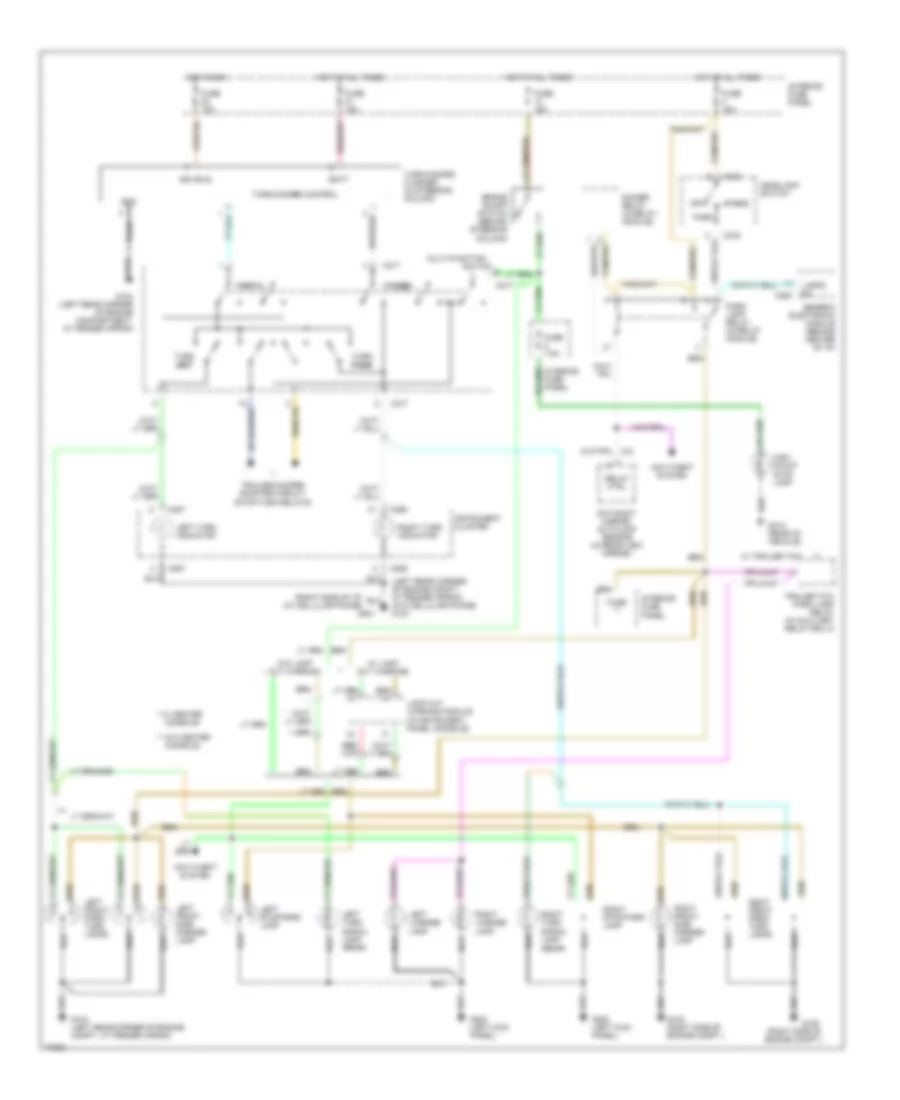
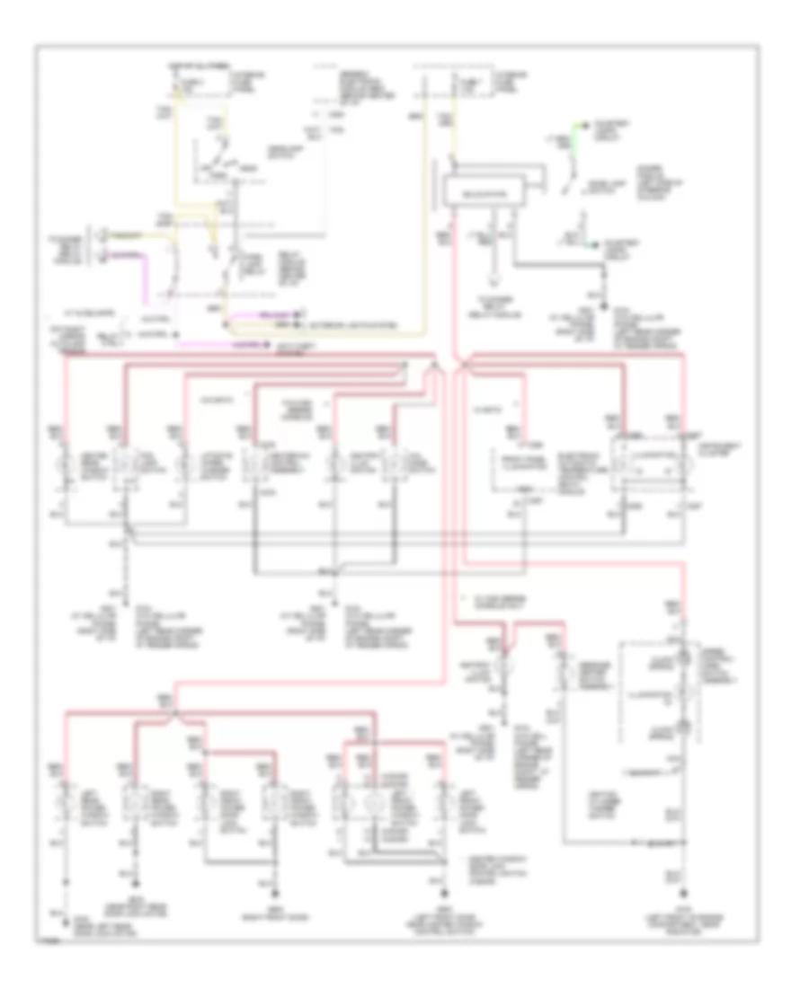
Электросхема внешнего освещения для Ford Explorer 1996
Электросхема внешнего освещения для Ford Explorer 1996 - Список элементов:
- (left rear corner of engine compt., at fender apron) (w/o cellular phone) g104
- (rear)
- (right side of engine compt.)
- (right side of i/p) (w/ cellular phone)
- * w/ center
- ** w/o center
- Anti-theft system
- Batt
- Brake on/off switch (behind steering column)
- C216
- C217
- C280
- C286
- C287
- Console
- Day/night mirror/ autolamp sensor (in rear-view mirror)
- Dimmer relay (in relay module)
- Fuse
- Fuse 10a
- Fuse 15a
- Fuse 7.5a
- G104 (left rear corner of engine compartment, at fender apron)
- G104 (left rear corner of engine compt., at fender apron)
- G105
- G105 (right side of engine compt.)
- G200 (left kick panel)
- G201
- G412 (rear of vehicle)
- Generic electronic module (behind center of i/p)
- Gnd
- Hazard
- Head
- Headlamp switch
- High mount stop lamp
- Hot at all times
- Hot in run
- Ign (run)
- Instrument cluster
- Interior fuse panel
- Lamp out warning module (in instrument panel console)
- Lamps on
- Left front park/ turn lamps
- Left front side marker lamp
- Left license lamp
- Left stop/park lamp
- Left turn indicator
- Left turn signal lamp (rear)
- Multi-function
- Normal
- Off
- Park
- Park lamp relay (in relay module)
- Relay ctrl
- Right front park/ turn lamps
- Right front side marker lamp
- Right license lamp
- Right stop/park lamp
- Right turn indicator
- Right turn signal lamp
- Switch
- Trailer tow park lamp relay (in auxiliary relay box 4)
- Trailer/camper adapter circuit (stop/turn relays)
- Turn left
- Turn right
- Turn/hazard control
- Turn/hazard flasher (in steering column)
- W/ lamp out warning
- W/ trailer tow
- W/o lamp out warning
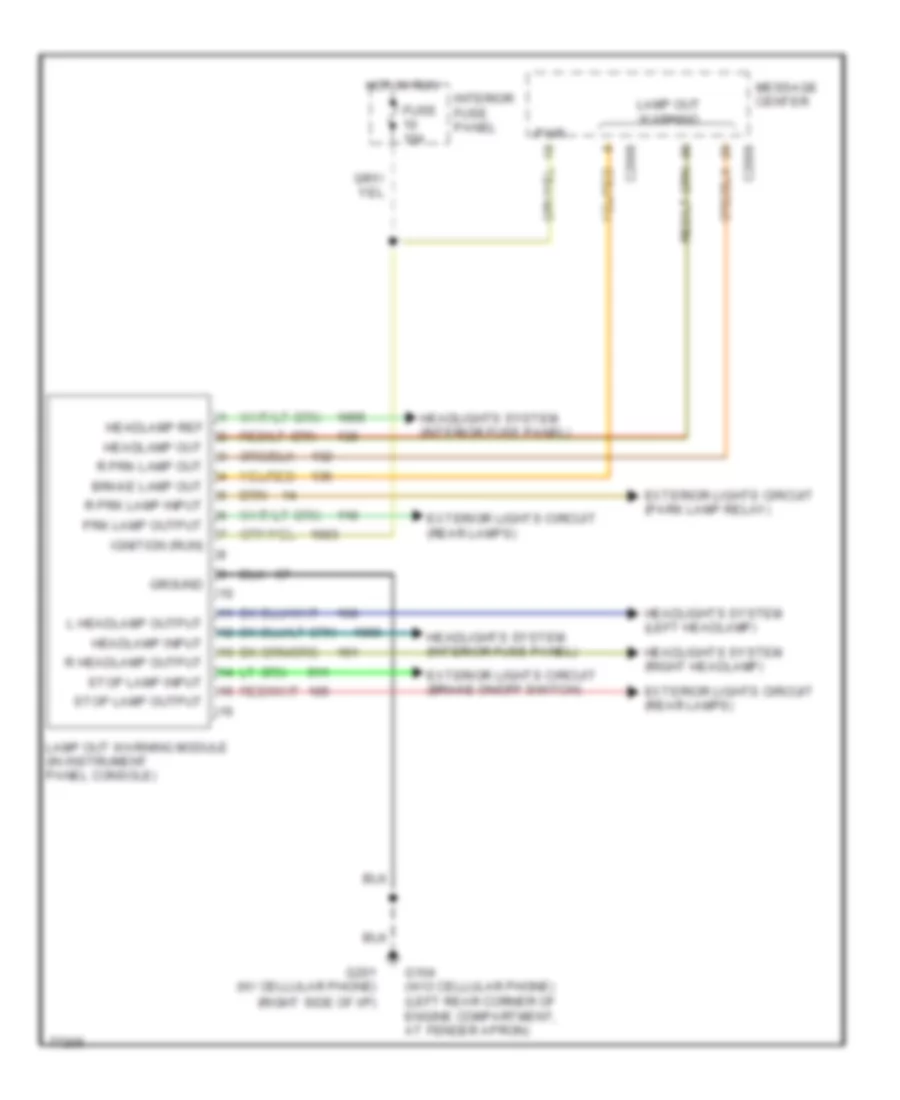
схема модуля отключения электричества лампы для Ford Explorer 1996
схема модуля отключения электричества лампы для Ford Explorer 1996 - Список элементов:
- Brake lamp out
- C2008
- C2009
- Exterior lights circuit (brake on/off switch)
- Exterior lights circuit (park lamp relay)
- Exterior lights circuit (rear lamps)
- Fuse 10a
- G104 (w/o cellular phone) (left rear corner of engine compartment, at fender apron)
- G201 (w/ cellular phone) (right side of i/p)
- Ground
- Headlamp input
- Headlamp out
- Headlamp ref
- Headlights system (interior fuse panel)
- Headlights system (left headlamp)
- Headlights system (right headlamp)
- Hot in run
- Ignition (run)
- Interior fuse panel
- L headlamp output
- Lamp out warning
- Lamp out warning module (in instrument panel console)
- Message center
- Prk lamp output
- Pwr
- R headlamp output
- R prk lamp input
- R prk lamp out
- Stop lamp input
- Stop lamp output
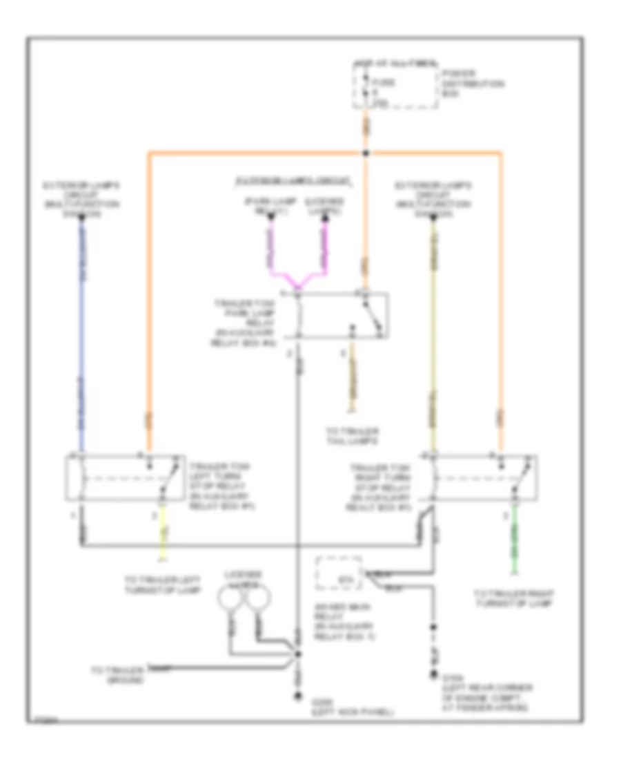
Схема Адаптера трейлера/Туриста для Ford Explorer 1996
Схема Адаптера трейлера/Туриста для Ford Explorer 1996 - Список элементов:
- (license lamps)
- (park lamp relay)
- 4wabs main relay (in auxiliary relay box 1)
- 87a
- Exterior lamps circuit
- Exterior lamps circuit (multi-function switch)
- Fuse 20a
- G104 (left rear corner of engine compt., at fender apron)
- G200 (left kick panel)
- Hot at all times
- License lamps
- Power distribution box
- To trailer left turn/stop lamp
- To trailer right turn/stop lamp
- To trailer tail lamps
- Trailer tow left turn/ stop relay (in auxiliary relay box #1)
- Trailer tow park lamp relay (in auxiliary relay box #4)
- Trailer tow right turn/ stop relay (in auxiliary realy box #1)
ВНУТРЕННЕЕ ОСВЕЩЕНИЕ
Электросхема подсветки для Ford Explorer 1996
Электросхема подсветки для Ford Explorer 1996 - Список элементов:
- Auxiliary relay box #4 (left rear of vehicle, above wheelwell)
- Bat saver rly ctrl
- Battery saver relay
- C280
- C283
- Cargo lamp
- Compass/ outside air temperature module
- Dimmer module (left side of steering column)
- Dome lamp
- Dome lamp switch
- Fuse 27 10a
- Fuse 7 30a
- G104 (left rear corner of engine compartment, at fender apron)
- G200 (left kick panel)
- G412 (rear center of vehicle, in lifgate)
- G412 (rear of vehicle)
- G500 (left front door, near master window control switch)
- G600 (right front door)
- Generic electronic module (gem) (behind center of i/p)
- Glove box lamp & switch
- Hot at all times
- Int lamp rly ctrl
- Interior fuse panel
- Interior lamp relay
- Left front door ajar switch
- Left front door courtesy lamp
- Left liftgate ajar switch
- Left rear door ajar switch
- Left vanity mirror lamp/switch
- Lf door ajar input
- Liftgate disable/ajar
- Liftgate wiper disable switch (w/ power equipment group)
- Lr door ajar input
- Map lamp
- Nca
- Pnk
- Power distribution box
- Rear dome lamp
- Rear map lamp
- Relay module (behind center of i/p)
- Rf door ajar input
- Right front door ajar switch
- Right front door courtesy lamp
- Right liftgate ajar switch
- Right rear door ajar switch
- Right vanity mirror lamp/switch
- Rr door ajar input
- Underhood lamp
- W/ overhead console only
- W/ power equipment group
- W/o overhead console only
Электросхема подсветки приборов (1 из 2) для Ford Explorer 1996
Электросхема подсветки приборов (1 из 2) для Ford Explorer 1996 - Список элементов:
- (2-door) (4-door)
- (3)
- (4-door) (2-door)
- 4x4 mode switch
- Anti-theft system
- Ashtray illum- ination
- C276
- C280
- C286
- C287
- C297
- C298
- Clock spring
- Courtesy lamps circuit
- Day/night mirror/ autolamp sensor
- Dimmer module (left side of steering column)
- Dome lamp switch
- Door lock control switch (4-door)
- Electronic automatic temperature control (eatc) module
- Exterior lights system
- Fog lamp switch
- Front panel illumination
- Fuse 3 15a
- Fuse 7 7.5a
- G100 (left front of engine compartment, near radiator)
- G104 (w/o cell. phone) (left rear corner of engine compt, at fender apron)
- G104 (w/o cellular phone) (left rear corner of engine compt, at fender apron)
- G201 (w/ cellular phone) (right side of i/p)
- G500 (left front door, near master window control switch)
- G600 (right front door)
- G700 (near left rear door lock motor)
- G800 (near right rear door lock motor)
- Generic electronic module (gem) (behind center of i/p)
- Gnd
- Head
- Headlamp switch
- Heated rear window switch
- Heater-a/c control assembly
- Hot at all times
- Ignition cylinder tamper switch
- Illumination
- Illumination (2)
- Instrument cluster
- Interior fuse panel
- Left front power door lock switch
- Left front power window switch
- Left rear power window switch
- Liftgate wiper/ washer switch
- Master window/ *
- Message center switch assembly
- Nca
- Off
- Park
- Park lamp relay
- Relay ctrl
- Relay module (behind center of i/p)
- Right front power door lock switch
- Right front power window switch
- Right rear power window switch
- Solid state
- Speed control/ horn switch assembly
- To dimmer relay (relay module)
- W/ autolamps
- W/ eatc
- W/ high series console only
- W/o eatc
- W/o high series console
Электросхема подсветки приборов (2 из 2) для Ford Explorer 1996
Электросхема подсветки приборов (2 из 2) для Ford Explorer 1996 - Список элементов:
- C2008
- C2009
- C228
- C286
- C297
- C298
- Compass/ outside air temperature module
- Dimmer relay
- Dimming indicators (power)
- Electronic automatic temperature control (eatc) module
- From dimmer module
- From park lamp relay (relay module)
- Fuse 11 7.5a
- G100 (left front of engine compt, near radiator)
- G104 (w/o cellular phone) (left rear corner of engine compt, at fender apron)
- G105 (w/o lux radio) (right rear of engine compt, on cowl panel)
- G200 (left kick panel)
- G201 (w/ cellular phone) (right side of i/p)
- G412 (rear of vehicle)
- G412 (w/ lux radio) (rear of vehicle)
- Gnd
- Head
- Headlamp relay
- Headlamp switch
- Hot in run or start
- Instrument cluster
- Instrument illumination
- Interior fuse panel
- Message center
- Off
- Park
- Radio or front control unit
- Rear integrated control panel (ricp)
- Relay module (center of i/p)
ЗАЗЕМЛЕНИЕ ПОДКЛЮЧЕНИЕ МАССЫ
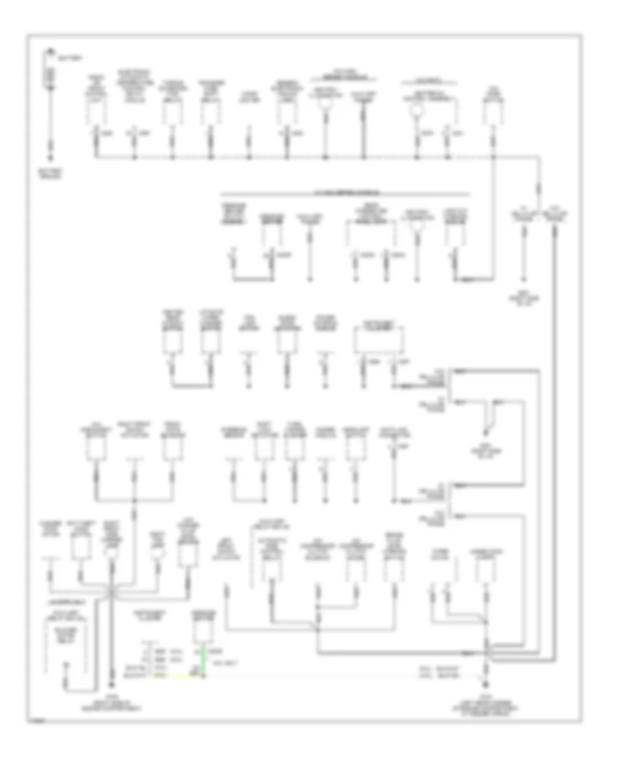
Электросхема подключение массы заземления (1 из 4) для Ford Explorer 1996
Электросхема подключение массы заземления (1 из 4) для Ford Explorer 1996 - Список элементов:
- (4.0l)
- (5.0l)
- 4x4 disconnect switch
- 4x4 mode switch
- 5.0l only
- A/c compressor clutch diode
- A/c compressor clutch solenoid
- Anti-theft hood switch
- Ashtray illumination
- Automatic ride control relay
- Auxiliary power
- Auxiliary relay box #2
- Auxiliary relay box #3
- Battery
- Battery ground
- Blend door actuator
- Blower motor relay
- Brake fluid level warning switch
- C2003
- C2004
- C2009
- C228
- C231
- C276
- C283
- C286
- C287
- C288
- C291
- C297
- Cigar lighter
- Data link connector
- Dimmer module
- Electronic automatic temperature control (eatc) module
- Fog lamp switch
- Front gate solenoid
- G104 (left rear corner of engine compartment, at fender apron)
- G105 (right side of engine compartment)
- G201 (right side of i/p)
- Generic electronic module (gem)
- Headlamp switch
- Heated rear window switch
- Heater-a/c control assembly
- Instrument cluster
- Lamp out warning module
- Left front shock actuator
- Liftgate wiper/ washer switch
- Low washer fluid level sensor
- Message center
- Message center switch assembly
- Power antenna module
- Radio or front control unit
- Rear integrated control panel (ricp)
- Right fog lamp
- Right front shock actuator
- Right front side marker lamp
- Shift lock actuator
- Steering sensor
- Torque on demand (tod) relay
- Transfer case shift relay
- Turn/ hazard flasher
- Under hood lamp
- W/ cellular phone
- W/ eatc only
- W/ high series console
- W/o cellular phone
- W/o eatc
- W/o high series console
- Washer pump motor
- Wiper motor
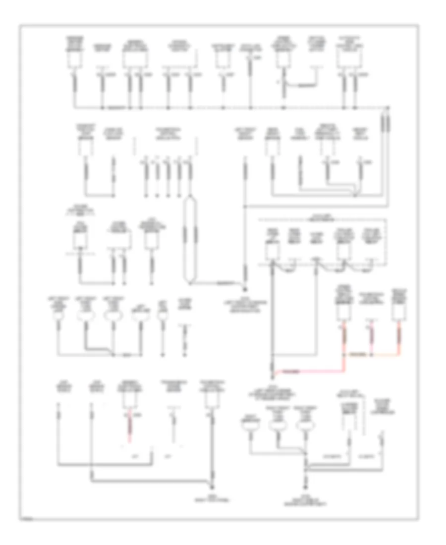
Электросхема подключение массы заземления (2 из 4) для Ford Explorer 1996
Электросхема подключение массы заземления (2 из 4) для Ford Explorer 1996 - Список элементов:
- 4wabs control module
- 4wabs main relay
- 4wabs pump motor
- 87a
- A/t
- Air bag diagnostic monitor
- Automatic ride control (arc) module
- Auxiliary relay box #1
- Auxiliary relay box #2
- Blower motor speed controller
- C2000
- C2009
- C232
- C233
- C280
- C282
- C287
- C291
- C336
- C350
- Camshaft position (cmp) sensor
- Ckp sensor shield
- Cmp sensor shield
- Data link connector
- Fuel tank assembly
- G100 (left front of engine compartment, near radiator)
- G104 (left rear corner of engine compartment, at fender apron)
- G105 (right side of engine compartment)
- G203 (right kick panel)
- Generic electronic module (gem)
- Hi-speed blower relay
- Ignition cylinder tamper switch
- Instrument cluster
- Left fog lamp
- Left front height sensor
- Left front park/ turn lamp
- Left front side marker lamp
- Left headlamp
- Low engine oil/ temperature switch
- M/t
- Mass air flow (maf) sensor
- Memory seat module
- Message center
- Message center switch assembly
- Nca
- Pcm power relay
- Power distribution box
- Powertrain control module (pcm)
- Rear height sensor
- Rear wiper down relay
- Rear wiper up relay
- Remote anti-theft personality (rap) module
- Right front park/ turn lamp
- Right headlamp
- Speed control servo/ amplifier assembly
- Speed control/ horn switch assembly
- Trailer tow left turn/stop relay
- Trailer tow right turn/stop relay
- Transmission range sensor
- Vehicle speed sensor (vss)
- W/ eatc
- W/o eatc
Электросхема подключение массы заземления (3 из 4) для Ford Explorer 1996
Электросхема подключение массы заземления (3 из 4) для Ford Explorer 1996 - Список элементов:
- 2 door
- 4 door
- 4 door only
- 4 door w/power equipment group only
- 87a
- Air ride control (arc) compressor assembly
- Auxiliary relay box #4
- Cargo lamp
- Compass/ outside air temperature module
- Day/night mirror/ autolamp sensor
- Door lock relay
- Door unlock relay
- Front fill solenoid
- Fuel tank assembly
- G200 (left kick panel)
- G500 (left front door, near master window control switch)
- G500 (near left front door speaker)
- G600 (near right front door speaker)
- G600 (right front door)
- G700 (left rear door)
- G700 (near left rear door lock motor)
- G800 (near right rear door lock motor)
- G800 (right rear door)
- Keyless entry switch assembly
- Left backup lamp
- Left front door courtesy lamp
- Left front door disarm switch
- Left front power door lock switch
- Left front power seat control switch
- Left front power window switch
- Left license lamp
- Left power bolster/ lumbar motor
- Left power/ heated mirror
- Left rear power window switch
- Left rear shock actuator
- Left stop/ park lamp
- Left turn signal lamp (rear)
- Liftgate lock switch
- Liftgate washer pump motor
- Master window/ door lock control switch
- Memory seat module
- Moonroof control switch
- Moonroof motor
- Nca
- Power mirror switch
- Rear fill solenoid
- Rear gate solenoid
- Right backup lamp
- Right front door courtesy lamp
- Right front door disarm switch
- Right front power door lock switch
- Right front power seat control switch
- Right front power window switch
- Right license lamp
- Right power lumbar motor
- Right power/ heated mirror
- Right rear power window switch
- Right rear shock actuator
- Right stop/ park lamp
- Right turn signal lamp (rear)
- Seatbelt warning switch
- Trailer tow park lamp relay
- Trailer/ camper adapter (trailer ground wire)
- W/ electronic group only
- W/ power equipment group only
- W/o power equipment group
- W/o power equipment group only
Электросхема подключение массы заземления (4 из 4) для Ford Explorer 1996
Электросхема подключение массы заземления (4 из 4) для Ford Explorer 1996 - Список элементов:
- Amplifier
- C228
- Cd changer
- Front control unit
- G105 (right rear of engine compartment, on cowl panel)
- G412 (rear center of vehicle, in liftgate)
- G412 (rear of vehicle)
- High mount stop lamp
- Left liftgate ajar switch
- Liftgate disarm switch
- Liftgate wiper disable switch
- Liftgate wiper motor
- Mobil telephone transceiver
- Nca
- Radio
- Rear integrated control panel (ricp)
- Remote chassis unit
- Right liftgate ajar switch
- Sub-woofer amplifier
- W/ am/fm/cassette
- W/ cd changer
- W/ lux radio
- W/ power equipment group
- W/ premium sound
- W/o power equipment group
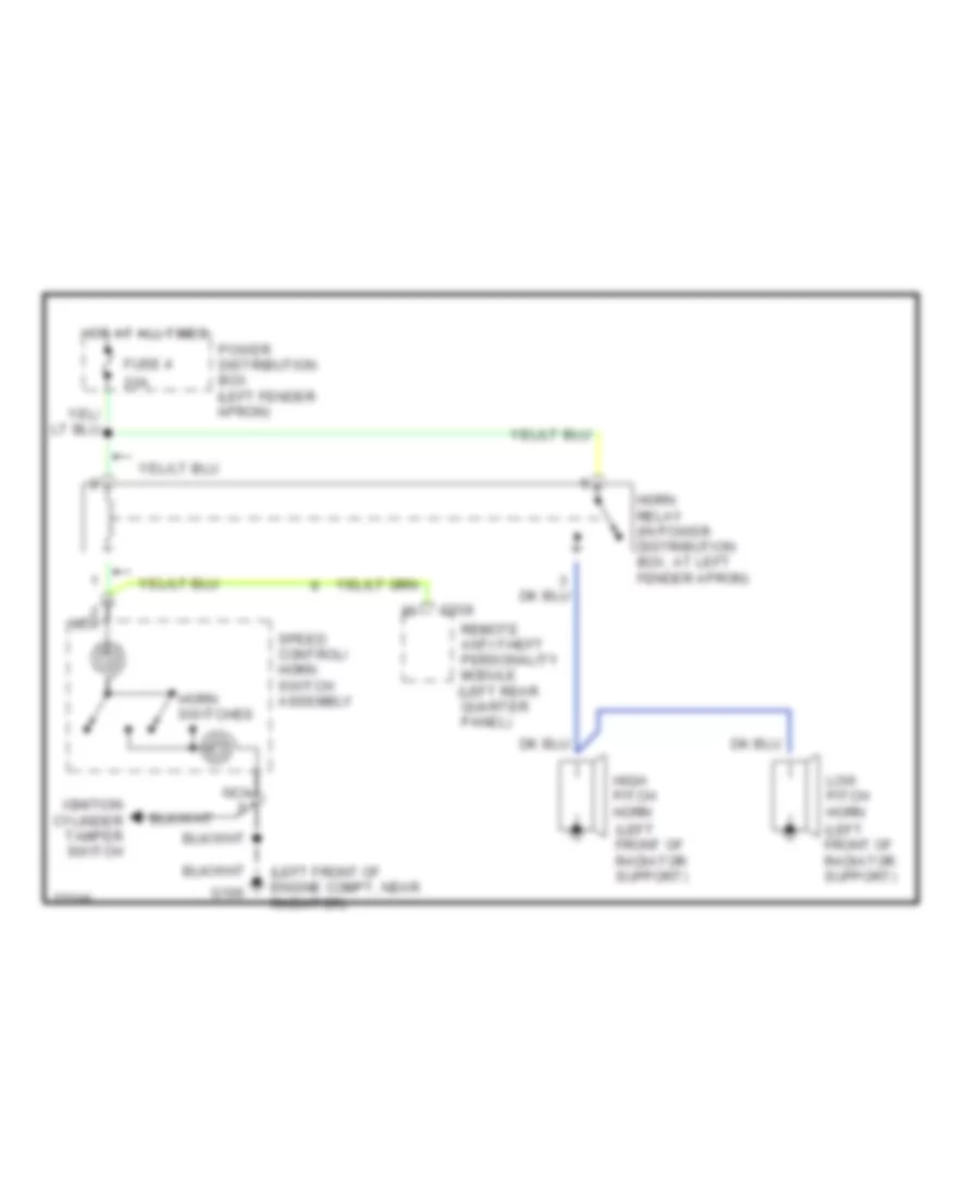
Звуковой сигнал Гудок
Электросхема звукового сигнал Гудка для Ford Explorer 1996
Электросхема звукового сигнал Гудка для Ford Explorer 1996 - Список элементов:
- (left front of engine compt, near radiator)
- (left front of radiator support)
- 20a
- C338
- Fuse 4
- G100
- High pitch horn
- Horn relay (in power distribution box, at left fender apron)
- Horn switches
- Hot at all times
- Ignition cylinder tamper switch
- Low pitch horn
- Nca
- Power distribution box (left fender apron)
- Remote anti-theft personality module (left rear quarter panel)
- Speed control/ horn switch assembly
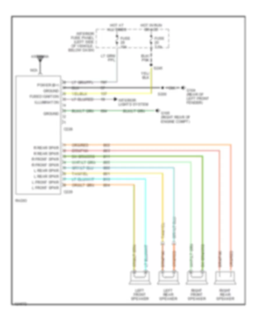
Магнитола Мультимедия
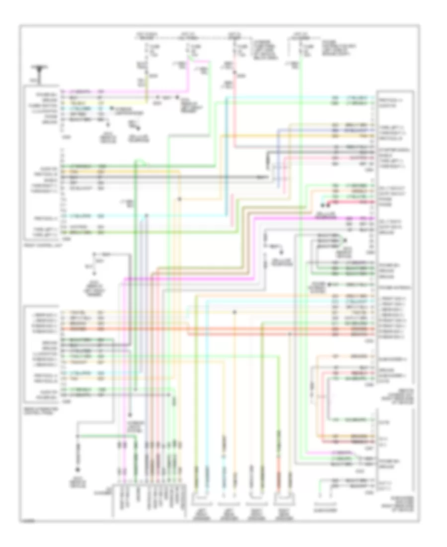
Стандартная комплектация для Ford Explorer 1996
Стандартная комплектация для Ford Explorer 1996 - Список элементов:
- Antenna
- C228
- C229
- Fuse 10a
- Fuse 7.5a
- Fused ignition
- G104 (rear of left front fender)
- G105 (right rear of engine compt)
- Ground
- Hot at all times
- Hot in run or acc
- Illuminaton
- Interior fuse panel (left side of vehicle, below dash)
- Interior lights system
- L front spkr
- L rear spkr
- Left front speaker
- Left rear speaker
- Nca
- Power (b+)
- R front spkr
- R rear spkr
- Radio
- Right front speaker
- Right rear speaker
- S200
- S245
система JBL для Ford Explorer 1996
система JBL для Ford Explorer 1996 - Список элементов:
- Antenna
- Audio on
- C228
- C256
- C264
- C265
- C332
- C333
- C386
- C387
- C388
- Cd changer
- Cd lt sig in
- Cd lt sig out
- Cd rt sig in
- Cd rt sig out
- Cellular telephone
- Front control unit
- Fuse 10a
- Fuse 30a
- Fuse 7.5a
- Fused ignition
- G104 (rear of left front fender)
- G412 (rear of vehicle)
- Ground
- Hot at all times
- Hot in run or acc
- Hot in start
- Illulminaton
- Illumination
- In (+)
- In (-)
- Interior fuse panel (left side of vehicle, below dash)
- Interior lights system
- L front sig (+)
- L front sig (-)
- L rear sig (+)
- L rear sig (-)
- Left front speaker
- Left rear speaker
- Left sig (+)
- Left sig (-)
- Mute
- Nca
- Out (+)
- Out (-)
- Phone
- Pnk
- Power (b+)
- Power antenna
- Power antenna system
- Power distribution box (left side of engine compt)
- Protocol a
- Protocol b
- R front sig (+)
- R front sig (-)
- R rear sig (+)
- R rear sig (-)
- Rear integrated control panel
- Remote chassis unit (right rear side of vehicle)
- Right front speaker
- Right rear speaker
- Right sig (+)
- Right sig (-)
- S200
- S231
- S243
- S245
- S355
- Shield
- Starter signal
- Subwoofer
- Subwoofer (+)
- Subwoofer (-)
- Subwoofer amplifier (right rear side of vehicle)
- Tan
- Tape left (+)
- Tape left (-)
- Tape right (+)
- Tape right (-)
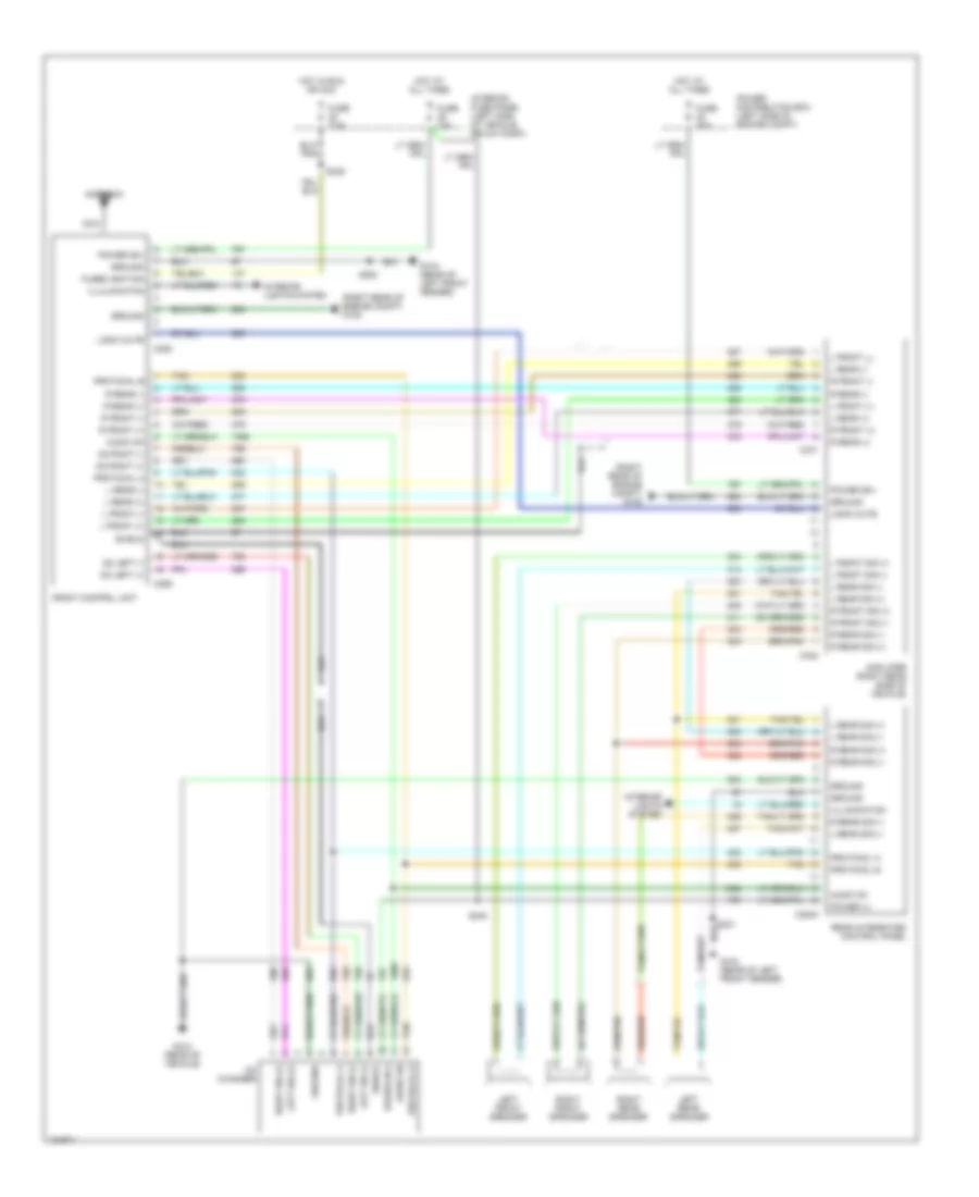
Электросхема премиум магнитолы, С CD-плеер для Ford Explorer 1996
Электросхема премиум магнитолы, С CD-плеер для Ford Explorer 1996 - Список элементов:
- (right rear of engine compt) g105
- Amplifier (right rear side of vehicle)
- Antenna
- Audio on
- C2003
- C228
- C256
- C331
- C332
- Cd changer
- Cd left (+)
- Cd left (-)
- Cd right (+)
- Cd right (-)
- Front control unit
- Fuse 10a
- Fuse 30a
- Fuse 7.5a
- Fused ignition
- G104 (rear of left front fender)
- G412 (rear of vehicle)
- Ground
- Hot at all times
- Hot in run or acc
- Iillumination
- Illulminaton
- Interior fuse panel (left side of vehicle, below dash)
- Interior lights system
- L front (+)
- L front (-)
- L front (_)
- L front sig (+)
- L front sig (-)
- L rear (+)
- L rear (-)
- L rear sig (+)
- L rear sig (-)
- Left front speaker
- Left rear speaker
- Left sig (+)
- Left sig (-)
- Logic mute
- Nca
- Power (+)
- Power (b+)
- Power distribution box (left side of engine compt)
- Protocal a
- Protocal b
- Protocol a
- Protocol b
- R front (+)
- R front (-)
- R front sig (+)
- R front sig (-)
- R rear (+)
- R rear (-)
- R rear sig (+)
- R rear sig (-)
- Rear integrated control panel
- Right front speaker
- Right rear speaker
- Right sig (+)
- Right sig (-)
- S200
- S231
- S243
- S245
- Shield
- Tan
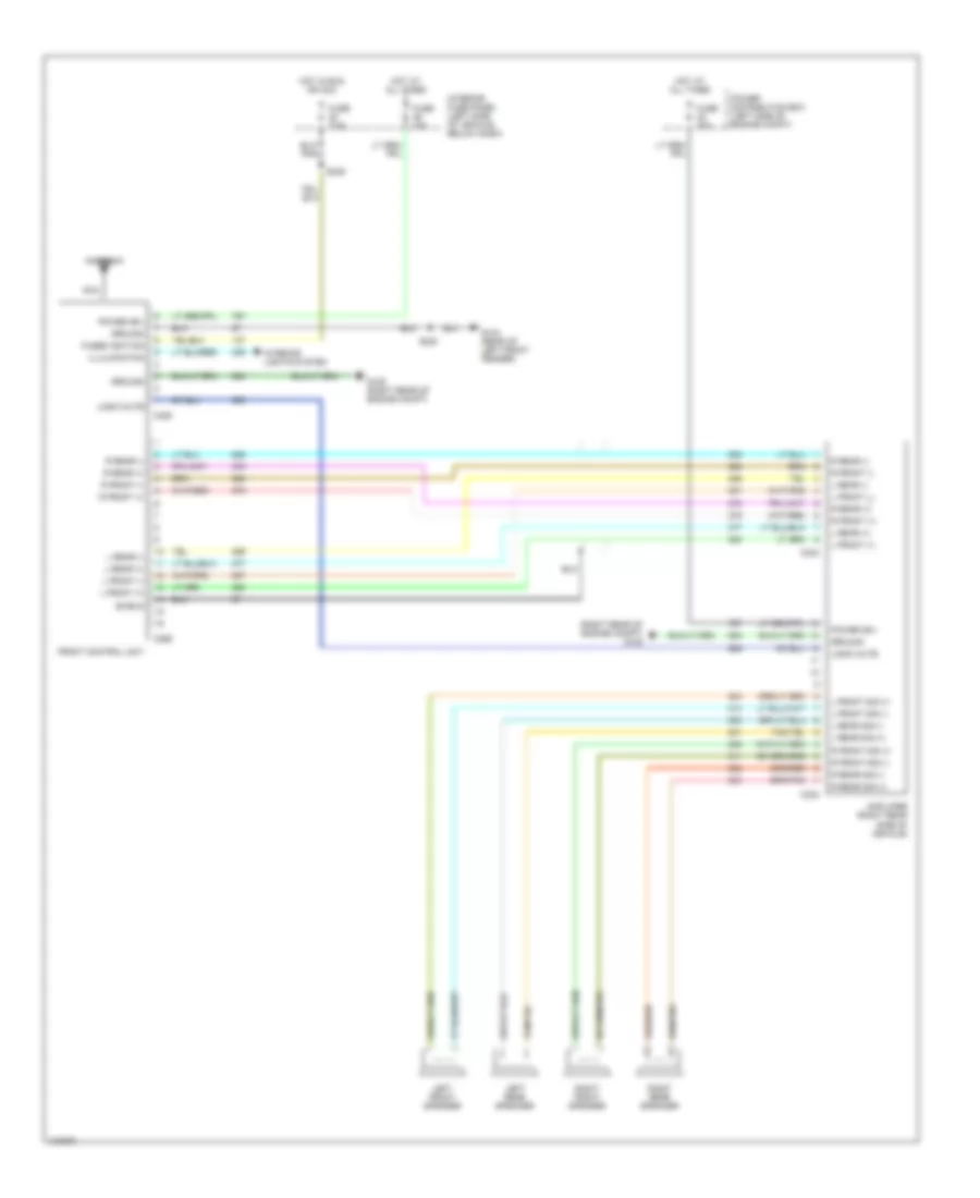
Электросхема премиум магнитолы, без CD-плеер для Ford Explorer 1996
Электросхема премиум магнитолы, без CD-плеер для Ford Explorer 1996 - Список элементов:
- (right rear of engine compt) g105
- Amplifier (right rear side of vehicle)
- Antenna
- C228
- C256
- C332
- Front control unit
- Fuse 10a
- Fuse 30a
- Fuse 7.5a
- Fused ignition
- G104 (rear of left front fender)
- G105 (right rear of engine compt)
- Ground
- Hot at all times
- Hot in run or acc
- Illulminaton
- Interior fuse panel (left side of vehicle, below dash)
- Interior lights system
- L front (+)
- L front (-)
- L front (_)
- L front sig (+)
- L front sig (-)
- L rear (+)
- L rear (-)
- L rear sig (+)
- L rear sig (-)
- Left front speaker
- Left rear speaker
- Logic mute
- Nca
- Power (b+)
- Power distribution box (left side of engine compt)
- R front (+)
- R front (-)
- R front sig (+)
- R front sig (-)
- R rear (+)
- R rear (-)
- R rear sig (+)
- R rear sig (-)
- Right front speaker
- Right rear speaker
- S200
- S245
- Shield
Подогрев стекол и зеркал
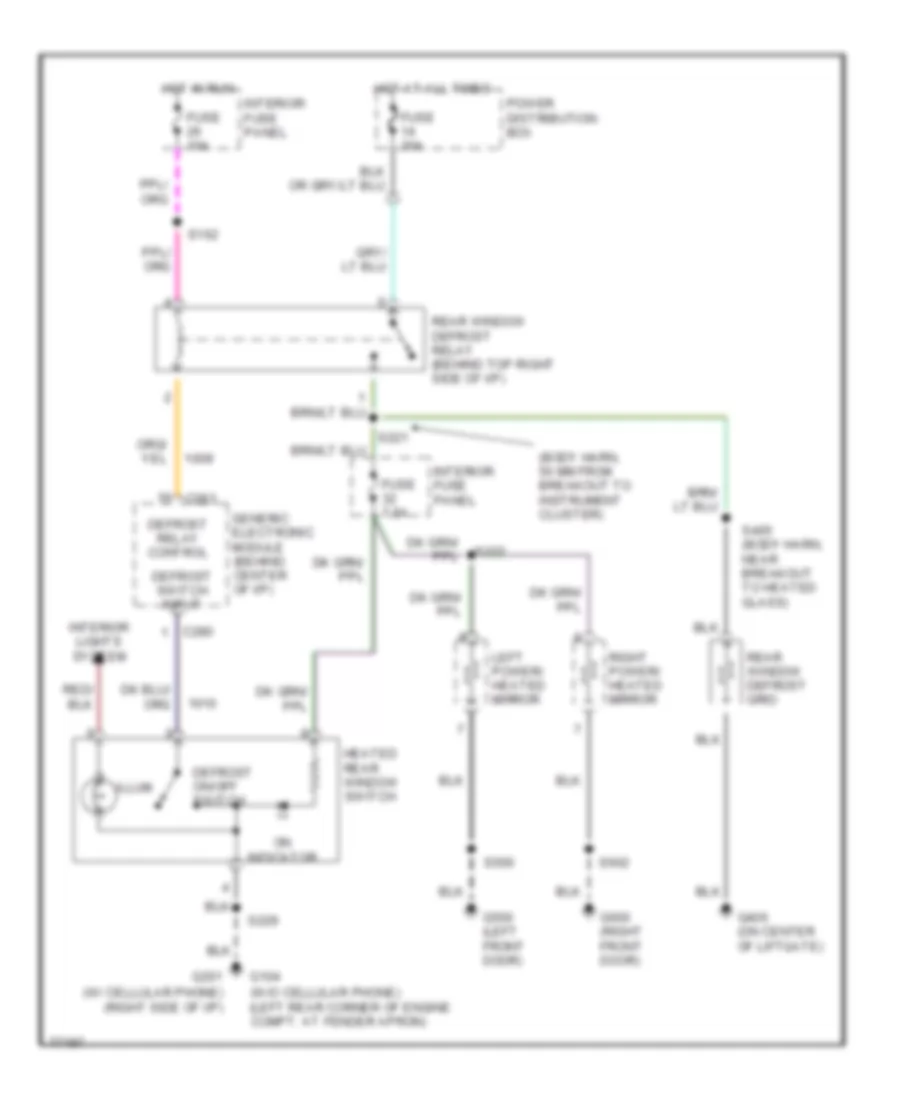
Электросхема подогрева стекол и зеркал для Ford Explorer 1996
Электросхема подогрева стекол и зеркал для Ford Explorer 1996 - Список элементов:
- (body harn, 50 mm from breakout to instrument cluster)
- (w/ cellular phone) (right side of i/p)
- (w/o cellular phone) (left rear corner of engine compt. at fender apron)
- C280
- C283
- Defrost on/off switch
- Defrost relay control
- Defrost switch input
- Fuse 10a
- Fuse 30a
- Fuse 7.5a
- G104
- G201
- G406 (on center of liftgate)
- G500 (left front door)
- G600 (right front door)
- Generic electronic module (behind center of i/p)
- Heated rear window switch
- Hot at all times
- Hot in run
- Illum
- Interior fuse panel
- Interior lights system
- Left power/ heated mirror
- On indicator
- Power distribution box
- Rear window defrost grid
- Rear window defrost relay (behind top right side of i/p)
- Right power/ heated mirror
- S162
- S221
- S222
- S229
- S405 (body harn, near breakout to heated glass)
- S500
- S602
ПОДУШКИ БЕЗОПАСНОСТИ AIR BAG
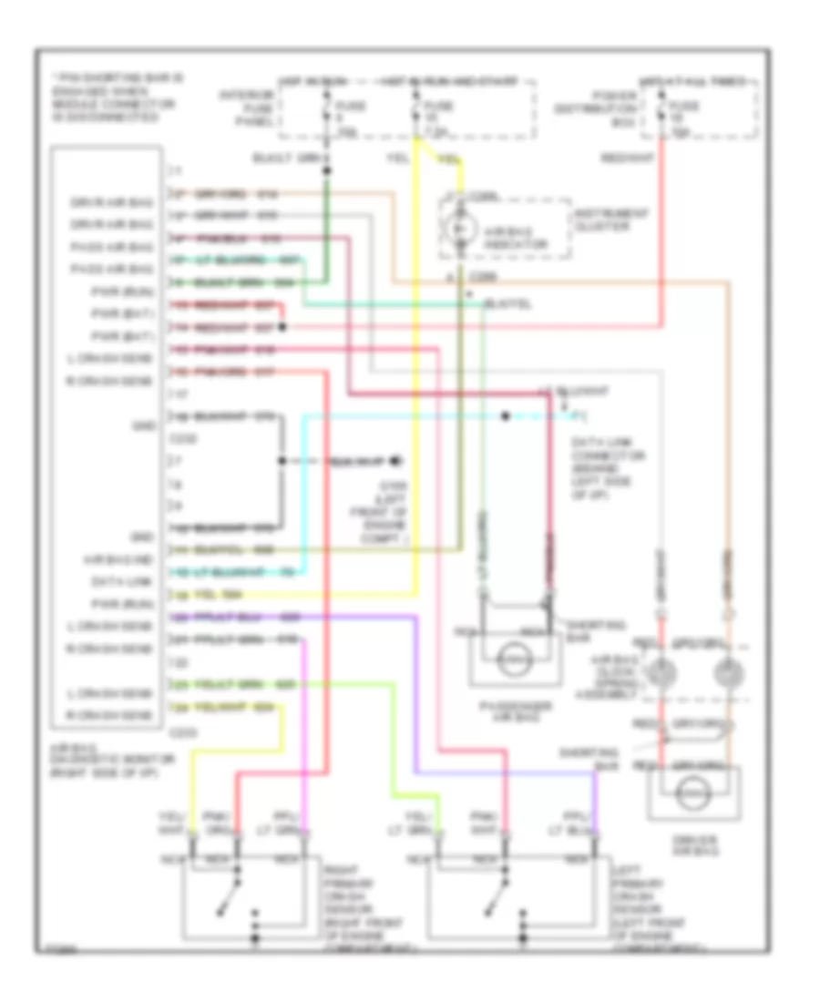
Электросхема подушек безопасности SRS AirBag для Ford Explorer 1996
Электросхема подушек безопасности SRS AirBag для Ford Explorer 1996 - Список элементов:
- * pin shorting bar is engaged when module connector is disconnected
- Air bag clock- spring assembly
- Air bag diagnostic monitor (right side of i/p)
- Air bag ind
- Air bag indicator
- C232
- C233
- C288
- Data link
- Data link connector (behind left side of i/p)
- Driver air bag
- Drvr air bag
- Fuse 10a
- Fuse 7.5a
- G100 (left front of engine compt.)
- Gnd
- Hot at all times
- Hot in run
- Hot in run and start
- Instrument cluster
- Interior fuse panel
- L crash sens
- Left primary crash sensor (left front of engine compartment)
- Nca
- Pass air bag
- Passenger air bag
- Power distribution box
- Pwr (bat)
- Pwr (run)
- R crash sens
- Red
- Right primary crash sensor (right front of engine compartment)
- Shorting bar
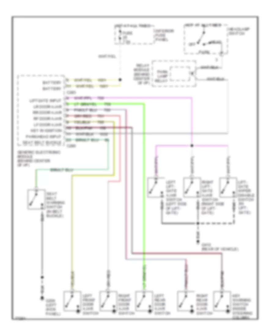
ПРЕДУПРЕЖДАЮЩИЕ СИСТЕМЫ
Электросхема предупреждающей системы для Ford Explorer 1996
Электросхема предупреждающей системы для Ford Explorer 1996 - Список элементов:
- Battery
- C280
- C283
- Fuse 7.5a
- G200 (left (kick panel)
- G412 (rear of vehicle)
- Generic electronic module (behind center of i/p)
- Head
- Headlamp switch
- Hot at all times
- Interior fuse panel
- Key in ignition
- Key warning switch (inside steering column)
- Left front door ajar switch
- Left lift- gate ajar switch (left side of lift- gate)
- Left rear door ajar switch
- Lf door ajar
- Lift- gate wiper disable switch (in lift- gate)
- Liftgate input
- Lr door ajar
- Off
- Park
- Park lamp relay
- Park/head input
- Relay module (behind center of i/p)
- Rf door ajar
- Right front door ajar switch
- Right lift- gate ajar switch (right side of lift- gate)
- Right rear door ajar switch
- Rr door ajar
- Seat belt buckle
- Seat belt warning switch (in belt buckle)
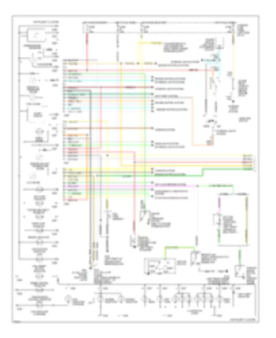
ПРИБОРНАЯ ПАНЕЛЬ
комплект приборов и схема центра сообщений (1 из 2) для Ford Explorer 1996
комплект приборов и схема центра сообщений (1 из 2) для Ford Explorer 1996 - Список элементов:
- "anti-theft" indicator
- "brake" indicator
- "door ajar" indicator
- "fasten seatbelt" indicator
- (4.ol)
- (5.0l)
- 4.0l
- 4.32k
- 4wd indicator (hi-range)
- 4wd indicator (lo-range)
- 5.0l
- Acc
- Air bag indicator
- Anti-lock brakes system
- Anti-lock indicator
- Anti-theft system
- Brake fluid level warning switch (brake fluid reservoir) low
- C286
- C287
- C288
- Charge indicator
- Check gauge
- Cruise control system
- Daytime running lamps (drl) module (left front corner of eng. compt.)
- Dc out
- Dimmer module (left side of steering column)
- Dimmer relay (in relay module, behind center of i/p)
- Engine controls system
- Engine coolant temperature gauge
- Engine coolant temperature sender (left front of engine)
- Engine oil pressure gauge
- Engine oil pressure switch (next to power steering pump)
- Exterior lights system
- Fuel guage
- Fuel reset switch indicator
- Fuel tank assembly
- Fuse 15a
- Fuse 7.5a
- G100 (left front of engine compt., near radiator)
- G104 (left rear corner of engine compt., at fender apron)
- G104 (w/o cellular phone) (left rear corner of engine compt., at fender apron)
- G201 (w/ cellular phone) (right side of i/p)
- Head
- Headlamp switch
- Headlights system
- Hi beam
- Hot at all times
- Hot in run or start
- Ignition switch
- Illumination lamps
- Instrument cluster
- Interior fuse panel (left side of i/p)
- Interior lights system
- Left turn
- Lock
- Malfunction indicator lamp
- Off
- Park
- Parking brake switch (on parking brake lever)
- Right turn
- Run
- Slosh module
- Speed control indicator
- Speedometer/ odometer
- Start
- Starting/charging system
- Tachometer
- Tachometer data link connector (right rear corner of engine compt)
- Transmission control indicator (tcil)
- Voltmeter
- W/ drl
- W/o drl
- Warning system
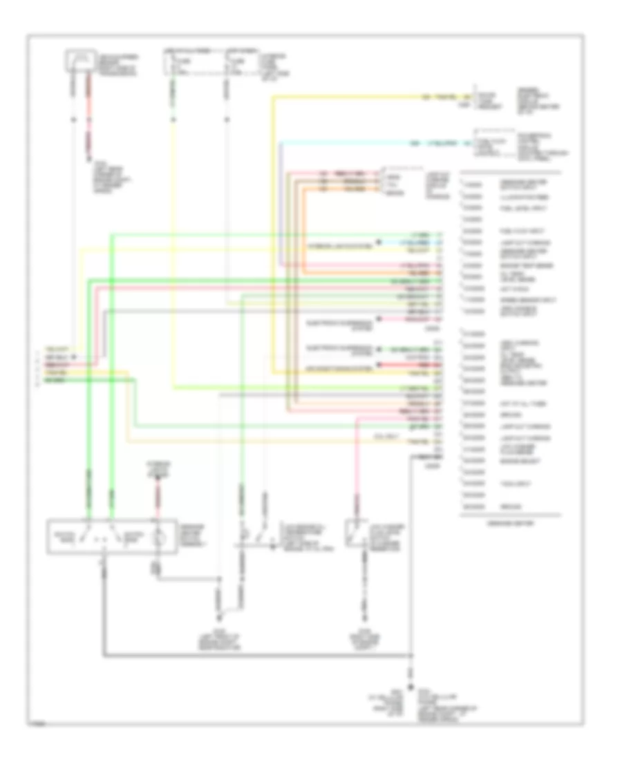
комплект приборов и схема центра сообщений (2 из 2) для Ford Explorer 1996
комплект приборов и схема центра сообщений (2 из 2) для Ford Explorer 1996 - Список элементов:
-
- (arc) disable switch input
- (arc) warning input oil temp/ level sense english/metric output (gem) to message center
- 1/c2008
- 10/c2008
- 11/c2008
- 12/c2008
- 2/c2008
- 21/c2009
- 22/c2009
- 23/c2009
- 24/c2009
- 25/c2009
- 26/c2009
- 27/c2009
- 28/c2009
- 29/c2009
- 3/c2008
- 30/c2009
- 31/c2009
- 32/c2009
- 33/c2009
- 34/c2009
- 35/c2009
- 36/c2009
- 4/c2008
- 5.0l only
- 5/c2008
- 6/c2008
- 7/c2008
- 8/c2008
- 9/c2008
- Air conditioning system
- Brake
- C2008
- C2009
- C280
- Electronic suspension system
- Engine select
- Engine temp sense
- Fuel flow input
- Fuel flow rate output
- Fuel level input
- Fuse 10a
- Fuse 7.5a
- G100 (left front of engine compt., near radiator)
- G104 (left rear corner of engine compt., at fender apron)
- G104 (w/o cellular phone) (left rear corner of engine compt., at fender apron)
- G105 (right side of engine compt.)
- G201 (w/ cellular phone) (right side of i/p)
- Generic electronic module (behind center of i/p)
- Ground
- Head
- Hot at all times
- Hot in run
- Illumination feed
- Interior fuse panel (left side of i/p)
- Interior lights system
- Lamp out warning
- Lamp out warning module (in console)
- Low engine oil/ temperature switch (left side of engine, at oil pan)
- Low washer fluid level switch (in washer reservoir)
- Low washer fluid sense
- Message center
- Message center switch assembly
- Message center switch input
- Oil temp/ level sense
- Powertrain control module (mounted through cowl panel)
- Red
- Sound tone request
- Speed sensor input
- Switch bank
- Tach input
- Tail
- Vehicle speed sensor (right side of transmission)
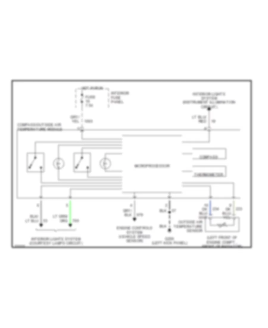
Электросхема верхней консоли управления для Ford Explorer 1996
Электросхема верхней консоли управления для Ford Explorer 1996 - Список элементов:
- (left front of engine compt., front of radiator)
- Compass
- Compass/outside air temperature module
- Engine controls system (vehicle speed sensor)
- Fuse 7.5a
- G200 (left kick panel)
- Hot in run
- Interior fuse panel
- Interior lights system (courtesy lamps circuit)
- Interior lights system (instrument illumination circuit)
- Microprocessor
- Outside air temperature sensor
- Thermometer
ПРИВОД ЗЕРКАЛ
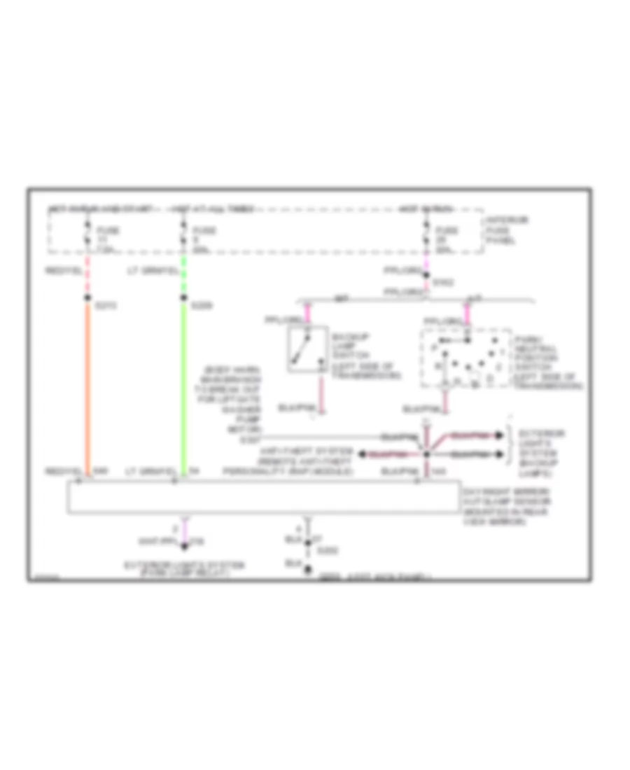
фотохромовая схема зеркала для Ford Explorer 1996
фотохромовая схема зеркала для Ford Explorer 1996 - Список элементов:
- (body harn, main branch to break out for liftgate washer pump motor) s307
- (left kick panel)
- A/t
- Anti-theft system (remote anti-theft personality (rap) module)
- Backup lamp switch (left side of transmission)
- Day/night mirror/ autolamp sensor (mounted in rear view mirror)
- Exterior lights
- Exterior lights system (park lamp relay)
- Fuse 10a
- Fuse 7.5a
- G200
- Hot at all times
- Hot in run
- Hot in run and start
- Interior fuse panel
- M/t
- Park/ neutral position switch (left side of transmission)
- S162
- S202
- S209
- S213
- System (backup lamps)
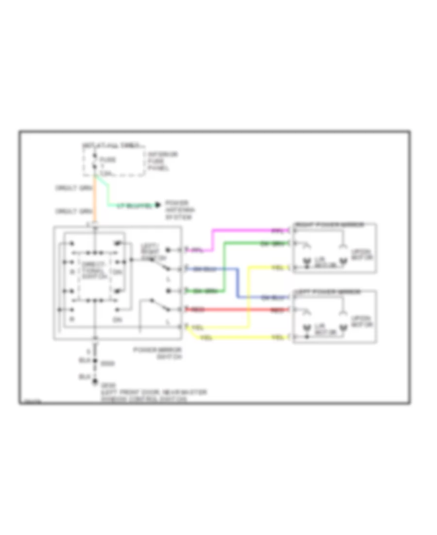
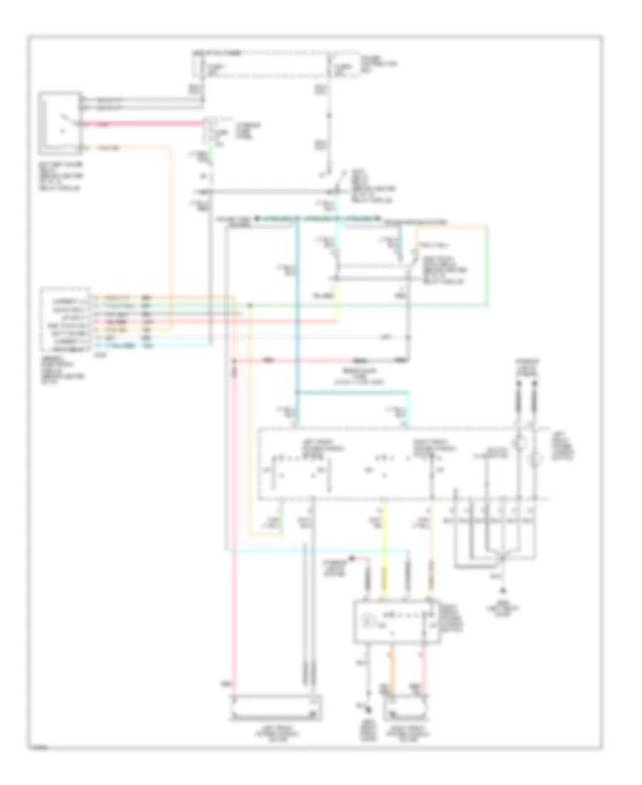
Электросхема привода зеркал для Ford Explorer 1996
Электросхема привода зеркал для Ford Explorer 1996 - Список элементов:
- Direct- tional switch
- Fuse 7.5a
- G500 (left front door, near master window control switch)
- Hot at all times
- Interior fuse panel
- L/r motor
- Left power mirror
- Left/ right switch
- Power antenna system
- Power mirror switch
- Red
- Right power mirror
- S500
- Up/dn motor
ПРИВОД ЛЮКА И КРЫШИ
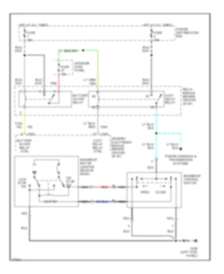
Электросхемы привода люка или крыши для Ford Explorer 1996
Электросхемы привода люка или крыши для Ford Explorer 1996 - Список элементов:
- Accy delay relay
- Accy delay relay ctrl
- Battery saver relay
- Battery saver relay ctrl
- C283
- Ccw stop sw
- Close
- Clutch
- Cw stop sw
- Fuse 10a
- Fuse 30a
- G200 (left kick panel)
- Generic electronic module (behind center of i/p)
- Hot at all times
- Interior fuse panel
- Moonroof control switch
- Moonroof motor (center rear of roof)
- Nca
- Open
- Pnk
- Power distribution box
- Power windows & transmission systems
- Red
- Relay module (behind center of i/p)
ПРИВОД СТЕКЛОПОДЪЕМНИКОВ
Электросхема стеклоподъемников, 2 двери для Ford Explorer 1996
Электросхема стеклоподъемников, 2 двери для Ford Explorer 1996 - Список элементов:
- Accy delay
- Accy delay relay (behind center of i/p, in relay module)
- Batt saver
- Battery saver relay (behind center of i/p, in relay module)
- C238
- Current hi
- Current lo
- Down input
- Fuse 10a
- Fuse 5 30a
- Fuse 7 30a
- G500 (left front door)
- G600 (right front door)
- Generic electronic module (behind center of i/p)
- Hot at all times
- Interior fuse panel
- Interior lights system
- Left front power window motor
- Left front power window switch
- One touch dn
- One touch down relay (behind center of i/p, in relay module)
- Pnk
- Power distribution box
- Power tops system
- Red
- Resistance wire (0.015 +/- 0.001 ohm)
- Right front power window motor
- Right front power window switch
- Switch illumination
- Transmissions system
- Up input
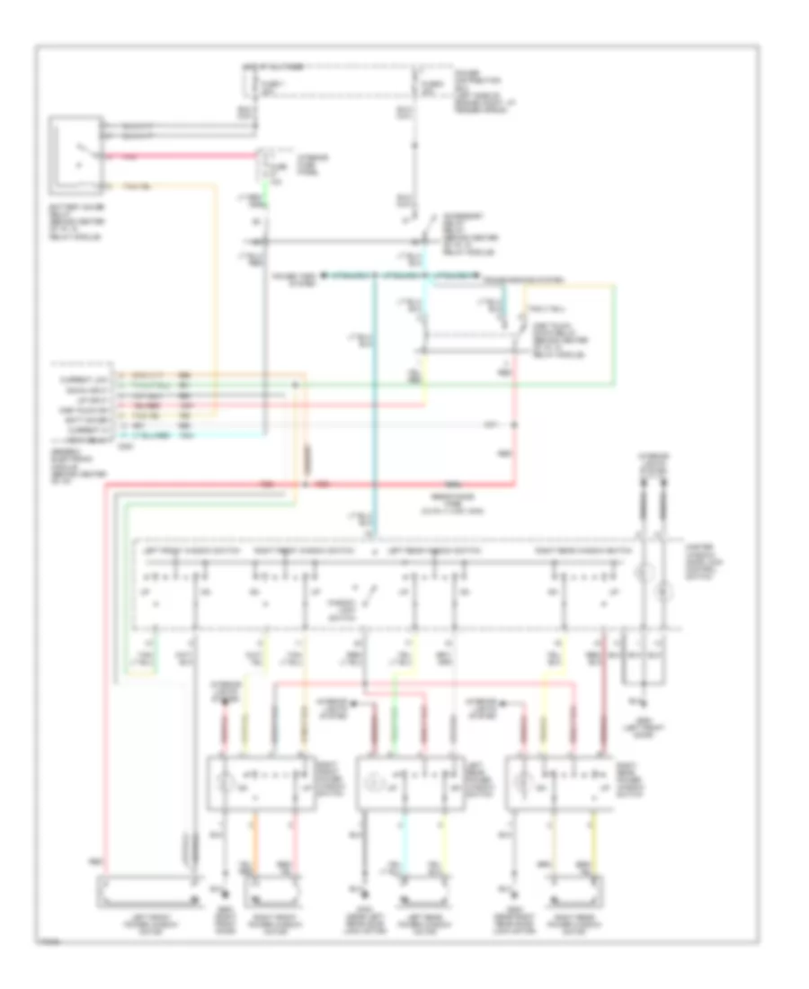
Электросхема стеклоподъемников, 4 двери для Ford Explorer 1996
Электросхема стеклоподъемников, 4 двери для Ford Explorer 1996 - Список элементов:
- Accessory delay relay (behind center of i/p, in relay module)
- Accy delay
- Batt saver
- Battery saver relay (behind center of i/p, in relay module)
- C283
- Current hi
- Current low
- Down input
- Fuse 10a
- Fuse 5 30a
- Fuse 7 30a
- G500 (left front door)
- G600 (right front door)
- G700 (near left rear door lock motor)
- G800 (near right rear door lock motor)
- Generic electronic module (behind center of i/p)
- Hot at all times
- Interior fuse panel
- Interior lights system
- Left front power window motor
- Left front window switch
- Left rear power window motor
- Left rear power window switch
- Left rear window switch
- Master window/ door lock control switch
- One touch dn
- One touch down relay (behind center of i/p, in relay module)
- Pnk
- Power distribution box (left side of engine compt, at fender apron)
- Power tops system
- Red
- Resistance wire (0.015 +/- 0.001 ohm)
- Right front power window motor
- Right front power window switch
- Right front window switch
- Right rear power window motor
- Right rear power window switch
- Right rear window switch
- Transmissions system
- Up input
- Window lock switch
Противоугонная система Сигнализация
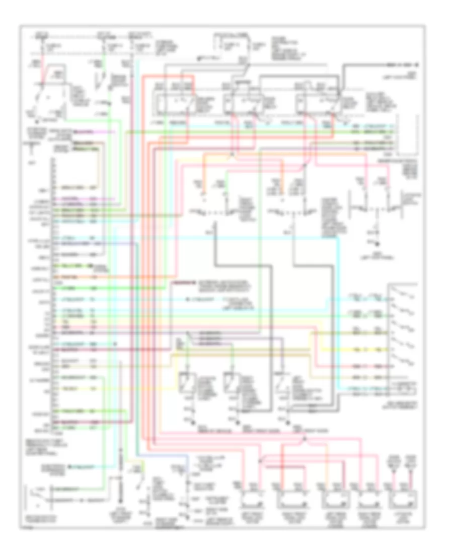
Электросхема противоугонной сигнализации для Ford Explorer 1996
Электросхема противоугонной сигнализации для Ford Explorer 1996 - Список элементов:
- "r" input
- (4 dr) (2 dr)
- (left rear of engine compt)
- (left side of i/p)
- (or pnk)
- (right side of engine compartment)
- (right side of i/p)
- * w/o cellular
- ** w/ cellular
- 1/2
- 3/4
- 5/6
- 7/8
- 87a
- 9/0
- Ant
- Antenna
- Anti- theft hood switch (closed w/ hood open)
- Anti- theft relay (in relay module)
- Anti-theft indicator
- Auxiliary relay box 4 (left rear of vehicle, above wheel well)
- Bat
- Boo sw
- Brake on/off switch
- C280
- C281
- C286
- C287
- C336
- C338
- Com
- Data
- Data link connector
- Disarm
- Door ajar
- Door lock relay
- Door unlock relay
- Driver's door unlock relay
- Electronic suspension system
- Exterior lights system (trans. range sensor-a/t) (backup lamp switch-m/t)
- Fuse 12 20a
- Fuse 13 15a
- Fuse 20 7.5a
- Fuse 24 10a
- Fuse 5 30a
- G104 *
- G105
- G1o0 (left front of engine compt.)
- G200 (left kick panel)
- G201 **
- G412 (rear of vehicle)
- G500 (left front door)
- G600 (right front door)
- Generic electronic module (behind center of i/p)
- Ground
- Headlights system (autolamps)
- Hood sw
- Horn rly
- Horns system
- Hot at all times
- Hot in accy or run
- Hot in start
- Ig tamper
- Ign
- Ignition switch tamper switch
- Illumination
- Ind led
- Instrument cluster
- Int lights
- Interior fuse panel (left side of i/p)
- Keyless entry switch assembly
- Kypd illum
- Left front door disarm switch (closed if opened w/ key)
- Left front door lock motor
- Left rear door lock motor (4 door)
- Liftgate disarm switch (closed if opened w/key)
- Liftgate lock motor
- Liftgate lock switch
- Lo beam
- Lock
- Lock all
- Master window/ door lock control switch (4 door) left front power door lock switch (2 door)
- Mem 1
- Mem 2
- Memory system
- Nca
- Phone
- Power distribution box (left side of engine compt, at fender apron)
- Red
- Remote anti-theft personality module (left rear quarter panel)
- Right front door disarm switch (closed if opened w/key)
- Right front door lock motor
- Right front power door lock switch
- Right rear door lock motor (4 door)
- Starting/ charging system
- Strtr int
- Unlck
- Unlck all
- Unlck lf
СИСТЕМА АНТИБЛОКИРОВОЧНОЙ ТОРМОЗНОЙ СИСТЕМЫ ABS
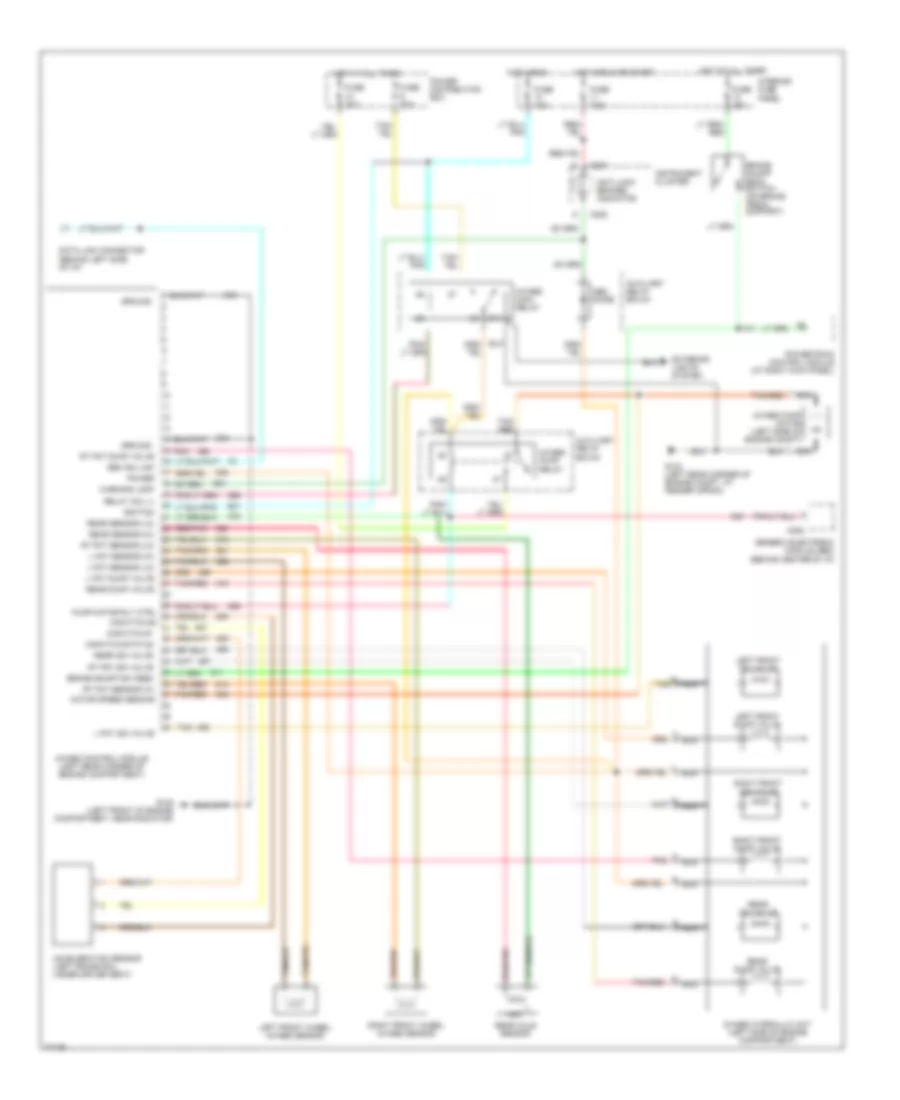
Электросхема антиблокировочной тормозной системы АБС (ABS) для Ford Explorer 1996
Электросхема антиблокировочной тормозной системы АБС (ABS) для Ford Explorer 1996 - Список элементов:
- 4wabs control module (left rear corner of engine compartment)
- 4wabs hydraulic unit (left side of engine compartment)
- 4wabs main relay
- 4wabs pump motor (left side of engine compt)
- 4wabs pump relay
- 87a
- Abs diode
- Acceleration sensor (left frame rail, under driver seat)
- Anti-lock brakes indicator
- Auxiliary relay box #1
- Brake on/off (boo) switch (on brake pedal support)
- Brake on/off sw feed
- C282
- C287
- C288
- Data link connector (behind left side of i/p)
- Exterior lights system
- Fuse 10a
- Fuse 15a
- Fuse 30a
- Fuse 7.5a
- G-switch #1
- G-switch status
- G104 (left rear corner of engine compt, at fender apron)
- G108 (left front of engine compartment, near radiator)
- Gem iso link
- Generic electronic module (gem) (behind center of i/p)
- Ground
- Hot at all times
- Hot in run
- Hot in run or start
- Ignition
- Instrument cluster
- Interior fuse panel
- L fnt dump valve
- L fnt iso valve
- L fnt sensor (hi)
- L fnt sensor (lo)
- Left front dump valve
- Left front iso valve
- Left front wheel 4wabs sensor
- Motor speed sens #2
- Nca
- Pnk
- Power
- Power distribution box
- Powertrain control module (at right kick panel)
- Pump motor rly ctrl g-switch #2
- Rear axle sensor
- Rear dump valve
- Rear iso valve
- Rear sensor (hi)
- Rear sensor (lo)
- Red/pnk
- Relay coil (-)
- Right front dump valve
- Right front iso valve
- Right front wheel 4wabs sensor
- Rt fnt dump valve
- Rt fnt iso valve
- Rt fnt sensor (hi)
- Rt fnt sensor (lo)
- Tan
- Tan/ red
- Tan/red
- Warning lamp
СИСТЕМА КОНДИЦИОНЕРА
Электросхема кондиционера A/C, Авто A/C для Ford Explorer 1996
Электросхема кондиционера A/C, Авто A/C для Ford Explorer 1996 - Список элементов:
- (right side of engine compt)
- A/c compressor clutch
- A/c clutch cycling pressure switch (right side of engine compartment)
- A/c clutch diode
- A/c clutch out
- A/c plenum)
- Ambient temp input
- Ambient temperature sensor (left front of engine compartment)
- Battery
- Blend door act
- Blend door actuator (behind right side of i/p, top of
- Blend door pot
- Blend door ref
- Blower motor
- Blower motor relay (in auxiliary relay box 2)
- Blower motor speed
- Blower motor speed controller (near blower motor)
- Blower spped fback
- Data line
- Data link connector (behind left side of i/p)
- Electronic automatic temperature control module (center of i/p)
- Eng/met conv
- Fuse 10a
- Fuse 15a
- Fuse 50a
- Fuse 7.5a
- G103
- G103 (right side of engine compartment)
- G104 (left rear corner of engine compartment)
- G202 (under right side of i/p)
- Ground
- Hot at all times
- Hot in run
- I/p fuse panel
- Ignition
- Illumination
- In car temp sens
- In-car temperature sensor
- Instrument cluster (digital)
- Interior lights system
- Med
- Off
- Pcm power relay
- Power distribution box
- Powertrain control module (behind left side of i/p on left side of safety wall)
- Rear blower motor
- Rear blend door actuator (in i/p console)
- Rear blower motor relay (behind right side of i/p)
- Rear blower motor resistor (in i/p console)
- Rear integrated control panel
- Red
- Relay signal
- Sensor ground
- Sun load sensor (top right side of i/p, above glove box)
- Sunload sens input
- Wac switch (left side of engine compartment)
- Wot a/c relay (in power distribution box)
Электросхема кондиционера A/C, Ручное управление A/C для Ford Explorer 1996
Электросхема кондиционера A/C, Ручное управление A/C для Ford Explorer 1996 - Список элементов:
- (in auxiliary relay box 2)
- (left rear corner of engine compartment)
- A/c clutch cycling pressure switch (right side of engine compartment at accumulator)
- A/c clutch diode
- A/c compres- sor clutch solenoid
- Blend door actuator (behind right side of i/p on a/c plenum)
- Blower motor
- Blower motor relay (in auxiliary relay box 2)
- Blower motor resistor (near blower motor)
- Blower motor switch
- C231
- C276
- Cold
- Def
- Def/flr
- Flr
- Fuse 10a
- Fuse 15a
- Fuse 50a
- Fuse 7.5a
- G103 (right side of engine compartment)
- G104
- G201 (right side of i/p)
- Heater-a/c control assembly
- High speed blower relay
- Hot at all times
- Hot in run
- Illumi- nation
- Interior fuse panel
- Interior lights system
- Low
- Max
- Med
- Norm
- Off
- Pan/flr
- Panel
- Pcm power relay
- Power distribution box
- Powertrain control module (center of safety wall)
- Rear air door actuator
- Rear blower motor
- Rear blower motor relay (behind right side of i/p)
- Rear blower motor resistor (in i/p console)
- Rear inte- grated control panel
- Red
- Solid state
- Temperature control potentiometer
- Wac switch (left side of engine compartment, at a/c discharge hose)
- Warm
- Wot a/c relay (in power distribution box)
СИСТЕМА КРУИЗКОНТРОЛЯ
Электросхема системы круизконтроля для Ford Explorer 1996
Электросхема системы круизконтроля для Ford Explorer 1996 - Список элементов:
- A/t w/ console
- A/t w/o console
- Accel
- Brake on/off (boo) switch (on brake pedal support)
- Brake on/off sw in
- Brake press input
- Brake pressure switch (left rear corner of engine compartment)
- C286
- Clock spring
- Clutch pedal position (cpp) switch (on clutch pedal arm)
- Clutch pedal position (cpp) switch jumper (left side of i/p, taped to main harness)
- Coast
- Fuse 15a
- Fuse 7.5a
- G100 (left front of engine compt. near radiator)
- G104 (left rear corner of engine compartment, at fender apron)
- Ground
- Horn switches
- Horn system
- Hot at all times
- Hot in run
- Ignition
- Ignition cylinder tamper switch
- Illumination
- Instrument cluster
- Instrument cluster system (headlamp switch, pin 8)
- Instrument cluster, body computer & electronic suspension systems
- Interior fuse panel
- Interior lights system
- M/t
- Nca
- Off
- Ohms
- Powertrain control module (pcm) (right rear of engine compartment)
- Resume
- Set/
- Speed cont lp out
- Speed cont sw gnd
- Speed cont sw in
- Speed control indicator
- Speed control servo/ amplifier assembly (right rear of engine compartment)
- Speed control/ horn switch assembly (in steering column assembly)
- Vehicle speed input
- Vehicle speed sensor (vss) (on transmission)
- Vss input
СИСТЕМА ПЕРЕДАЧИ ДАННЫХ
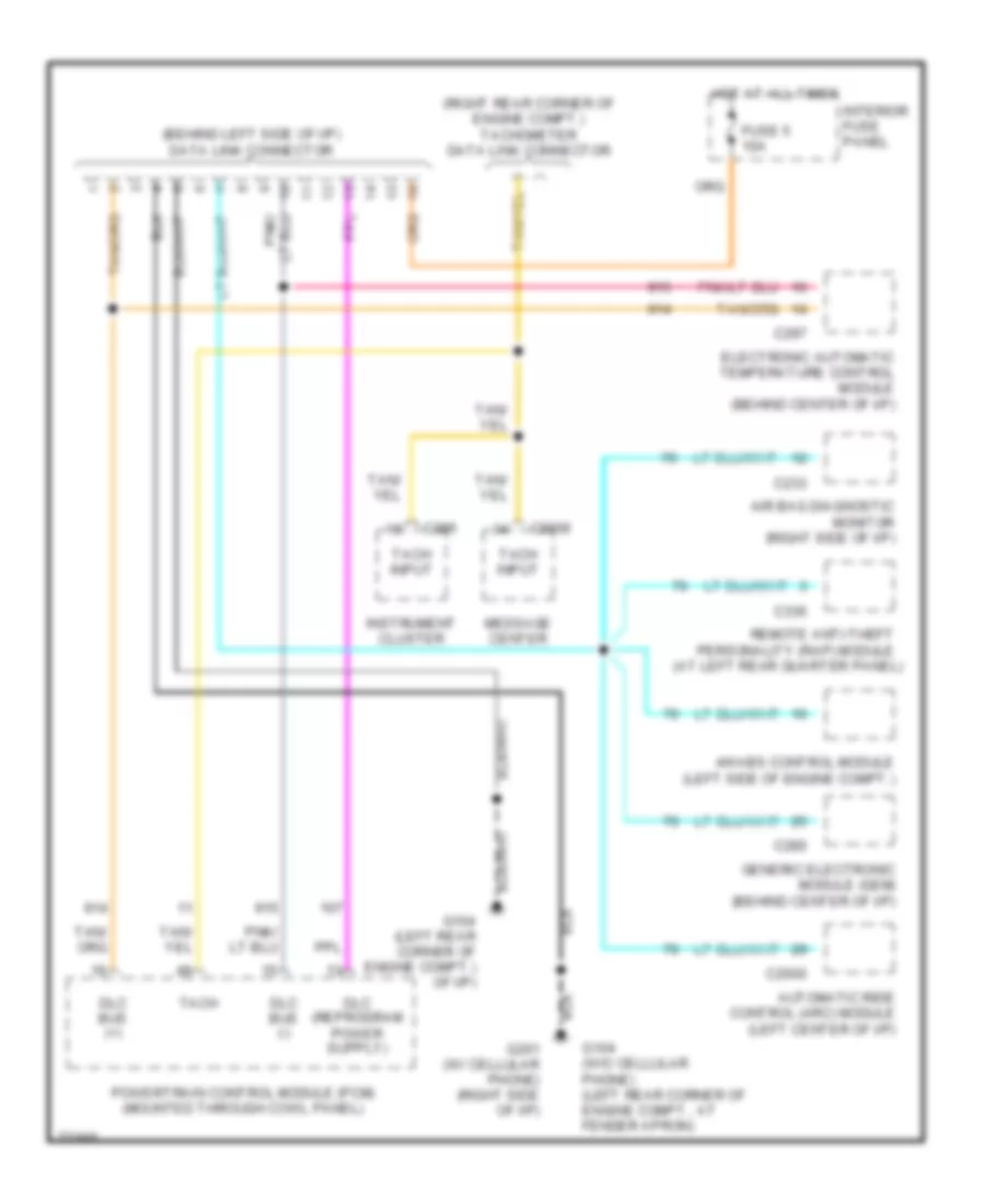
Электросхема компьютерной линии передачи данных CAN для Ford Explorer 1996
Электросхема компьютерной линии передачи данных CAN для Ford Explorer 1996 - Список элементов:
- (at left rear quarter panel)
- (behind left side of i/p) data link connector
- (right rear corner of engine compt.) tachometer data link connector
- 4wabs control module (left side of engine compt.)
- Air bag diagnostic monitor (right side of i/p)
- Automatic ride control (arc) module (left center of i/p)
- C2000
- C2009
- C233
- C280
- C286
- C297
- C336
- Dlc bus (+)
- Dlc bus (-)
- Electronic automatic temperature control module (behind center of i/p)
- Fuse 5 10a
- G104 (left rear corner of engine compt.) of i/p)
- G104 (w/o cellular phone) (left rear corner of engine compt., at fender apron)
- G201 (w/ cellular phone) (right side of i/p)
- Generic electronic module (gem) (behind center of i/p)
- Hot at all times
- Instrument cluster
- Interior fuse panel
- Message center
- Powertrain control module (pcm) (mounted through cowl panel)
- Remote anti-theft personality (rap) module
- Tach
- Tach input
СИСТЕМА УПРАВЛЕНИЯ ДВИГАТЕЛЯ
4.0L
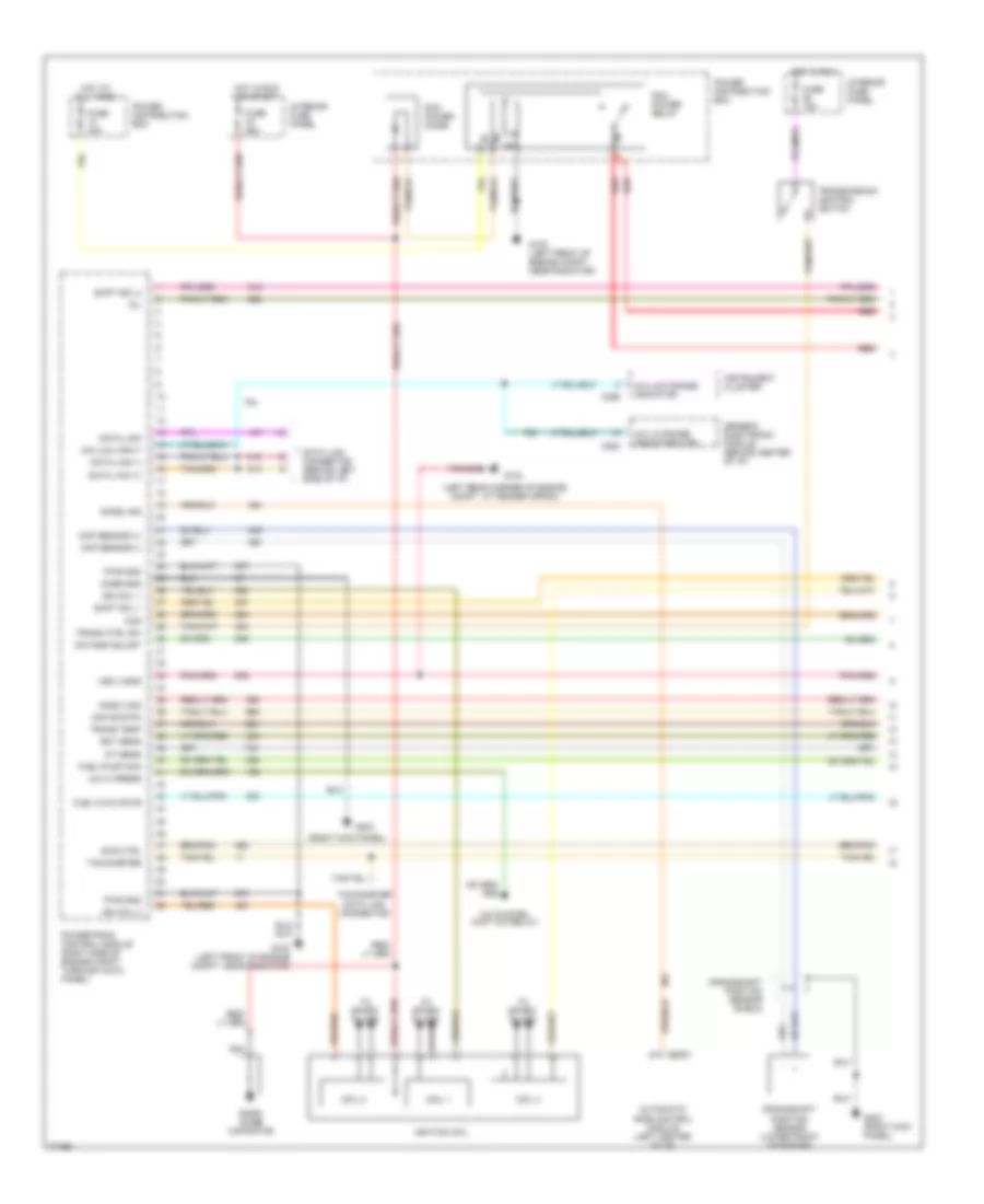
4.0L, Электросхема системы управления двигателя (1 из 4) для Ford Explorer 1996
4.0L, Электросхема системы управления двигателя (1 из 4) для Ford Explorer 1996 - Список элементов:
- (left rear corner of engine compt. at fender apron)
- (right kick panel)
- 4x4 lo range indicator ctrl
- 4x4 low input
- 4x4 low range indicator
- A/c hi press
- A/c system (wot a/c relay)
- Accel sig
- Automatic ride control module (left center of i/p)
- C2001
- C282
- C286
- Case gnd
- Ccs
- Ckp sensor (+)
- Ckp sensor (-)
- Coil 1
- Coil 2
- Coil 3
- Crankshaft position sensor (lower front of engine)
- Crankshaft position sensor shield
- Data link
- Data link (+)
- Data link (-)
- Data link connector (behind left side of i/p)
- Ect sens
- Evr ctrl
- Fuel flow rate
- Fuel pump mon
- Fuse 10a
- Fuse 25a
- Fuse 30a
- G100 (left front of engine compt. near radiator)
- G104
- G203
- G203 (right kick panel)
- Generic electronic module (behind center of i/p)
- Ho2s 3 sig
- Hot at all times
- Hot in run
- Hot in run or start
- Iat sens
- Ign coil 1
- Ign coil 2
- Ignition coil
- Instrument cluster
- Interior fuse panel
- Maf sig rtn
- Mil
- Nca
- Octane adjust
- Pcm power diode
- Pcm power relay
- Power distribution box
- Powertrain control module (right side of engine compt, through cowl panel)
- Pwr gnd
- Radio noise capacitor
- Red
- Shift sol 1
- Shift sol 2
- Tachometer
- Tachometer data link connector
- To spark plugs
- Trans ctrl sw
- Trans temp
- Transmission control switch
- Vss (-)/gnd
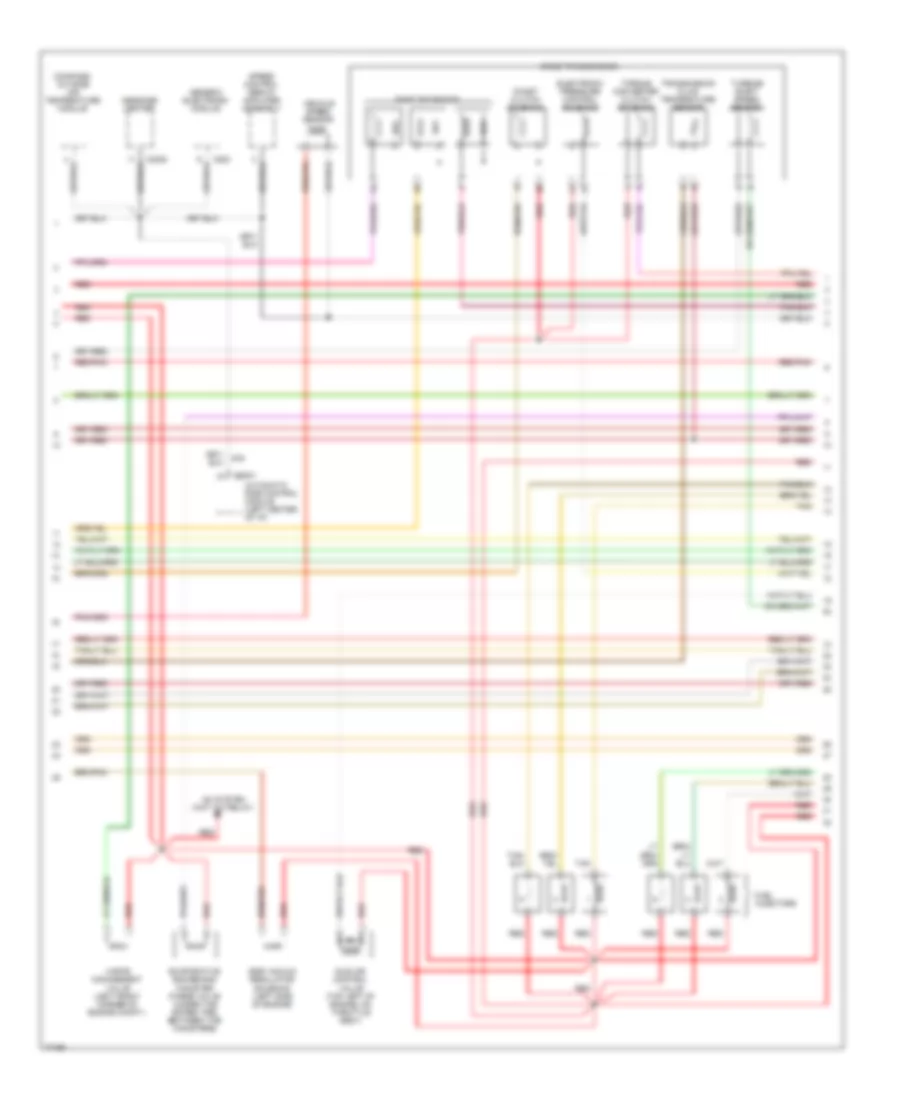
4.0L, Электросхема системы управления двигателя (2 из 4) для Ford Explorer 1996
4.0L, Электросхема системы управления двигателя (2 из 4) для Ford Explorer 1996 - Список элементов:
- (at tank, front) of rear axle) fuel tank assembly
- (behind right kick panel) inertia fuel shut-off switch
- (speedometer/ odometer) vehicle speed input
- C2008
- C2009
- C286
- C287
- C288
- Differential pressure feedback egr sensor (rear of engine compt.)
- Engine coolant temperature sensor (top front of engine)
- Fuel flow rate input
- Fuel pump relay
- Fuel reset switch indicator input
- Fuel tank assembly
- Fuse 20a
- G200 (left kick panel)
- Hot at all times
- Instrument cluster
- Intake air temperature sensor (on intake manifold)
- Malfunction indicator input
- Message center
- Nca
- Octane adjust plug (right rear corner of engine compt.)
- Power distribution box
- Pressure transducer
- Red
- Red/pnk
- Tach input
- Tachometer input
- Throttle position sensor (on throttle body)
- Transmission control indicator input
4.0L, Электросхема системы управления двигателя (3 из 4) для Ford Explorer 1996
4.0L, Электросхема системы управления двигателя (3 из 4) для Ford Explorer 1996 - Список элементов:
- 4r55e transmission
- A/c system (wot a/c relay)
- Automatic ride control module (left center of i/p)
- C2001
- C2008
- C283
- Coast clutch solenoid
- Compass/ outside air temperature module
- Egr vacuum regulator solenoid (left side of engine)
- Electronic pressure control solenoid
- Evaporative emmissions canister purge valve (under the spare tire, between the canisters)
- Fuel injectors
- Generic electronic module
- Idle air control valve (top left of engine, on throttle body)
- Message center
- Red
- Red/pnk
- Shift solenoids
- Speed control servo/ amplifier assembly
- Ss1
- Ss2
- Ss3
- Tan
- Torque converter clutch solenoid
- Transmission fluid temperature sensor
- Turbine shaft speed sensor
- Vapor management valve (left front corner of engine compt.)
- Vehicle speed sensor
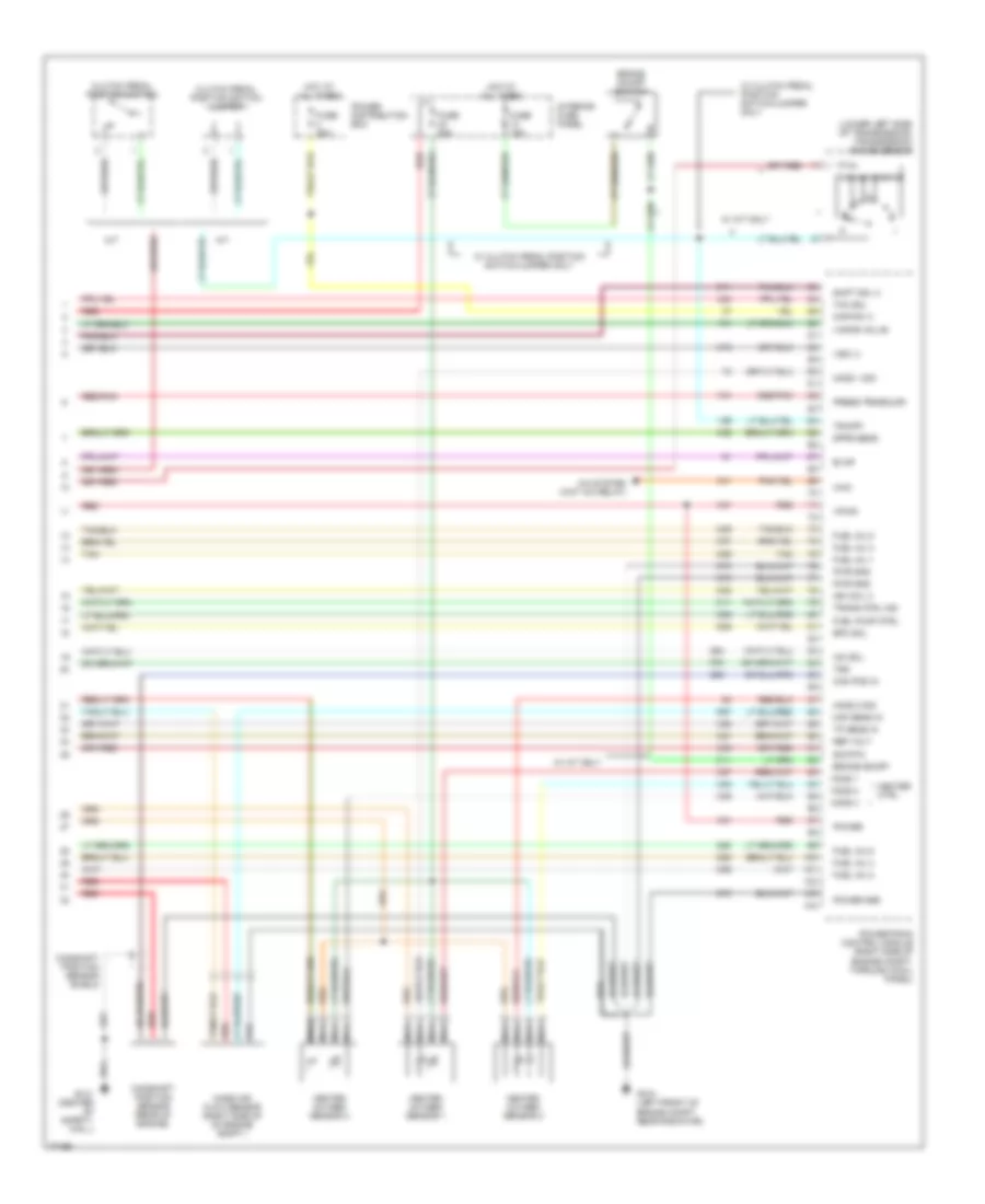
4.0L, Электросхема системы управления двигателя (4 из 4) для Ford Explorer 1996
4.0L, Электросхема системы управления двигателя (4 из 4) для Ford Explorer 1996 - Список элементов:
- (lower left side of transmission) transmission range sensor
- A/c system (wot a/c relay)
- A/t
- Brake on/off
- Brake on/off switch
- Cam pos in
- Camshaft position sensor (rear of engine)
- Camshaft position sensor shield
- Clutch pedal position switch
- Clutch pedal position switch jumper
- Dpfe sens
- Epc sol
- Evap
- Fuel inj 1
- Fuel inj 2
- Fuel inj 3
- Fuel inj 4
- Fuel inj 5
- Fuel inj 6
- Fuel pump ctrl
- Fuse 15a
- Fuse 20a
- G100 (left front of engine compt. near radiator)
- G121 (center of safety wall)
- Heated oxygen sensor 1
- Heated oxygen sensor 2
- Heated oxygen sensor 3
- Heater ctrl
- Ho2s 1
- Ho2s 1 sig
- Ho2s 2
- Ho2s 2 sig
- Ho2s 3
- Hot at all times
- Iac sol
- Ign coil 3
- Interior fuse panel
- Kapwr (+)
- M/t
- Maf sens in
- Mass air flow sensor (right side of of engine compt.)
- Nca
- Power
- Power distribution box
- Power gnd
- Powertrain control module (right side of engine compt, through cowl panel)
- Press trnsducr
- Pwr gnd
- Red
- Red/pnk
- Ref volt
- Shift sol 3
- Sig rtn
- Tan
- Tcc sol
- Tp sens in
- Tr/cpp
- Trans ctrl ind
- Tss
- Vapor valve
- Vpwr
- Vss (+)
- W/ a/t only
- W/ clutch pedal position switch/jumper only
- Wac
5.0L
5.0L, Электросхема системы управления двигателя (1 из 4) для Ford Explorer 1996
5.0L, Электросхема системы управления двигателя (1 из 4) для Ford Explorer 1996 - Список элементов:
- (left rear corner of engine compt. at fender apron)
- (not used)
- (right kick panel)
- A/c hi press
- Air conditioning system (wot a/c relay)
- Case gnd
- Ckp sensor (+)
- Ckp sensor (-)
- Coil 1
- Coil 2
- Coil 3
- Coil 4
- Crankshaft position sensor (lower front of engine)
- Crankshaft position sensor shield
- Data link
- Data link (+)
- Data link (-)
- Data link connector (behind left side of i/p)
- Ect sens
- Evr ctrl
- Fuel flow rate
- Fuel pump mon
- Fuse 10a
- Fuse 25a
- Fuse 30a
- G100 (left front of engine compt. near radiator)
- G104
- G203
- G203 (right kick panel)
- Ho2s 3 sig
- Hot at all times
- Hot in run
- Hot in run or start
- Iat sens
- Ign coil 1
- Ign coil 2
- Interior fuse panel
- Left ignition coil
- Maf sig rtn
- Mil
- Nca
- Octane adjust
- Pcm power diode
- Pcm power relay
- Power distribution box
- Powertrain control module (right side of engine compt, through cowl panel)
- Pwr gnd
- Radio noise capacitor
- Red
- Right ignition coil
- Shift sol 1
- Shift sol 2
- Tachometer
- Tachometer data link connector
- To spark plugs
- Trans ctrl sw
- Trans temp
- Transmission control switch
- Vss (-)/gnd
5.0L, Электросхема системы управления двигателя (2 из 4) для Ford Explorer 1996
5.0L, Электросхема системы управления двигателя (2 из 4) для Ford Explorer 1996 - Список элементов:
- (at tank, front) of rear axle) fuel tank assembly
- (behind right kick panel) inertia fuel shut-off switch
- (speedometer/ odometer) vehicle speed input
- C2008
- C2009
- C286
- C287
- C288
- Egr valve position sensor (right rear of engine)
- Engine coolant temperature sensor (top front of engine)
- Fuel flow rate input
- Fuel pump
- Fuel pump relay
- Fuel reset switch indicator input
- Fuel tank assembly
- Fuse 20a
- G200 (left kick panel)
- Hot at all times
- Instrument cluster
- Intake air temperature sensor (downstream of cleaner assembly)
- Malfunction indicator input
- Message center
- Nca
- Octane adjust plug (top left front of engine compt.)
- Output shaft speed sensor (left rear of transmission)
- Power distribution box
- Pressure transducer
- Red
- Red/pnk
- Tach input
- Tachometer input
- Throttle position sensor (on throttle body)
- Transmission control indicator input
5.0L, Электросхема системы управления двигателя (3 из 4) для Ford Explorer 1996
5.0L, Электросхема системы управления двигателя (3 из 4) для Ford Explorer 1996 - Список элементов:
- 4r70w transmission
- Air conditioning system (wot a/c relay)
- C2008
- C283
- Compass/ outside air temperature module
- Egr vacuum regulator solenoid (top right of engine)
- Electronic pressure control solenoid
- Evaporative emmissions canister purge valve (under the spare tire, between the canisters)
- Fuel injectors
- Generic electronic module
- Idle air control valve (top right of engine, on throttle body)
- Message center
- Red
- Red/pnk
- Shift solenoids
- Speed control servo/ amplifier assembly
- Ss1
- Ss2
- Tan
- Tan/ red
- Tan/red
- Torque converter clutch solenoid
- Transmission fluid temperature sensor
- Vapor management valve (left front corner of engine compt.)
- Vehicle speed sensor
5.0L, Электросхема системы управления двигателя (4 из 4) для Ford Explorer 1996
5.0L, Электросхема системы управления двигателя (4 из 4) для Ford Explorer 1996 - Список элементов:
- (lower left side of transmission) transmission range sensor
- Air conditioning system (wot a/c relay)
- Brake on/off
- Brake on/off switch
- Cam pos in
- Camshaft position sensor (top front of engine)
- Camshaft position sensor shield
- Clutch pedal position switch jumper
- Epc sol
- Evap
- Evp sens
- Fuel inj 1
- Fuel inj 2
- Fuel inj 3
- Fuel inj 4
- Fuel inj 5
- Fuel inj 6
- Fuel inj 7
- Fuel inj 8
- Fuel pump ctrl
- Fuse 15a
- Fuse 20a
- G100 (left front of engine compt. near radiator)
- G121 (center of safety wall)
- Heated oxygen sensor 1
- Heated oxygen sensor 2
- Heated oxygen sensor 3
- Heated oxygen sensor 4
- Heater ctrl
- Ho2s 1
- Ho2s 1 sig
- Ho2s 2
- Ho2s 2 sig
- Ho2s 3
- Ho2s 4
- Ho2s 4 sig
- Hot at all times
- Iac sol
- Ign coil 3
- Ign coil 4
- Interior fuse panel
- Kapwr (+)
- Maf sens in
- Mass air flow sensor (right side of of engine compt.)
- Nca
- Oss (+)
- Power
- Power distribution box
- Power gnd
- Powertrain control module (right side of engine compt, through cowl panel)
- Press trnsducr
- Pwr gnd
- Red
- Red/pnk
- Ref volt
- Sig rtn
- Tan
- Tan/red
- Tcc sol
- Tp sens in
- Tr sens
- Trans ctrl ind
- Vapor valve
- Vpwr
- Vss (+)
- Wac
Система Фар
Электросхема фар, С автолампы для Ford Explorer 1996
Электросхема фар, С автолампы для Ford Explorer 1996 - Список элементов:
- C210
- C280
- C287
- C338
- C350
- Day/night mirror/ autolamp sensor (mounted in rear view mirror)
- Day/nt mir out
- Dimmer relay
- Dimmer switch
- Exterior lights system
- Flash-to- pass switch
- Fuse 10a
- Fuse 15a
- Fuse 20a
- Fuse 30a
- Fuse 7.5a
- G104 (left rear corner of engine compartment, at fender apron)
- G104 (w/o cellular phone) (left rear corner of engine compt., at fender apron)
- G105 (right side of engine compartment)
- G200 (left kick panel)
- G201 (w/ cellular phone) (right side of i/p)
- Generic electronic module (gem) (behind center of i/p)
- Ground
- Head
- Headlamp relay
- Headlamp switch
- Headlamps circuit (w/ drl) (daytime running lamps module pin 6)
- Headlamps circuit (w/ drl) (daytime running lamps module pin 8)
- Headlamps/ fog lamps circuit
- Hi beam indicator
- Hot at all times
- Hot at all times interior fuse panel
- Hot at all times power distribution box
- Hot in start or run
- Ignition
- Instrument cluster
- Interior fuse panel
- Lamp out warning module (in instrument panel console)
- Left headlamp
- Memory seat module (below left front seat)
- Mirrors system (automatic day/night miror)
- Multi- function switch
- Off
- Park
- Park lamp relay
- Pass
- Power
- Relay module (behind center of i/p)
- Relay output
- Remote anti-theft personality (rap) module (at left rear quarter panel)
- Right headlamp
- W/ drl
- W/ lamp out warning
- W/ memory seat
- W/o drl
- W/o lamp out warning
- W/o memory seat
Электросхема фар, С DRL для Ford Explorer 1996
Электросхема фар, С DRL для Ford Explorer 1996 - Список элементов:
- Acc
- Battery
- Brake fluid level warning switch (mounted on left side of master cylinder)
- Brake indicator
- C210
- C287
- C288
- Daytime running lamps (drl) module (left front corner of engine compt.)
- Dimmer switch
- Drl disable
- Flash-to- pass switch
- Fuse 11 20a
- Fuse 11 7.5a
- Fuse 15 15a
- Fuse 26 10a
- Fuse 33 15a
- Fuse 4 10a
- Fuse 8 10a
- G104 (left rear corner of engine compartment, at fender apron)
- G104 (w/o cellular phone) (w/o cellular phone) (left rear corner of (left rear corner of engine compt., at engine compt., at fender apron) fender apron)
- G105 (right side of engine compartment)
- G201 (w/ cellular phone) (right side of i/p)
- Head
- Headlamp switch
- Headlamps
- Headlamps circuit (w/ autolamps)
- Headlamps/ fog lamps circuit (fog lamp relay)
- Hi beam ind feed
- Hi beam indicator
- Hot at all times
- Hot in run
- Hot in run or start
- Ign feed
- Ignition switch
- Instrument cluster
- Interior fuse panel
- Lamp out warning module (in instrument panel console)
- Left headlamp
- Lock
- Low
- Multi- function switch
- Normal
- Off
- Park
- Parking brake switch (right side of parking brake lever)
- Pass
- Power distribution box
- Right headlamp
- Run
- Start
- W/ lamp out warning
- W/o lamp out warning
Электросхема фар и противотуманных фар для Ford Explorer 1996
Электросхема фар и противотуманных фар для Ford Explorer 1996 - Список элементов:
- (not used)
- C210
- C287
- Dimmer switch
- Flash-to- pass
- Fog lamp relay
- Fog lamp switch
- Fuse 15a
- Fuse 20a
- Fuse 33 15a
- Fuse 4 10a
- Fuse 8 10a
- G104 (left rear corner of engine compartment, at fender apron)
- G104 (w/o cellular phone) (left rear corner of engine compt., at fender apron)
- G105 (right side of engine compartment)
- G105 (right side of engine compartment)
- G201 (w/ cellular phone) (right side of i/p)
- Head
- Headlamp switch
- Hi beam indicator
- Hot at all times
- Illum
- Instrument cluster
- Interior fuse panel
- Interior lights system
- Lamp out warning module (in instrument panel console)
- Left fog lamp
- Left headlamp
- Multi- function switch
- Off
- Park
- Pass
- Power distribution box
- Right fog lamp
- Right headlamp
- W/ fog lamps only
- W/ lamp out warning
- W/o lamp out warning
СИСТЕМЫ ПАМЯТИ
Электросхема памяти сидений Левого фронта для Ford Explorer 1996
Электросхема памяти сидений Левого фронта для Ford Explorer 1996 - Список элементов:
- (at left rear quarter panel)
- C335
- C338
- C350
- C351
- C352
- Entire seat
- Front height motor
- Front mtr-l
- Front of seat
- Front sensor
- Fuse 28 7.5a
- Fuse 5 30a
- Fuse 9 10a
- Fwd
- Fwd/ rwd motor
- G100 (left front of engine compt, near radiator)
- G200 (left kick panel)
- Ground
- Hall effect sensor
- Horizontal mtr-l
- Horizontal sensor
- Hot at all times
- Hot in start
- Interior fuse panel
- Left front power seat control switch
- Left front seat motor assembly
- Mem 1
- Mem 2
- Mem seat sw enable
- Mem seat sw lp drive
- Mem seat sw lp enable
- Mem seat sw postn #1
- Mem seat sw postn #2
- Mem seat sw set
- Memory seat module (below left front seat)
- Memory seat switch
- Nca
- Personality (rap) module
- Power
- Power distribution box
- Rear height motor
- Rear mtr-l
- Rear of seat
- Rear sensor
- Remote anti-theft
- Rwd
- S209
- S234
- S303
- S317
- S321
- Seats system (left power lumbar seat switch)
- Sensor +
- Sensor -
- Set
- Start
Электросхема памяти для Ford Explorer 1996
Электросхема памяти для Ford Explorer 1996 - Список элементов:
- (at left rear quarter panel)
- C335
- C338
- C350
- C351
- C352
- Entire seat
- Front height motor
- Front mtr-l
- Front of seat
- Front sensor
- Fuse 28 7.5a
- Fuse 5 30a
- Fuse 9 10a
- Fwd
- Fwd/ rwd motor
- G100 (left front of engine compt, near radiator)
- G200 (left kick panel)
- Ground
- Hall effect sensor
- Horizontal mtr-l
- Horizontal sensor
- Hot at all times
- Hot in start
- Interior fuse panel
- Left front power seat control switch
- Left front seat motor assembly
- Mem 1
- Mem 2
- Mem seat sw enable
- Mem seat sw lp drive
- Mem seat sw lp enable
- Mem seat sw postn #1
- Mem seat sw postn #2
- Mem seat sw set
- Memory seat module (below left front seat)
- Memory seat switch
- Nca
- Personality (rap) module
- Power
- Power distribution box
- Rear height motor
- Rear mtr-l
- Rear of seat
- Rear sensor
- Remote anti-theft
- Rwd
- S209
- S234
- S303
- S317
- S321
- Seats system (left power lumbar seat switch)
- Sensor +
- Sensor -
- Set
- Start
СИСТЕМЫ ПОДВЕСКИ
Электросхема электроники подвески (1 из 2) для Ford Explorer 1996
Электросхема электроники подвески (1 из 2) для Ford Explorer 1996 - Список элементов:
- (left rear corner of engine compartment, on fender apron)
- 4x4 high sig
- 4x4 low sig
- Arc accel sig
- Arc compr rly
- Arc off/on sw
- Automatic ride control (arc) module (left center of i/p)
- Automatic ride control compressor assembly (at rear of vehicle)
- Automatic ride control off/on switch (rear of vehicle)
- Automatic ride control relay
- Auxiliary relay box #3 (left rear of engine compartment)
- Brake on/off sw
- C2000
- C2001
- Comp vent sol
- Door ajar in
- Engine controls system
- Front fill sol
- Frt & rr gate sol
- Fuse 18 15a
- Fuse 3 50a
- G100 (w/o cellular phone) (left rear corner of engine compt.)
- G104
- G104 (left rear corner of engine compt, at fender apron)
- G105 (right side of engine compt)
- G1oo (left front of engine compt, near radiator)
- G200 (left kick panel)
- G201 (w/ cellular phone) (right side of i/p)
- Gnd
- Height sen power
- Hot at all times
- Iso link
- Left front shock actuator (at left front shock)
- Left rear shock actuator (at left rear shock)
- Lf height sen
- Lf shock actuator
- Lf shock pos fb
- Lr shock actuator
- Lr shock pos fb
- Nca
- Pcm accel sig
- Pnk
- Power (hot in run)
- Power distribution box
- Powertrain control module (pcm) (right rear of engine compt.)
- Rear fill sol
- Rear height sen
- Red
- Rf shock actuator
- Rf shock pos fb
- Right front shock actuator (at right front shock)
- Right rear shock actuator (at right rear shock)
- Rr shock actuator
- Rr shock pos fb
- Steering sen a
- Steering sen b
- Steering sensor (in steering column)
- Vehicle speed sensor (on transmission)
- Vss (+)
- Warning sig
Электросхема электроники подвески (2 из 2) для Ford Explorer 1996
Электросхема электроники подвески (2 из 2) для Ford Explorer 1996 - Список элементов:
- 4wabs control module (left side of engine compt)
- Air bag diagnostic monitor (behind right side of i/p)
- Brake on/off switch (on brake pedal)
- C2008
- C2009
- C233
- C280
- C282
- C336
- Data link connector (behind left side of i/p)
- Front fill solenoid (left rear corner of engine compt)
- Front gate solenoid (near right radiator support)
- Fuse 13 15a
- Fuse 1o 7.5a
- G100 (left front of engine compt, near radiator)
- G105 (right side of engine compt)
- G200 (left kick panel)
- Generic electronic module (gem) (behind center of i/p)
- Hot at all times
- Hot in run
- Interior fuse panel
- Left front height sensor (at left front shock)
- Message center (in instrument panel console)
- Rear fill solenoid (on rear axle)
- Rear gate solenoid (left rear corner of vehicle)
- Rear height sensor (left rear corner of vehicle)
- Remote anti-theft personality (rap) module (left rear quarter panel)
СИСТЕМЫ СИДЕНИЙ
питание и поясничная схема места для Ford Explorer 1996
питание и поясничная схема места для Ford Explorer 1996 - Список элементов:
- Bolster)
- Entire seat
- Front height motor
- Front of seat
- Fuse 5 30a
- Fwd
- Fwd/rwd motor
- G200 (left kick panel)
- Hot at all times
- Left front power seat control switch
- Left front power seat motor assembly
- Left power bolster seat switch
- Left power bolster/ lumbar motor (w/ power bolster)
- Left power lumbar seat switch
- Lumbar motor
- Nca
- Power distribution box
- Rear height motor
- Rear of seat
- Red
- Right front power seat control switch
- Right front power seat motor assembly
- Right power lumbar motor
- Right power lumbar seat switch
- Rwd
- W/ power bolster
Стартер Генератор
Электросхема Генератора для Ford Explorer 1996
Электросхема Генератора для Ford Explorer 1996 - Список элементов:
- 4.0l only
- Acc
- Airbag diagnostic monitor
- Battery
- Battery ground
- C228
- C288
- Charge warning indicator
- Fuse 15 15a
- Fuse 15a
- Fuse 60a
- Generator/ voltage regulator
- Ignition switch
- Instrument cluster
- Interior fuse panel
- Lock
- Off
- Ohms
- Power distribution box
- Red
- Run
- Start
- Starter motor
- Starter relay
Электросхема стартера для Ford Explorer 1996
Электросхема стартера для Ford Explorer 1996 - Список элементов:
- (left side of transmission)
- (not used)
- A/t (w/ center console)
- A/t (w/o center console)
- Acc
- Anti-theft relay (in relay module)
- Battery
- Battery ground
- C338
- Clutch pedal position switch (on clutch pedal arm)
- Clutch pedal position switch jumper (behind left side of i/p, taped to harness)
- Fuse 10a
- Fuse 60a
- Fusible links (charging system)
- Hold
- Ignition switch
- Interior fuse panel
- Interior fuse panel (fuse 34)
- Lock
- M/t
- Off
- Pnk
- Power distribution box
- Pull-in
- Red
- Remote anti-theft personality module (at left rear quarter panel)
- Run
- Sta
- Start
- Starter motor
- Starter relay (left front of engine compartment, at fender apron)
- Transmission range sensor
- W/ rap module
- W/o rap module
Стеклоочистители и Стеклоомыватели Дворники
Электросхема передних стеклоочистителей дворников и омывателя лобового стекла для Ford Explorer 1996
Электросхема передних стеклоочистителей дворников и омывателя лобового стекла для Ford Explorer 1996 - Список элементов:
- (left rear corner of engine compt, at fender apron) g104
- 103k ohms
- 11.3k
- 3.3k ohms
- 4.08k
- Auxiliary relay box #2 (right front of engine compt.)
- Brake/run
- C210
- C280
- Front washer pump motor relay
- Fuse 10a
- Fuse 30a
- G105 (right side of engine compt.)
- Generic electronic module (behind center of i/p)
- Hot in acc or run
- Int max
- Int min
- Interior fuse panel
- Interval delay/wash
- Liftgate wiper/ washer switch
- Multi- function switch
- Off
- Off 47.6k ohms
- Ohms
- Park
- Park sense
- Power distri- bution box (left side of engine compt.)
- Red
- Run
- Signal return (gnd)
- Tan/ red
- Tan/red
- Washer pump
- Washer pump motor
- Washer switch
- Wiper hi-lo relay
- Wiper mode select
- Wiper motor
- Wiper run relay
- Wiper speed
- Wiper switch
Электросхема заднего стеклоочистителя дворника и омывателя для Ford Explorer 1996
Электросхема заднего стеклоочистителя дворника и омывателя для Ford Explorer 1996 - Список элементов:
- 103k ohms
- 110k ohms
- Auxiliary relay box #1 (right front of engine compt.)
- Battery saver relay
- Body computer system
- C280
- C281
- C283
- Disable
- Front washer pump motor relay
- Fuse 10a
- Fuse 15a
- Fuse 30a
- G104 (left rear corner of engine compt., at fender apron)
- G104 (w/o cellular phone) (left rear corner of engine compartment, at fender apron)
- G200 (left kick panel)
- G201 (w/ cellular phone) (right side of i/p)
- G412 (rear of vehicle)
- Generic electronic module (behind i/p, left of steering column)
- Hot at all times
- Hot in acc or run
- Illumination
- Int max
- Int min
- Interior fuse panel
- Interior lights system
- Left liftgate ajar switch
- Liftgate washer pump motor
- Liftgate wiper disable switch
- Liftgate wiper motor
- Liftgate wiper/ washer switch
- Nca
- Off
- Pnk
- Power distribution box
- Rear wiper down relay
- Rear wiper mode select
- Rear wiper up relay
- Relay module (behind center of i/p)
- Return (gnd)
- Right liftgate ajar switch
- Tan
- Washer switch
- Wiper high
- Wiper low
- Wiper park
ЦЕНТРАЛЬНЫЙ ЗАМОК
Электросхема центрального замка для Ford Explorer 1996
Электросхема центрального замка для Ford Explorer 1996 - Список элементов:
- (2 door)
- (4 door)
- 87a
- Auxiliary relay box #4 (left rear of vehicle, above wheelwell)
- C280
- C336
- C338
- Door lock relay
- Door unlock relay
- Driver's door unlock relay
- Fuse 30a
- G200 (left kick panel)
- G500 (left front door)
- G600 (right front door)
- Generic electronic module (behind center of i/p)
- Hot at all times
- Left front door lock motor
- Left front power door lock switch (2 door)
- Left rear door lock motor (4 door)
- Liftgate lock motor
- Liftgate lock switch
- Lock
- Master window/ door lock control switch (4 door)
- Power distribution box (left side of engine compt, at fender apron)
- Remote anti-theft personality module (w/ keyless entry only) (left rear quarter panel)
- Right front door lock motor
- Right front power door lock switch
- Right rear door lock motor (4 door)
- Unlck
- Unlock
- W/ keyless entry
- W/ keyless entry only
- W/o keyless entry