Автомтическая коробка Передач (АКПП) Полная привод (4WD) Блокировка Дифференциала
4.3L
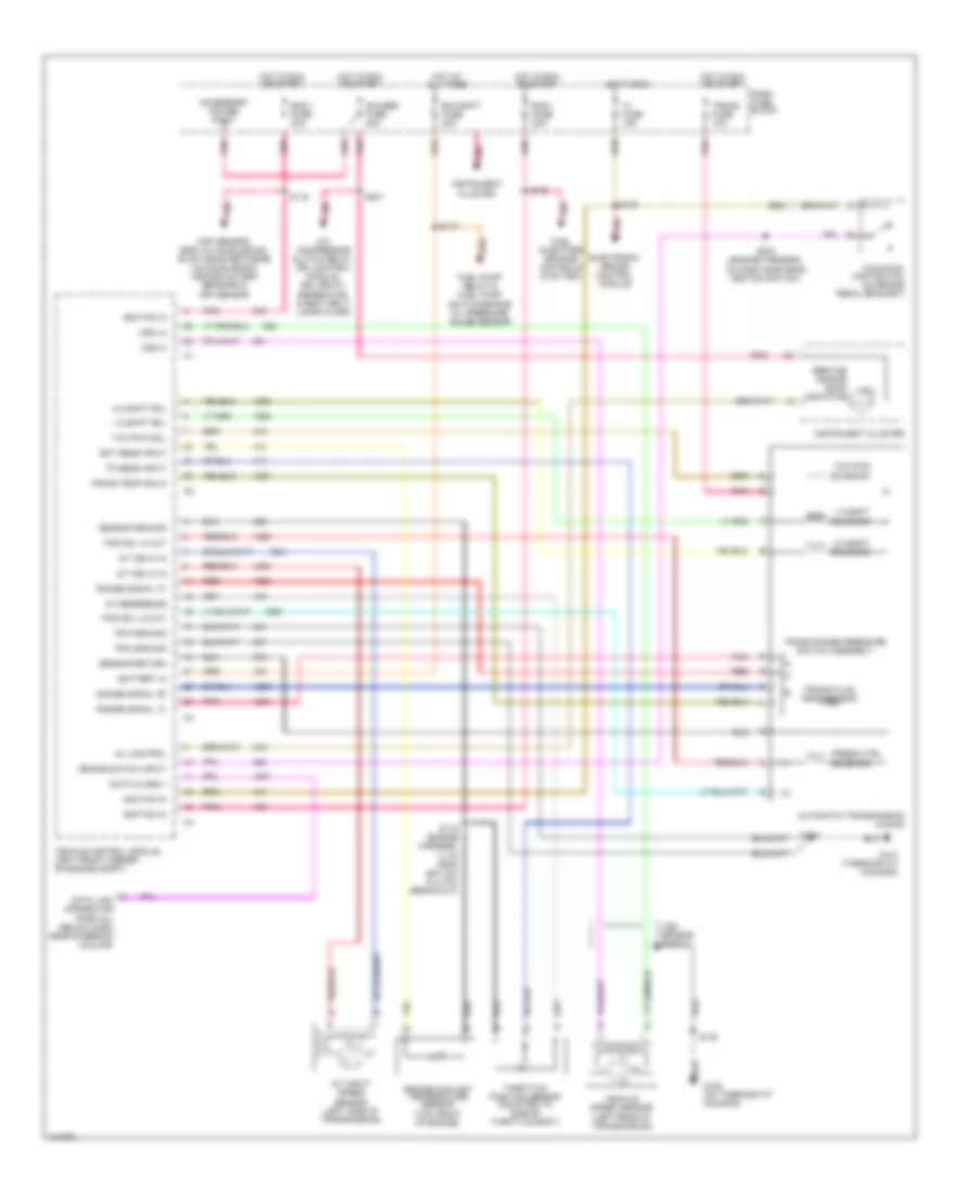
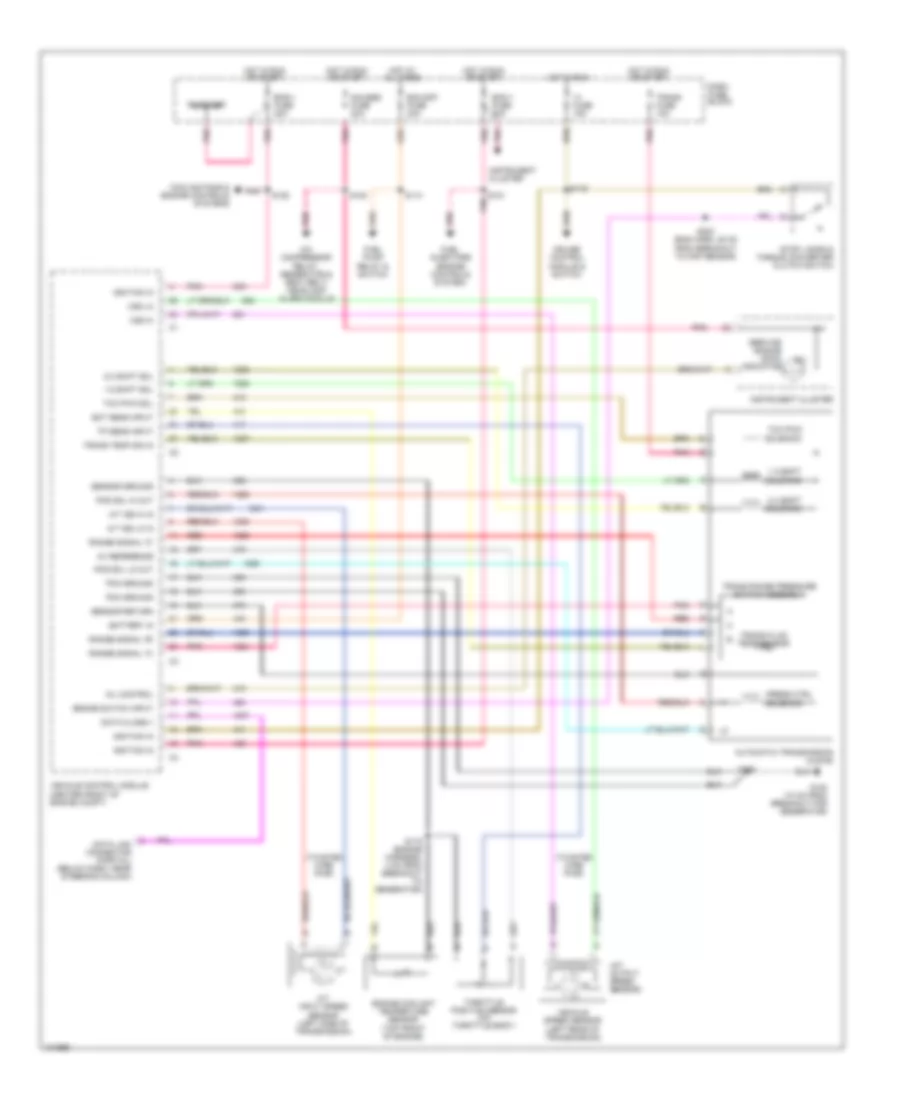
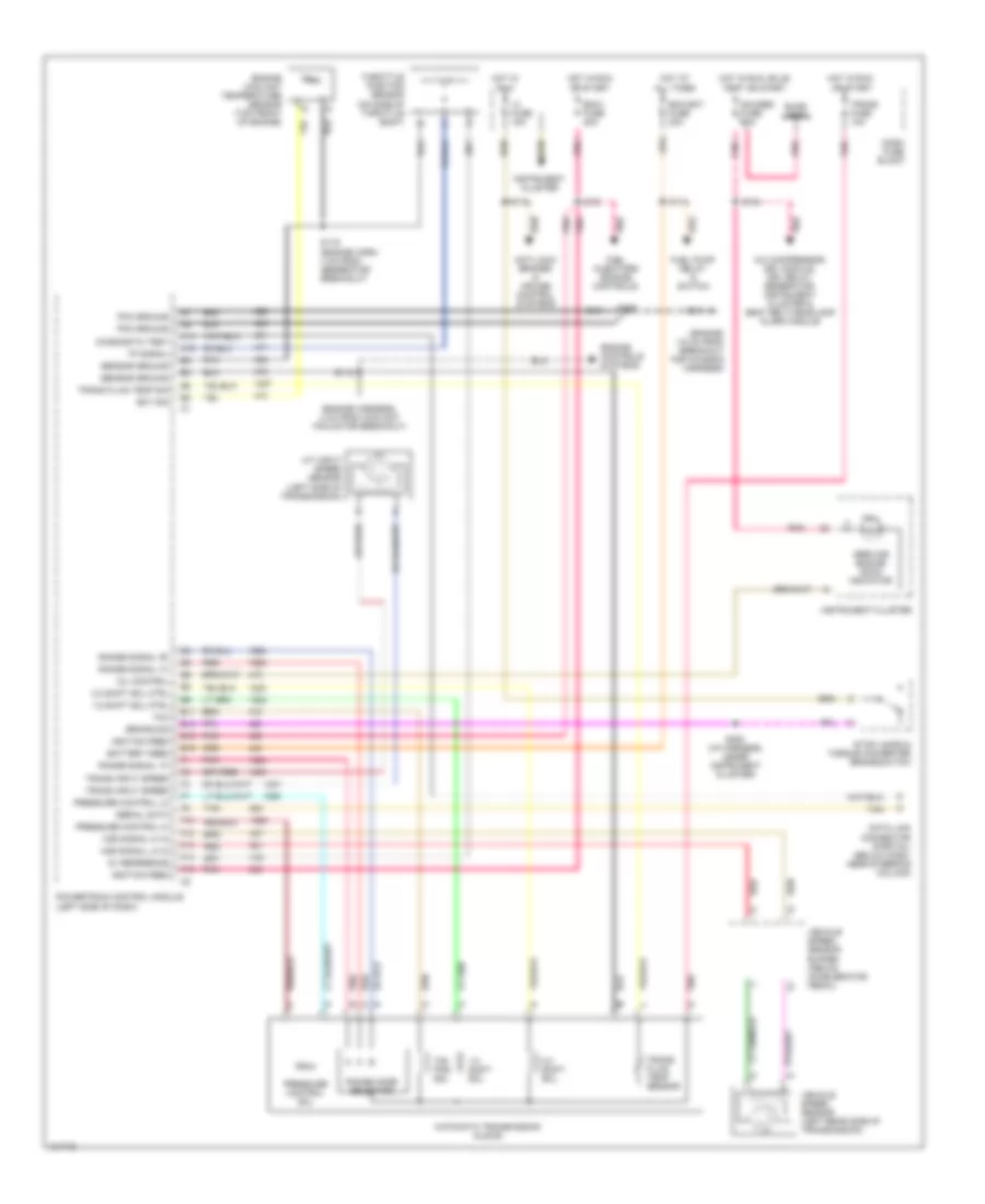
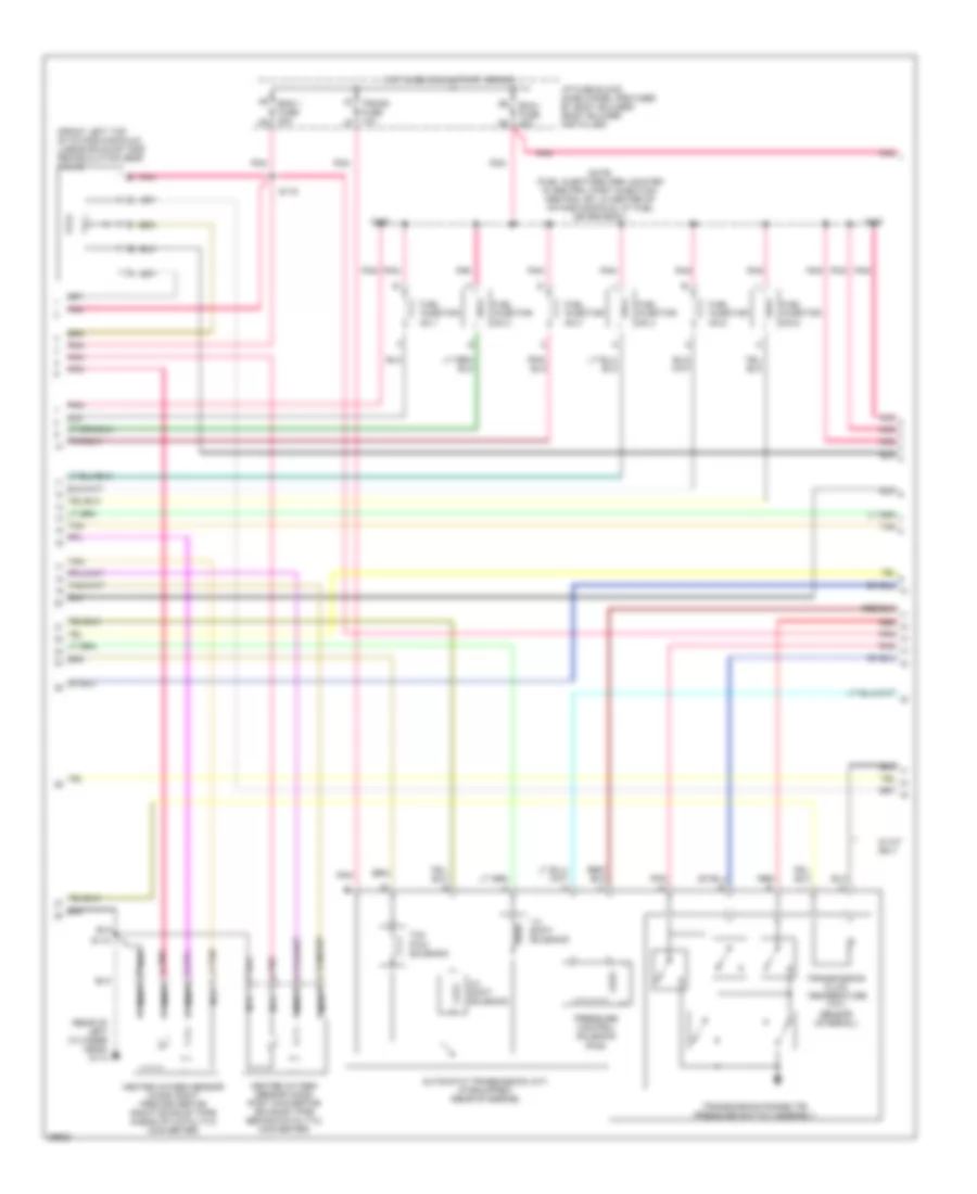
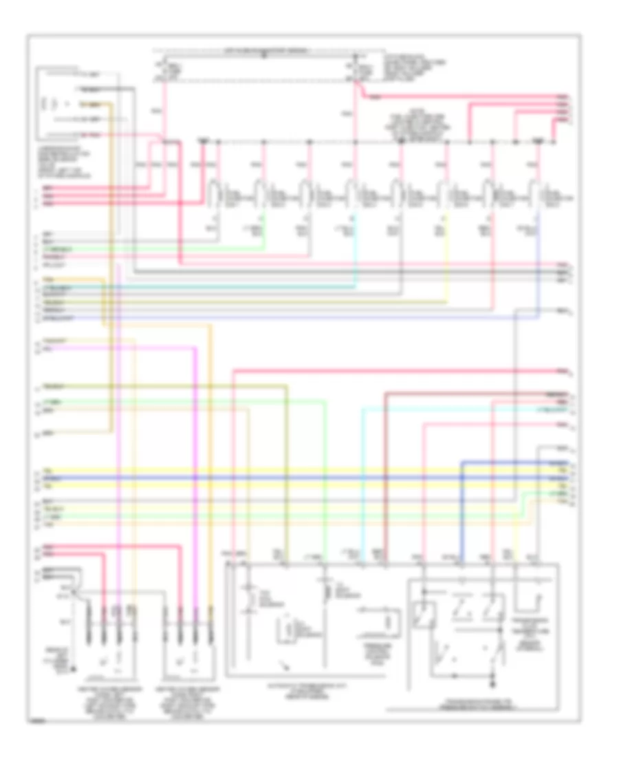
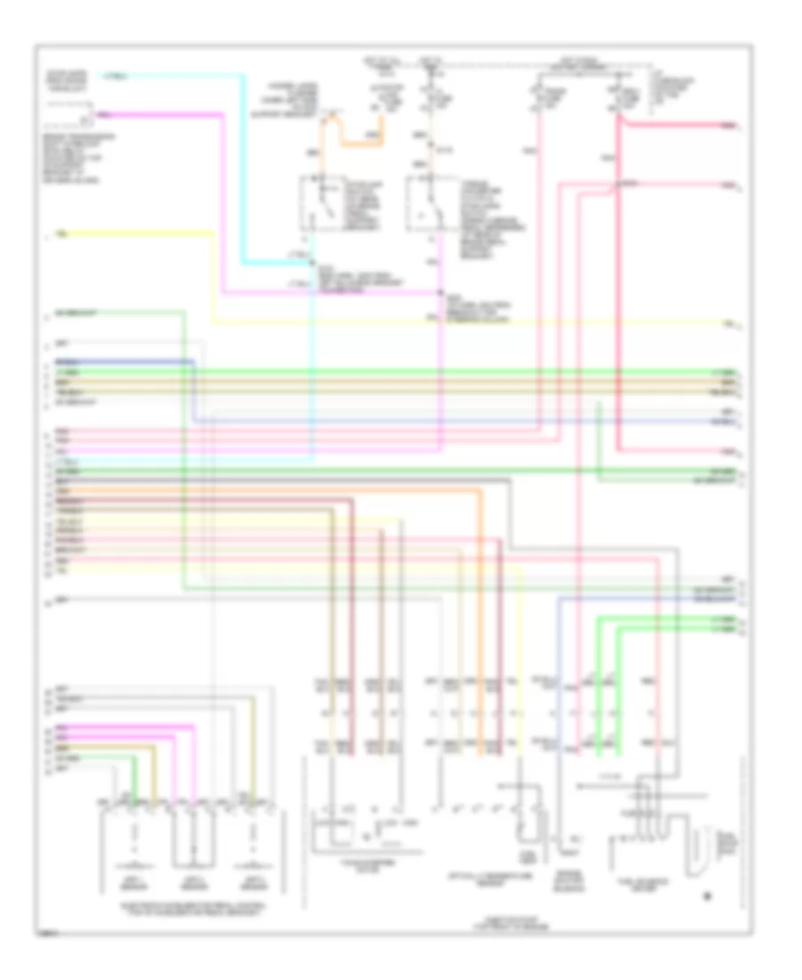
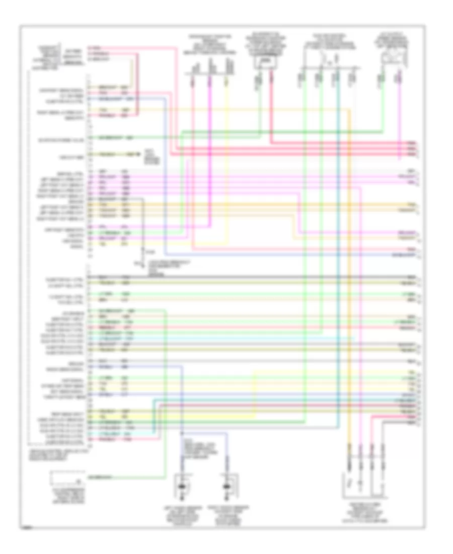
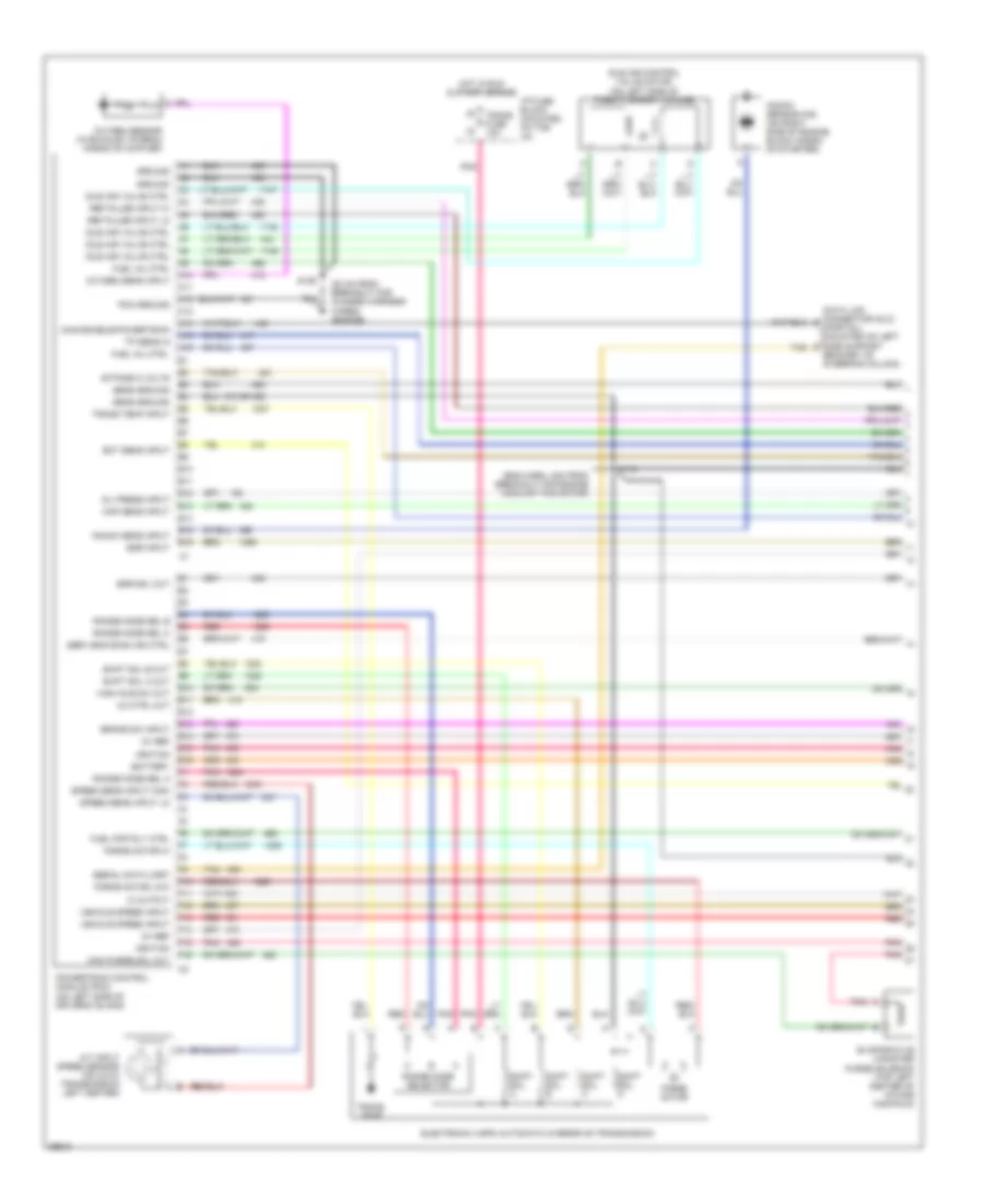
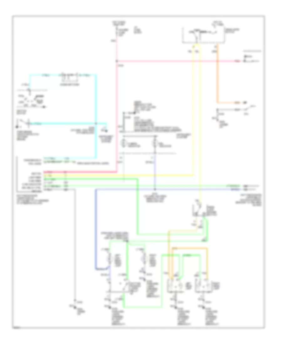
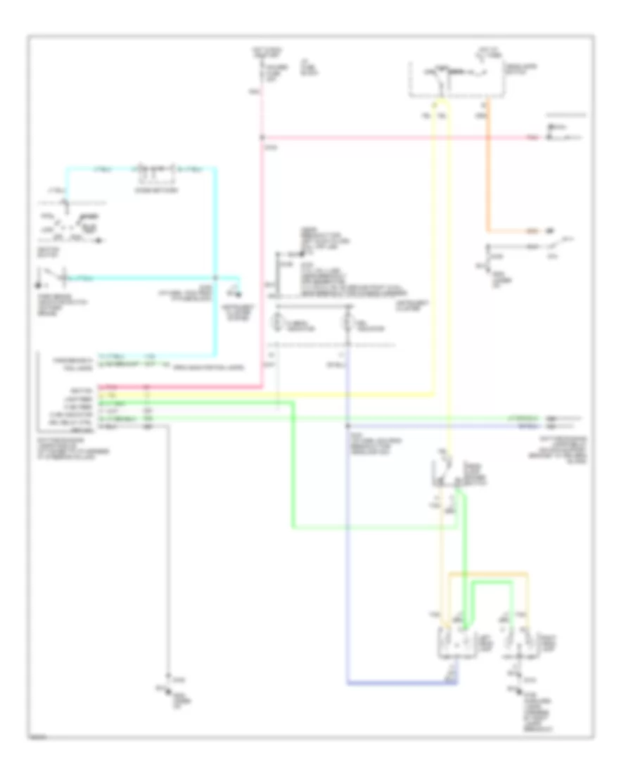
4.3L (VIN W), Электросхема коробки передач АКПП, 4L80-E для GMC Vandura P1997 3500
4.3L (VIN W), Электросхема коробки передач АКПП, 4L80-E для GMC Vandura P1997 3500 - Список элементов:
- (mil)
- 1-2 shift
- 1-2 shift sol
- 2-3 shift sol
- 2-3 shift solenoid
- 5v reference
- A/c compressor clutch relay, drl control module, drl relay, generator, & seat belt/ lamps alarm
- A/t input speed sensor (left side of transmission)
- A/t iss hi in
- A/t iss lo in
- Accessory power point
- Automatic transmission (4l80-e)
- Battery in
- Brake switch input
- Cmp sensor, egr valve solenoid, evap canister purge valve solenoid, heated oxygen sensors & maf sensor
- Dash fuse block
- Data class ii
- Data link connector (partial) (below dash near steering column)
- Ecm batt fuse 20a
- Ecm-i fuse 20a
- Ect sens input
- Electronic brake control module
- Eng 1 fuse 20a
- Engine coolant temperature sensor (top front of engine)
- Fuel injectors (enigine controls sysytem)
- Fuel pump relay & fuel pump switch/engine oil pressure gauge sensor
- G110 (thermostat housing)
- G125 (on thermostat housing)
- Gauges fuse 20a
- Hot at all times
- Hot in run
- Hot in run or start
- I-3 fuse 15a
- Ignition in
- Instrument cluster
- Mil control
- Pcm ground
- Pcs sol hi out
- Pcs sol lo out
- Pnk
- Press ctrl
- Range signal "a"
- Range signal "b"
- Range signal "c"
- Red
- S108
- S116
- S119 (engine harness, 11 cm from ect-a/c clutch break-out)
- S133
- S134
- S138
- S143
- S200 (engine harness, on dash side near ignition switch)
- S207
- Sensor ground
- Sensor return
- Service engine soon indicator
- Solenoid
- Tcc pwm
- Tcc pwm sol
- Tcc/stop- lamp switch (on brake pedal bracket)
- Throttle position sensor (mounted to side of throttle body)
- Tp sens input
- Trans fluid temp sensor
- Trans fuse 10a
- Trans range pressure switch assembly
- Trans temp sig in
- Vehicle control module (left front corner of engine compt)
- Vehicle speed sensor (left rear of transmission)
- Vss hi
- Vss lo
- Vss sensor shield
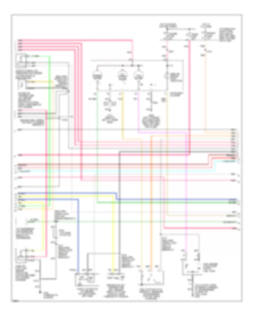
5.7L
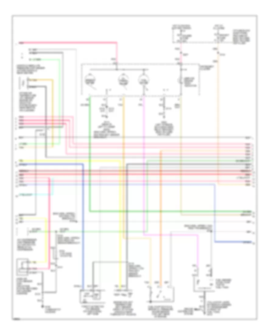
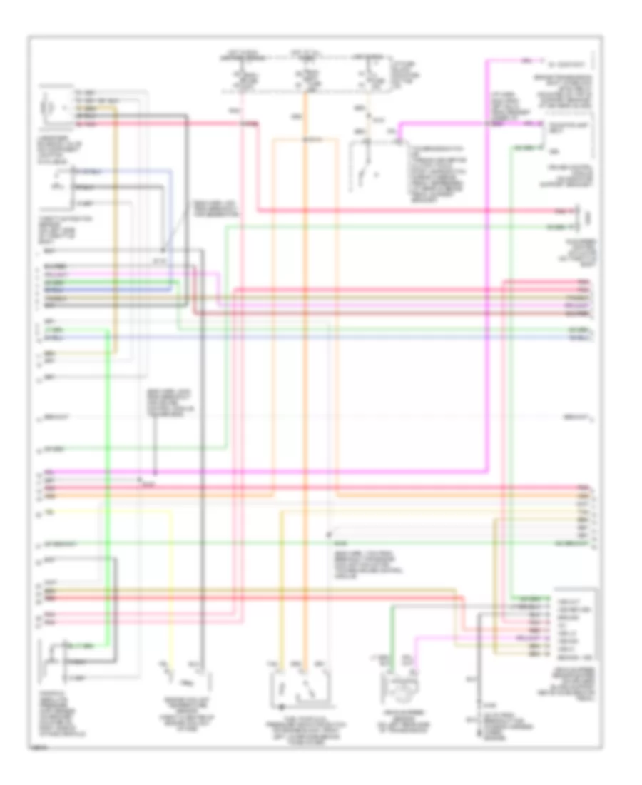
5.7L (VIN R), Электросхема коробки передач АКПП, 4L80-E для GMC Vandura P1997 3500
5.7L (VIN R), Электросхема коробки передач АКПП, 4L80-E для GMC Vandura P1997 3500 - Список элементов:
- (mil)
- 1-2 shift
- 1-2 shift sol
- 2-3 shift sol
- 2-3 shift solenoid
- 5v reference
- A/c compressor clutch relay, drl control module, drl relay, generator, & seat belt/ lamps alarm
- A/t input speed sensor (left side of transmission)
- A/t iss hi in
- A/t iss lo in
- Accessory power point
- Automatic transmission (4l80-e)
- Battery in
- Brake switch input
- Cmp sensor, egr valve solenoid, evap canister purge valve solenoid, heated oxygen sensors & maf sensor
- Dash fuse block
- Data class ii
- Data link connector (partial) (below dash near steering column)
- Ecm batt fuse 20a
- Ecm-i fuse 20a
- Ect sens input
- Electronic brake control module
- Eng 1 fuse 20a
- Engine coolant temperature sensor (top front of engine)
- Fuel injectors (enigine controls sysytem)
- Fuel pump relay & fuel pump switch/engine oil pressure gauge sensor
- G110 (thermostat housing)
- G125 (on thermostat housing)
- Gauges fuse 20a
- Hot at all times
- Hot in run
- Hot in run or start
- I-3 fuse 15a
- Ignition in
- Instrument cluster
- Mil control
- Pcm ground
- Pcs sol hi out
- Pcs sol lo out
- Pnk
- Press ctrl
- Range signal "a"
- Range signal "b"
- Range signal "c"
- Red
- S108
- S116
- S119 (engine harness, 11 cm from ect-a/c clutch break-out)
- S133
- S134
- S138
- S143
- S200 (engine harness, on dash side near ignition switch)
- S207
- Sensor ground
- Sensor return
- Service engine soon indicator
- Solenoid
- Tcc pwm
- Tcc pwm sol
- Tcc/stop- lamp switch (on brake pedal bracket)
- Throttle position sensor (mounted to side of throttle body)
- Tp sens input
- Trans fluid temp sensor
- Trans fuse 10a
- Trans range pressure switch assembly
- Trans temp sig in
- Vehicle control module (left front corner of engine compt)
- Vehicle speed sensor (left rear of transmission)
- Vss hi
- Vss lo
- Vss sensor shield
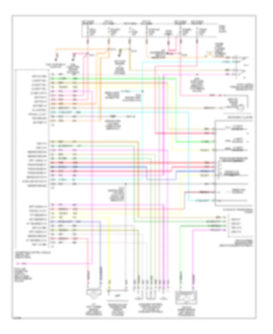
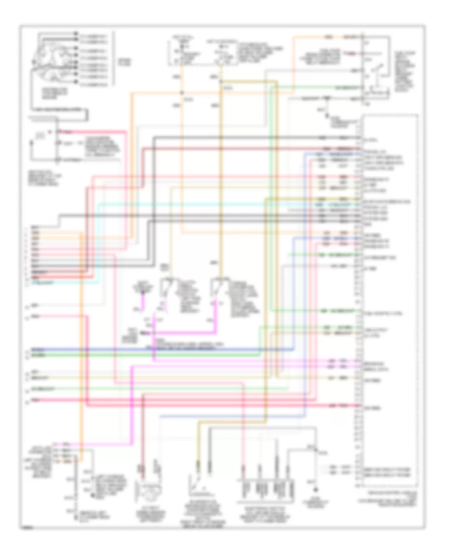
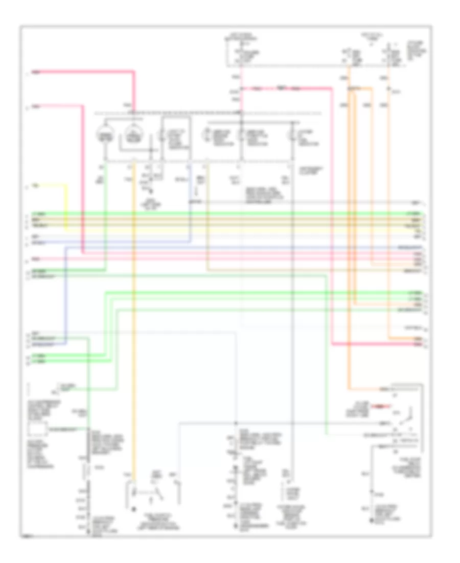
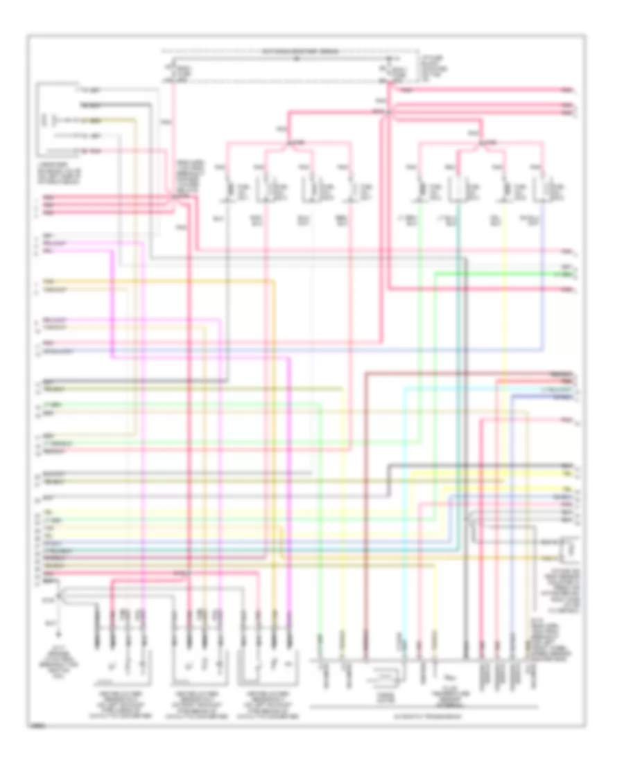
6.5L
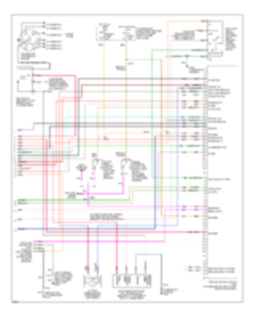
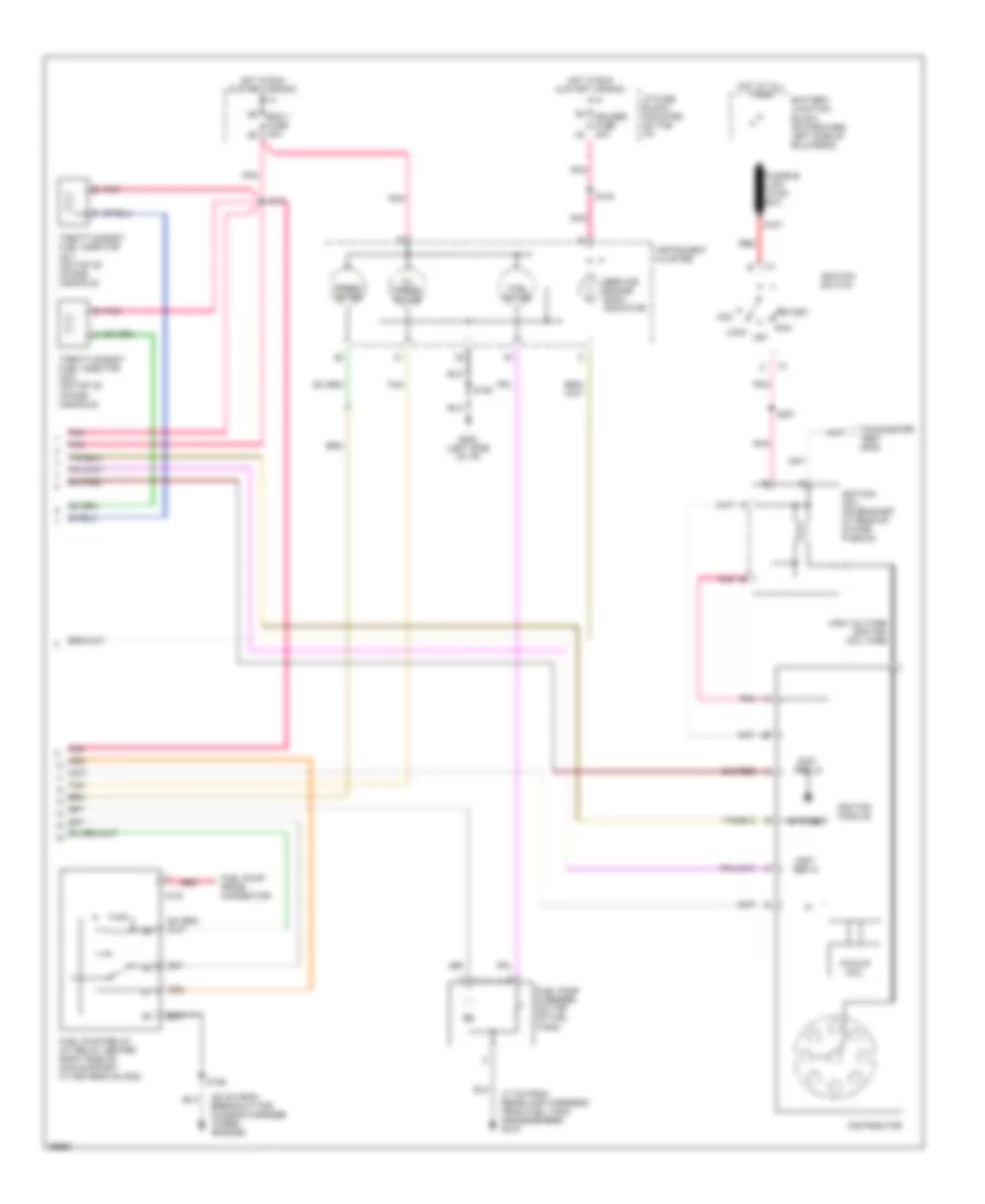
6.5L (VIN F), Электросхема коробки передач АКПП, 4L80-E для GMC Vandura P1997 3500
6.5L (VIN F), Электросхема коробки передач АКПП, 4L80-E для GMC Vandura P1997 3500 - Список элементов:
- (engine harn, 2 cm from wiper motor break-out)
- (rear lamps provision connector)
- 1-2 shift
- 1-2 shift sol
- 2-3 shift sol
- 2-3 shift solenoid
- 3-2 shift
- 3-2 shift sol
- A/c compressor relay & generator
- A/t input speed sensor (left side of transmission)
- A/t iss sens hi in
- A/t iss sens lo in
- A12
- Accelerator pedal position module (attached to accelerator pedal)
- Anti-lock brakes & cruise control systems
- App 1 5v ref
- App 1 signal in
- App 2 5v ref
- App 2 signal in
- App 3 5v ref
- App 3 signal in
- Automatic transmission (4l80-e)
- B10
- B12
- Battery in
- Brake switch in
- Buss bar
- C11
- C12
- C13
- C14
- C15
- Class ii data
- D11
- D12
- D13
- Dash fuse block
- Data link connector (partial) (below dash, near steering column)
- Ecm bat fuse 20a
- Ecm-1 fuse 20a
- Ect sensor in
- Engine coolant temperature sensor (top front of engine)
- Fuel injectors (engine controls)
- Fuel pump relay & switch
- Gauges fuse 20a
- Hazard lamps flasher (above steering column)
- Hot at all times
- Hot in run
- Hot in run or start
- I-3 fuse 15a
- Ignition in
- Indicator
- Instrument cluster
- Mil control
- Pcm ground
- Pcs sol hi out
- Pcs sol lo out
- Pnk
- Powertrain control module (behind left side of dash)
- Press ctrl solenoid
- Red
- S114
- S116
- S119 (engine harn, 4 cm from glow plug controller break-out)
- S121
- S124 (engine harn, 16 cm from p100)
- S126
- S154
- S200 (dash harn, 8 cm from breakout to steering column)
- Sensor ground
- Service engine soon (mil)
- Solenoid
- Stop lamps & torque converter brake switch
- Stop-haz fuse 15a
- Stoplamp switch in
- Tft sensor in
- Trans fluid temp sensor
- Trans fuse 10a
- Trans range "a"
- Trans range "b"
- Trans range "c"
- Trans range pressure switch assembly
- Vehicle speed sensor (left rear of transmission)
- Vehicle speed sensor buffer (above accelerator pedal)
- Vss hi in
- Vss lo in
- Vss out
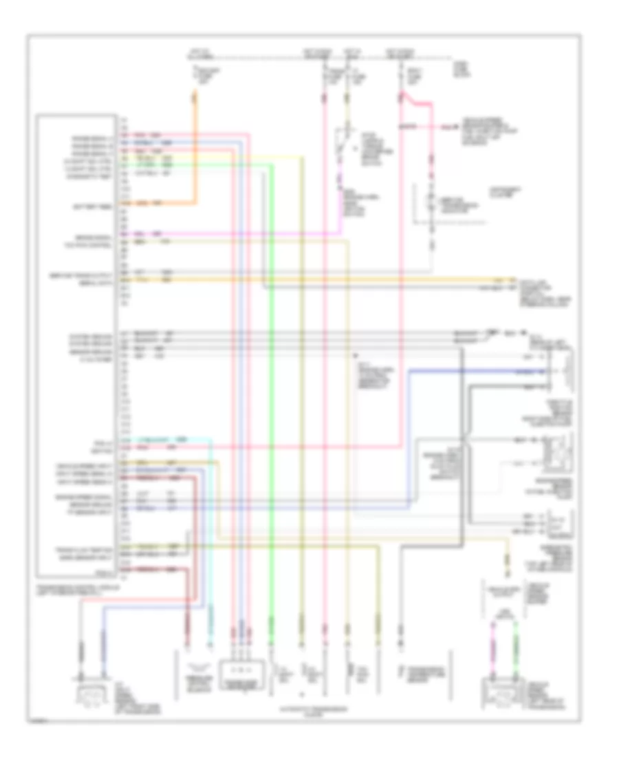
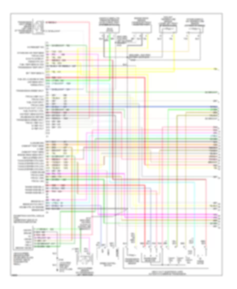
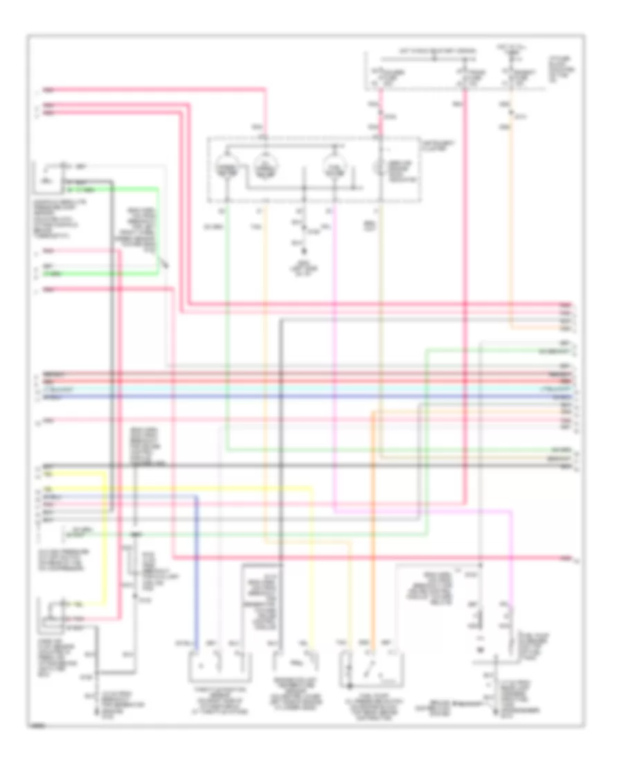
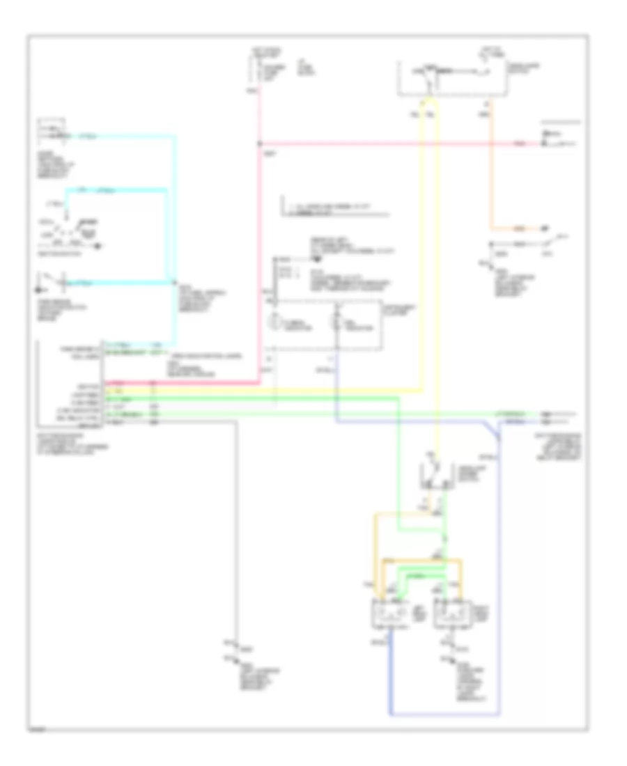
6.5L (VIN Y), Электросхема коробки передач АКПП, 4L80-E для GMC Vandura P1997 3500
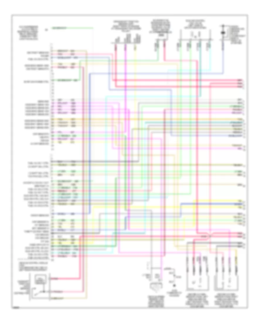
6.5L (VIN Y), Электросхема коробки передач АКПП, 4L80-E для GMC Vandura P1997 3500 - Список элементов:
- 1-2 shift sol
- 1-2 shift sol ctrl
- 2-3 shift sol
- 2-3 shift sol ctrl
- 5 volts ref
- 5v in
- 5v rtn
- A/t input speed sensor (left front side of transmission)
- A10
- A11
- A12
- Automatic transmission (4l80-e)
- B10
- B11
- B12
- Baro sensor input
- Barometric pressure sensor (top left rear of intake manifold)
- Battery feed
- Brake signal
- C10
- C11
- C12
- C13
- C14
- C15
- C16
- D10
- D11
- D12
- D13
- D14
- D15
- D16
- Dash fuse block
- Data link connector (partial) (below dash, near steering column)
- Diagnostic test
- Ecm bat fuse 20a
- Ecm-1 fuse 20a
- Engine speed sensor (in fuel injection pump)
- Engine speed signal
- G114 (rear of left cylinder head)
- Hot at all times
- Hot in run
- Hot in run or start
- I-3 fuse 15a
- Ignition
- Input speed sens hi
- Input speed sens lo
- Instrument cluster
- Out
- Pcs hi
- Pcs lo
- Pnk
- Pnk n
- Pressure control solenoid
- Range mode selector
- Range signal a
- Range signal b
- Range signal c
- Red
- Red p
- S108
- S111 (engine harn, 10 cm from generator breakout)
- S119 (engine harn, 6 cm from glow plug switch breakout)
- S143
- S200 (engine harn, near ignition switch)
- Sensor ground
- Serial data
- Service trans output
- Service transmission indicator
- Stop lamps & torque converter brake switch
- System ground
- Tan
- Tcc pwm control
- Tcc pwm sol
- Throttle position sensor (right side of fuel injection pump)
- Tp sensor input
- Trans fluid temp sig
- Trans fuse 10a
- Transmission control module (left interior firewall)
- Transmission temperature sensor
- Vehicle spd output
- Vehicle speed input
- Vehicle speed sensor (left rear of transmission)
- Vehicle speed sensor buffer
- Vehicle speed sensor buffer & fuel injection pump fuel shut off solenoid
- Vss inputs
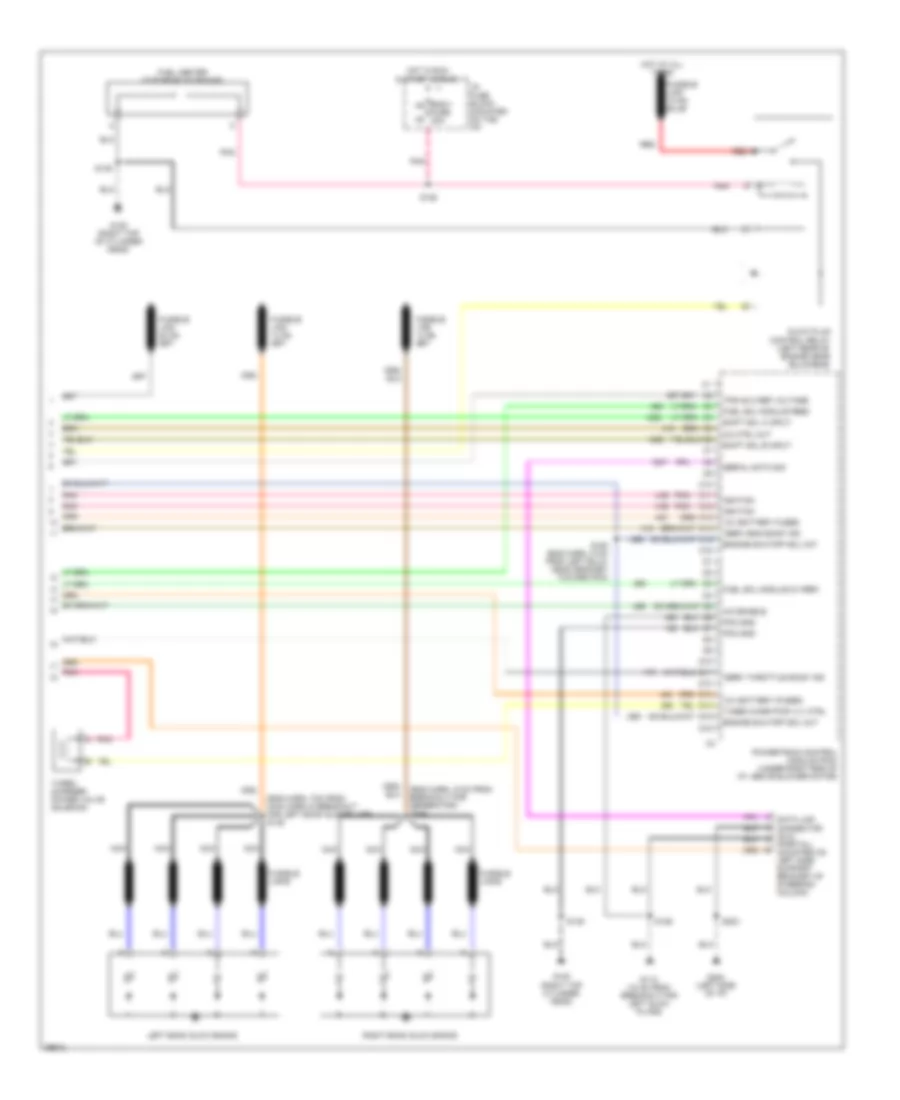
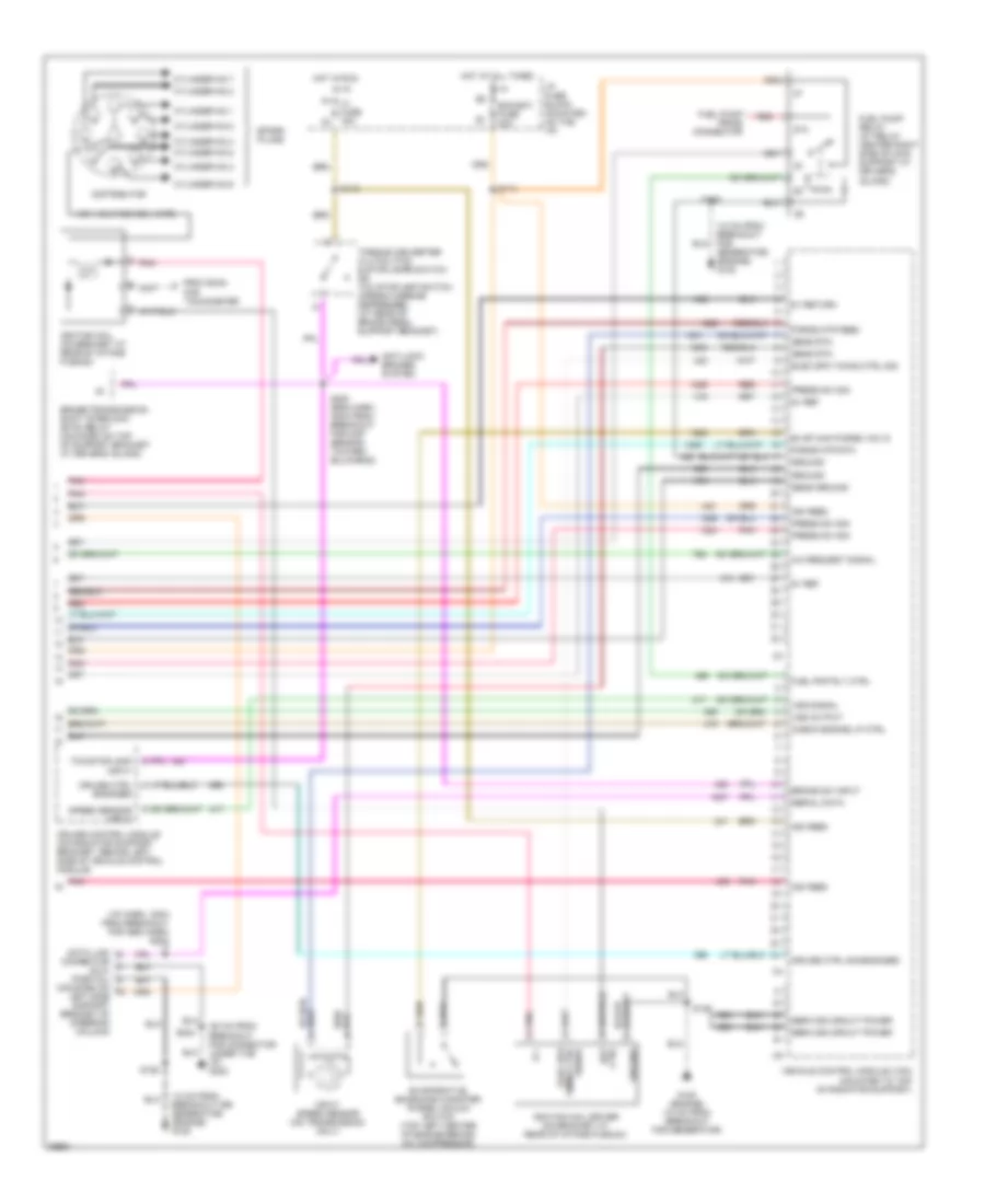
7.4L
7.4L (VIN J), Электросхема коробки передач АКПП, 4L80-E для GMC Vandura P1997 3500
7.4L (VIN J), Электросхема коробки передач АКПП, 4L80-E для GMC Vandura P1997 3500 - Список элементов:
- (a/t output speed sensor)
- (mil)
- (twisted wire pair)
- 1-2 shift
- 1-2 shift sol
- 2-3 shift sol
- 2-3 shift solenoid
- 5v reference
- A/c compressor relay, generator & seat belt/ headlamp alarm module
- A/t input speed sensor (left side of transmission)
- A/t iss hi in
- A/t iss lo in
- Automatic transmission (4l80-e)
- Battery in
- Brake switch input
- Buss bar
- Cooling fans & engine controls systems
- Cruise control module & switch
- Dash fuse block
- Data class ii
- Data link connector (partial) (below dash, near steering column)
- Ecm bat fuse 20a
- Ecm-1 fuse 20a
- Ect sens input
- Eng-1 fuse 20a
- Engine coolant temperture sensor (top front of engine)
- Fuel injectors (engine controls system)
- Fuel pump relay & switch
- G120 (10 cm from breakout for generator)
- Gauges fuse 20a
- Hot at all times
- Hot in run
- Hot in run or start
- I-3 fuse 15a
- Ignition in
- Instrument cluster
- Mil control
- Pcm ground
- Pcs sol hi out
- Pcs sol lo out
- Pnk
- Press ctrl
- Range signal "a"
- Range signal "b"
- Range signal "c"
- Red
- S114
- S116
- S119 (engine harness, 4 cm from breakout to generator)
- S121
- S126
- S128
- S154
- S200 (eng harn, 45 cm from breakout to map sensor)
- Sensor ground
- Sensor return
- Service engine soon indicator
- Solenoid
- Stop lamps & torque converter clutch switch
- Tcc pwm
- Tcc pwm sol
- Throttle position sensor (on throttle body)
- Tp sens input
- Trans fluid temp sensor
- Trans fuse 10a
- Trans range pressure switch assembly
- Trans temp sig in
- Vehicle control module (center front of engine compt)
- Vehicle speed sensor (left rear of transmission)
- Vss hi
- Vss lo
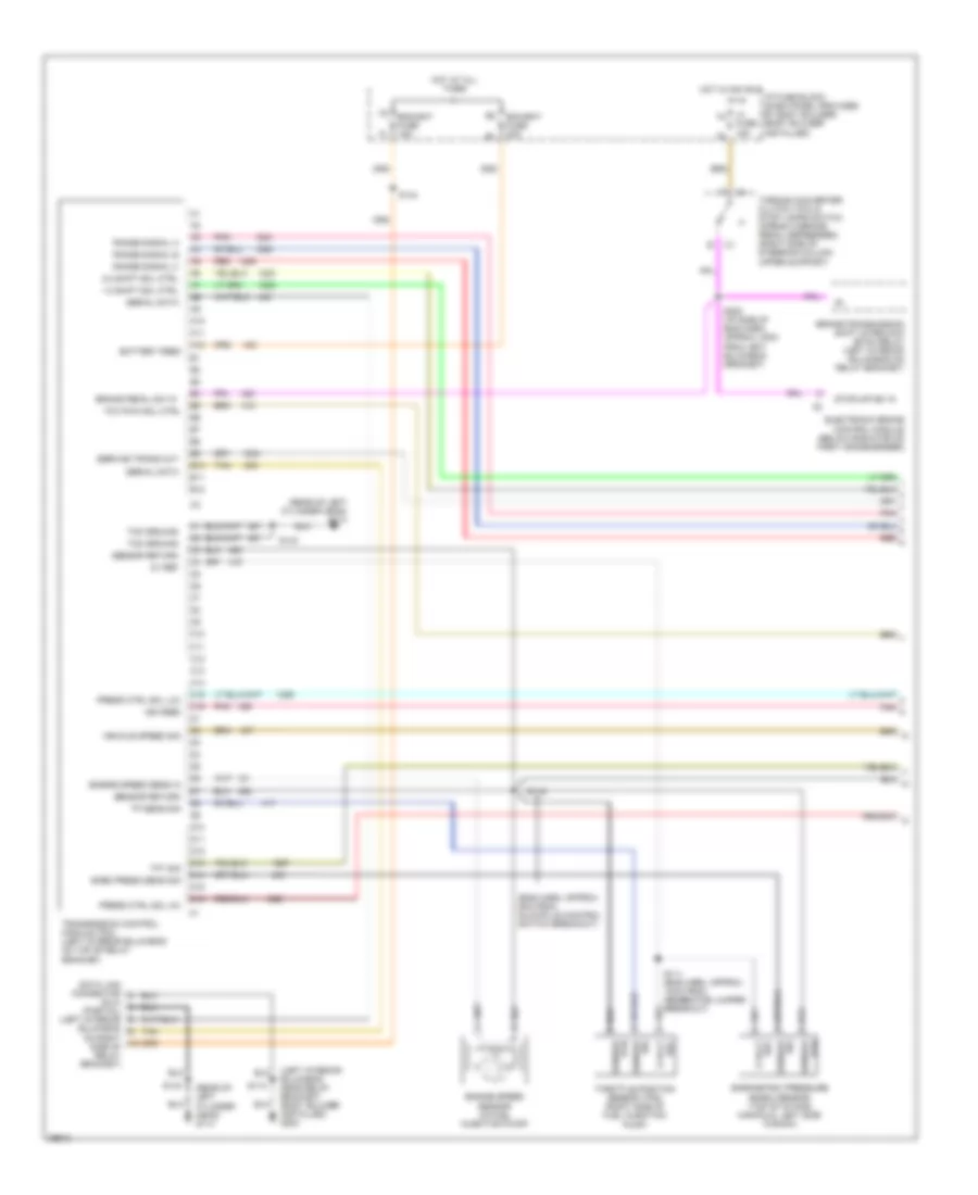
7.4L (VIN N), Электросхема коробки передач АКПП, 4L80-E для GMC Vandura P1997 3500
7.4L (VIN N), Электросхема коробки передач АКПП, 4L80-E для GMC Vandura P1997 3500 - Список элементов:
- (engine harn, 4 cm from generator breakout)
- (engine harness, 4 cm from coolant fan motor breakout)
- (engine) (18 cm from breakout for chassis harness)
- (mil)
- 1-2 shift sol
- 1-2 shift sol ctrl
- 2-3 shift sol
- 2-3 shift sol ctrl
- 5v reference
- A/c compressor, drl module, drl relay, generator, instrument cluster & seat belt/headlamp alarm module
- A/t input speed sensor (left side of transmission)
- A1 a1
- A14
- A15
- All times
- Anti-lock brakes & cruise control systems
- Automatic transmission (4l80-e)
- Battery feed
- Brake sig
- Buss bar
- Dash fuse block
- Data link connector (partial) (below dash, near steering column)
- Diagnostic test
- E11
- E13
- E15
- E16
- Ecm bat fuse 20a
- Ecm-i fuse 20a
- Ect sig
- Engine controls systems
- Engine coolant temperature sensor (top front of engine)
- F10
- F12
- F13
- F14
- F15
- Fuel injectors (engine controls)
- Fuel pump relay & switch
- Gauges fuse 20a
- Hot at
- Hot in run
- Hot in run or start
- Hot in run, bulb
- I-3 fuse 15a
- Ignition feed
- Instrument cluster
- Mil control
- Or start
- Pcm ground
- Pnk
- Powertrain control module (left side of dash)
- Pressure control hi
- Pressure control lo
- Pressure control sol
- Range mode selector
- Range signal "a"
- Range signal "b"
- Range signal "c"
- Red
- S114
- S116
- S118
- S119
- S121
- S126
- S154
- S200 (i/p harness, under instrument cluster)
- Sensor ground
- Serial data
- Service engine soon indicator
- Stop lamps & torque converter brake switch
- Tan
- Tcc
- Tcc pwm sol
- Test or start
- Throttle position sensor (on side of throttle body)
- Tp signal
- Trans fluid temp sensor
- Trans fluid temp sig
- Trans fuse 10a
- Trans input speed
- Vehicle speed sensor (left rear side of transmission)
- Vehicle speed sensor buffer (above accelerator pedal)
- Vss signal hi in
- Vss signal lo in
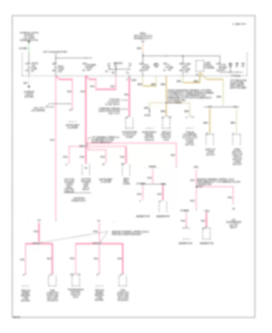
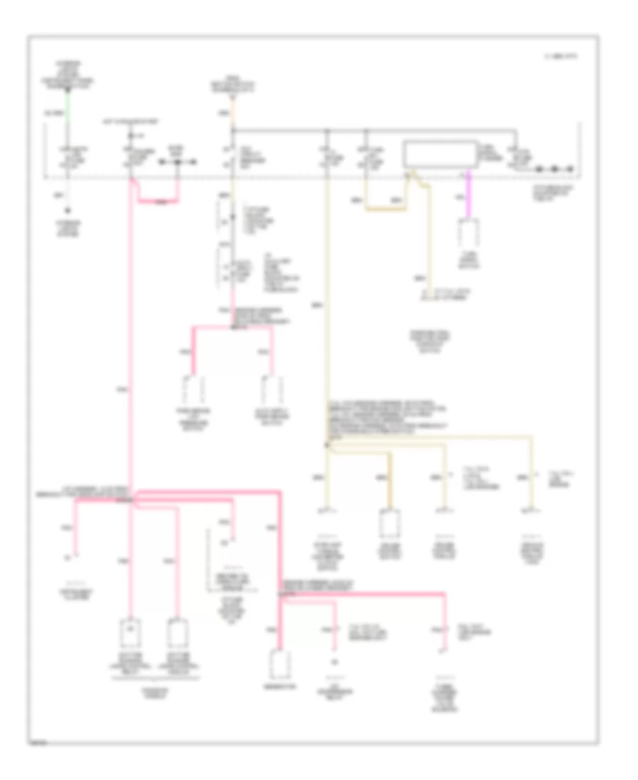
БЛОК ПРЕДОХРАНИТЕЛЕЙ И РЕЛЕ
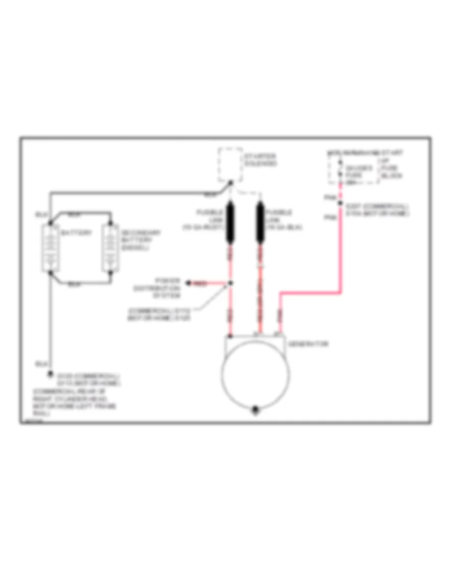
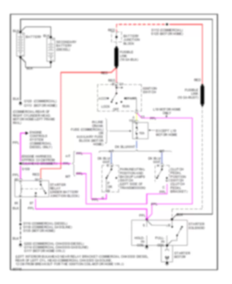
Электросхема блока предохранителей и реле, коммерческое шасси (1 из 4) для GMC Vandura P1997 3500
Электросхема блока предохранителей и реле, коммерческое шасси (1 из 4) для GMC Vandura P1997 3500 - Список элементов:
- (105a)
- (diesel a/t-engine harness, approx 19 cm from a/c compresssor clutch relay, others-engine harness, approx 11 cm from steering column connector breakout) s144
- (i/p harness, approx 20 cm from fuse block breakout) s204
- (others)
- A/c compressor clutch relay
- A12
- Accessory junction block (left interior bulkhead, near relay bracket)
- Auxiliary engine coolant fan relay (diesel only)
- B b8
- B c8
- B stud
- Batt bus
- Battery
- Battery junction block (left side of engine bulkhead, above relay bracket)
- Data link connector (dlc)
- Diesel
- Dome lamp (provisions for)
- E2 ecm- bat fuse 20a
- Eng- bat fuse 15a
- F7 tail lps fuse 20a
- Fuel pump relay
- Fuel pump switch & engine oil pressure gauge sensor
- Fusible link 10 ga. rust
- Fusible link 18 ga. rust
- G7 stop- haz fuse 15a
- Gas
- Generator
- Glow plug control switch (diesel only)
- Hazard warning lamps flasher
- Headlamps switch
- Horn relay
- Horn/ dm fuse 20a
- I/p fuse block (dash panel provided by body builder)
- P b2
- P c2
- Pwr bus
- Pwr fuse 30a
- Red
- Red (diesel-engine harness, 4-16 cm from starter motor breakout, gasoline-engine harness, 7 cm from generator jumper breakout) s112
- Remote battery access terminal block (rear of right radiator core support panel)
- S134
- S206 (i/p harness, approx 12 cm before i/p fuse block breakout)
- Seat belt/ lamps alarm
- Secondary battery (diesel only)
- Starter relay
- Starter solenoid (at starter, lower right side of engine)
- Stud
- To ignition switch (diagram 2 of 4)
- Torque converter clutch & stoplamps switch
- Transmission control module (a/t only)
- Vehicle control module (vcm)
- W/deluxe school bus (b3m) only
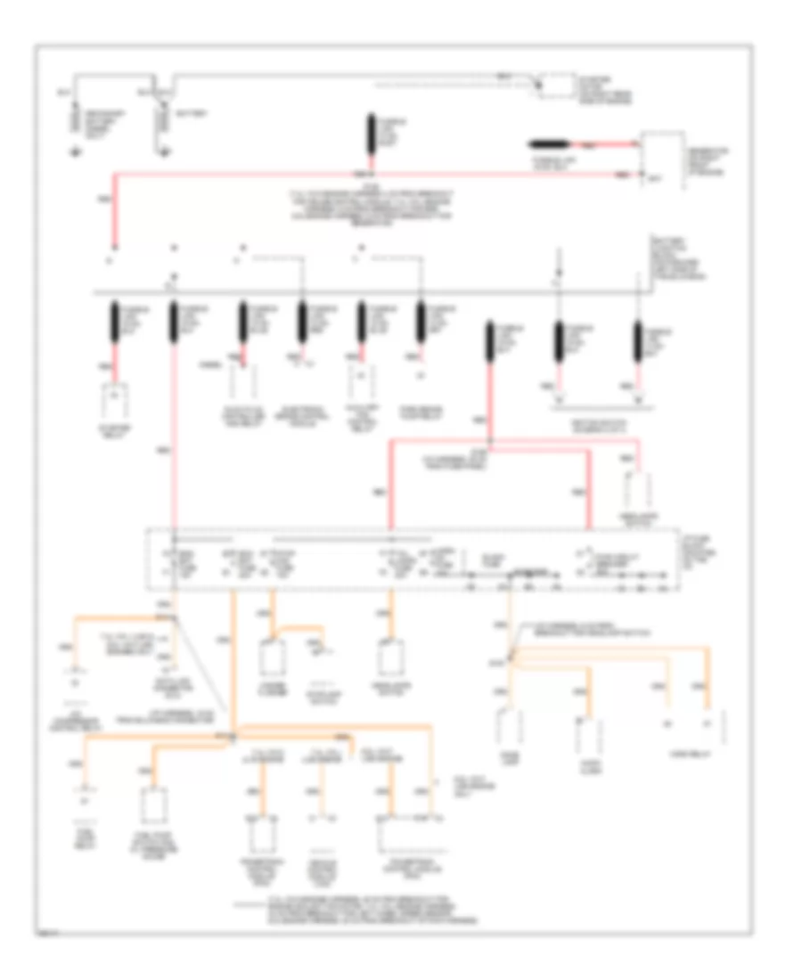
Электросхема блока предохранителей и реле, коммерческое шасси (2 из 4) для GMC Vandura P1997 3500
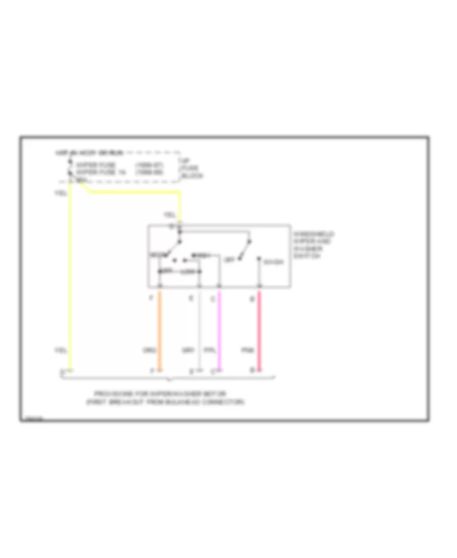
Электросхема блока предохранителей и реле, коммерческое шасси (2 из 4) для GMC Vandura P1997 3500 - Список элементов:
- (engine harness, approx 18 cm from right engine breakout)
- (engine harness, approx 5 cm from right glowplug breakout) s116
- (engine harness, approx 6 cm before mass air flow sensor breakout) s116
- (i/p harness, approx 15 cm after i/p fuse block breakout) s211
- 10a
- A a6
- A b6
- A c6
- A/t
- Acc
- Acc bus
- Acc e5
- Automatic transmission (at)
- Auxiliary engine coolant fan relay
- Camshaft position (cmp) sensor
- Clutch pedal position (cpp) switch
- Crank fuse (engine harness, in-line fuse block near right side of steering column upper support)
- Crk (start)
- Diesel
- Eng-1 fuse 20a
- Evaporative emissions (evap) canister purge solenoid valve
- Exhaust gas recirculation (egr) valve
- Fuel heater
- Fuel injection pump cold advance solenoid engine coolant temperature (ect) switch
- Gas
- Gauges fuse, ecm-1 fuse: (4.3l vin w (l35) engine) (5.7l vin r (l31) engine) (6.5l vin y (l57) engine)
- Glow plug control switch
- Heated oxygen sensor (ho2s) left pre- converter
- Heated oxygen sensor (ho2s) post converter (4.3l vin w (l35) engine) heated oxygen sensor (ho2s) left post converter (5.7l vin r (l31) engine)
- Heated oxygen sensor (ho2s) right post converter (5.7l vin r (l31) engine)
- Heated oxygen sensor (ho2s) right pre- converter
- I/p fuse block (dash panel provided by body builder)
- Ignition switch
- Lock
- M/t
- Mass air flow (maf) sensor
- Nca
- Off
- On (run)
- Park/neutral position (pnp) & backup lamps switch
- Pnk
- Provisions windshield washer motor
- Radio fuse 10a
- Red
- S139
- To i/p fuse block: (diagram 4 of 4)
- Trans fuse 10a
- Vehicle control module (vcm)
- Water- in-fuel indicator sensor
- Windshield wiper & washer switch
- Wiper fuse 25a
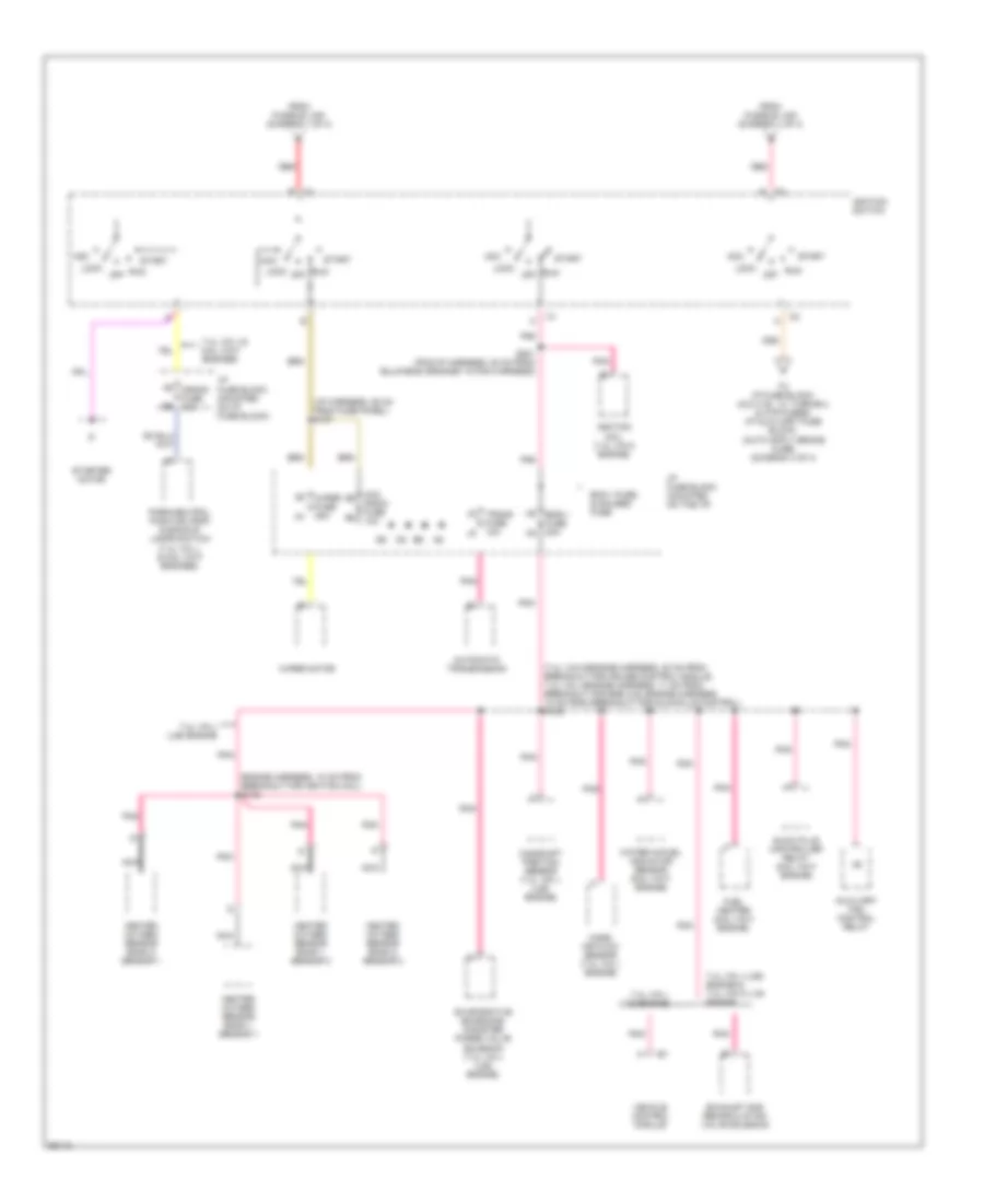
Электросхема блока предохранителей и реле, коммерческое шасси (3 из 4) для GMC Vandura P1997 3500
Электросхема блока предохранителей и реле, коммерческое шасси (3 из 4) для GMC Vandura P1997 3500 - Список элементов:
- (engine harness, approx 10 cm from breakout to right side of engine crossover harness) s108
- (engine harness, approx 9 cm from right h2os breakout) s108
- 4.3l vin w (l35) engine
- 5.7l vin r (l31) engine
- Crankshaft position (ckp) sensor
- Crankshaft position sensor (ckp)
- Ecm-1 fuse 20a
- Electronic ignition (ei) coil driver module
- Fuel injector no.1
- Fuel injector no.2
- Fuel injector no.3
- Fuel injector no.4
- Fuel injector no.5
- Fuel injector no.6
- Fuel injector no.7
- Fuel injector no.8
- Hot in run or start
- I/p fuse block (dash panel provided by body builder)
- Ignition coil
- Instrument cluster
- Pnk
- Vehicle control module (vcm)
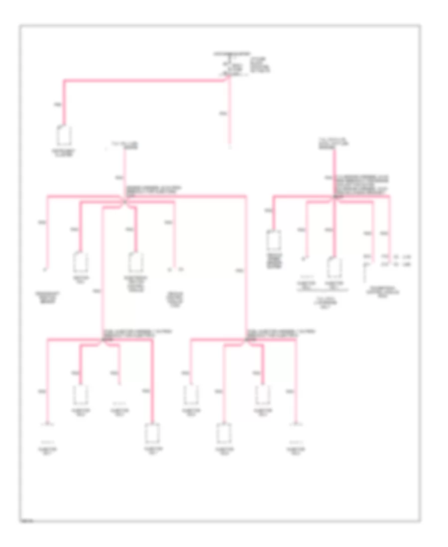
Электросхема блока предохранителей и реле, коммерческое шасси (4 из 4) для GMC Vandura P1997 3500
Электросхема блока предохранителей и реле, коммерческое шасси (4 из 4) для GMC Vandura P1997 3500 - Список элементов:
- (engine harness, approx 19 cm pnk
- (engine harness, approx 26 cm from bulkhead grommet)
- (gasoline-engine harness, 8 cm from vcm breakout, diesel-engine harness, 13 cm from a/c compressor high pressure cut-off switch breakout) s133 (gasoline) s124 (diesel)
- (i/p harness, approx 40 cm before i/p fuse block breakout)
- 105a
- 1996 vftc c
- 6.5l vin y (l57) engine
- A/c compressor clutch relay
- A/t
- Back up lamps switch
- C16
- C208
- Canadian models only
- D4 htr fuse 25a d3
- Daytime running lamp (drl) relay
- Daytime running lamps (drl) control module
- Diesel
- E4 turn- b/u fuse e3 15a
- Ecm-1 fuse 20a
- Electronic brake control module
- F4 i-3 fuse 15a f3
- F6 gauges fuse 20a f5
- From breakout to steering column connector) s132
- From ignition switch (diagram 2 of 4)
- Fuel injection pump fuel shut-off solenoid
- G4 aux fuse 30a g3
- Gas
- Generator
- Hot in run or start
- Htr bus
- I/p fuse block (dash panel provided by body builder)
- Ign bus
- Instr- lps fuse 5a
- Instrument cluster
- Interior lights system
- Interior lights system (i/p lamps dimmer switch)
- M/t
- Nca
- Others
- P/b booster fluid flow alarm
- Park/ neutral position (pnp) & backup lamps switch
- Pnk
- S108
- S207
- Seat belt alarm
- This can plug into c4, b4, or a4
- Torque converter clutch (tcc) & stop lamps switch
- Transmission control module (tcm)
- Turn signal flasher
- Vehicle control module (vcm)
- Vehicle speed sensor (vss) buffer
- W/brake warning indicator system only (uj1)
Электросхема блока предохранителей и реле, шасси кэмпинга (1 из 4) для GMC Vandura P1997 3500
Электросхема блока предохранителей и реле, шасси кэмпинга (1 из 4) для GMC Vandura P1997 3500 - Список элементов:
- (7.4l vin n-engine harness, 45 cm frim breakout for engine coolant fan motor, 7.4l vin j-engine harness, 44 cm from breakout for left wheel speed sensor, 6.5l-engine harness, 20 cm from breakout of main harness)
- (i/p harness, 15 cm from bulkhead connector)
- (i/p harness, 6 cm from breakout for headlamp switch)
- 6.5l vin f (l65) engine
- 6.5l vin f (l65) engine only
- 7.4l vin j (l29) & 6.5l vin f (l65) engines only
- 7.4l vin j (l29) engine
- 7.4l vin n (l19) engine
- A/c compressor control relay
- Audio alarm
- Auxiliary fan control relay
- Bat
- Battery
- Battery junction block (on forward left side of the bulkhead)
- Blank fuse
- Buss bar
- C13
- D13
- Data link connector (dlc)
- Diesel
- Dome lamp
- E16
- E2 ecm- bat fuse 20a
- Electronic brake control module
- Eng- bat fuse 15a
- F7 tail lamps fuse 20a
- Fuel pump relay
- Fuel pump switch and oil pressure gauge
- Fusible link 10 ga. red
- Fusible link 10 ga. rust
- G7 stop- haz fuse 15a
- Generator (on right front of engine)
- Glow plug controller and relay
- Hazard flasher
- Headlamps switch
- Horn relay
- Horn/ dm fuse 20a
- I/p fuse block (mounted on the i/p)
- Ignition switch (diagram 2 of 4)
- Park brake pump relay
- Powertrain control module (pcm)
- Pwr circuit breaker 30a
- Red
- Red a
- S114
- S125 (7.4l vin n-engine harness 4 cm from breakout for cruise control module, 7.4l vin j-engine harness, 5 cm from breakout for egr, 6.5l-engine harness, 9 cm from breakout for generator)
- S141
- S153
- S156 (i/p harness, 35 cm from fuse panel)
- Secondary battery (diesel only)
- Starter motor (on right rear side of engine)
- Starter relay
- Stoplamp switch
- Vehicle control module (vcm)
Электросхема блока предохранителей и реле, шасси кэмпинга (2 из 4) для GMC Vandura P1997 3500
Электросхема блока предохранителей и реле, шасси кэмпинга (2 из 4) для GMC Vandura P1997 3500 - Список элементов:
- (7.4l vin n-engine harness, 30 cm from breakout for cruise control module, 7.4l vin j-engine harness, 11 cm from breakout for egr, 6.5l-engine harness, 12 cm from breakout for glowplug control) s128
- (i/p harness, 25 cm from fuse panel) s157
- 7.4l vin j & 6.5l vin f engines
- 7.4l vin j (l29) engine
- 7.4l vin j (l29) engine & 7.4l vin n (l19) engine
- A6 crank fuse 10a
- Acc
- Acc e5
- Automatic transmission
- Auxiliary fan control relay
- Camshaft position sensor (7.4l vin j (l29) engine)
- Ecm-1 fuse, & gauges fuse
- Eng-1 fuse 20a
- Engine harness, 10 cm from breakout for ignition coil) s133
- Evaporative emissions canister purge valve solenoid (7.4l vin j (l29) engine)
- Exhaust gas recirculation valve solenoid
- From fusible link (diagram 1 of 4)
- Fuel heater (6.5l vin f engine)
- Glow plug controller relay (6.5l vin f engine)
- Heated oxygen sensor bank 1 sensor 1
- Heated oxygen sensor bank 1 sensor 2
- Heated oxygen sensor bank 2 sensor 1
- Heated oxygen sensor bank 2 sensor 2
- I/p fuse block (mounted on i/p fuse block)
- I/p fuse block (mounted on the i/p)
- Ignition coil (7.4l vin n engine)
- Ignition switch
- Lock
- Mass air flow sensor (7.4l vin j engine)
- Nca
- Off
- Park/neutral position (pnp) & backup lamps switch (7.4l vin j, & 6.5l vin f engines)
- Pnk
- Radio fuse 10a
- Red
- Run
- S201 (pcm/i/p harness, 20 cm from bulkhead grommet in pcm harness)
- Start
- Starter motor
- Trans fuse 10a
- Vehicle control module
- Water in-fuel indicator sensor (6.5l vin f engine)
- Wiper fuse 25a
- Wiper motor
Электросхема блока предохранителей и реле, шасси кэмпинга (3 из 4) для GMC Vandura P1997 3500
Электросхема блока предохранителей и реле, шасси кэмпинга (3 из 4) для GMC Vandura P1997 3500 - Список элементов:
- (7.4l-engine harness, 24 cm pnk from breakout for engine coolant fan motor, 6.5l-engine harness, 16 cm from bulkhead grommet) s121
- (engine harness, 28 cm from breakout for injectors) s121
- (fuel injector harness, 7 cm from breakout for injector 5) s158
- (fuel injector harness, 7 cm from breakout for injector 5) s159
- (l19)
- (l65)
- 7.4l vin j (l29) engine
- 7.4l vin n (l19) & 6.5l vin f (l65) engines
- 7.4l vin n (l19) engine only
- C11
- C12
- Crankshaft position sensor
- E15
- Ecm-1 fuse 20a
- Electronic ignition control module
- F15
- Hot in run & start
- I/p fuse block (mounted on the i/p)
- Ignition coil
- Injector no.1
- Injector no.2
- Injector no.3
- Injector no.4
- Injector no.5
- Injector no.6
- Injector no.7
- Injector no.8
- Instrument cluster
- Pnk
- Powertrain control module (pcm)
- Vehicle control module (vcm)
- Vehicle speed sensor buffer
Электросхема блока предохранителей и реле, шасси кэмпинга (4 из 4) для GMC Vandura P1997 3500
Электросхема блока предохранителей и реле, шасси кэмпинга (4 из 4) для GMC Vandura P1997 3500 - Список элементов:
- (7.4l vin n-engine harness, 59 cm from breakout for engine coolant fan motor, 7.4l vin j-engine harness, 52 cm from breakout for map sensor, 6.5l-engine harness, 33 cm from breakout for windshield wiper switch) s116
- (engine harness, 52-58 cm from bulkhead grommet) s115
- (engine harness, pnk
- (i/p harness, 12 cm from breakout for headlamp switch) s154
- 1996 vftc c
- 52-58 cm from bulkhead grommet) s115
- 6.5l vin f (l65) engine only
- 7.4l vin j & 6.5l vin f (l65) engines only
- 7.4l vin j (l29) engine
- 7.4l vin n (l19) & 7.4l vin j (l29) engines
- A c
- A/c compressor relay
- Aux circuit breaker 30a
- Buss bar
- C1 (7.4l vin n) c1 (others)
- Canadian models
- Cruise control module
- Cruise control switch
- D4 htr fuse 25a d3
- Daytime running lamps control module
- Daytime running lamps control relay
- E4 turn b/u fuse e3 15a
- F4 i-3 fuse 15a f3
- F6 gauges fuse 20a f5
- From ignition switch (diagram 2 of 4)
- Generator
- H4 instr- lps fuse 5a
- Hot in run or start
- I/p auxiliary fuse block (mounted on the i/p fuse block)
- I/p fuse block (mounted on the i/p)
- I/p fuse block (mounted on the i/p)
- Instrument cluster
- Interior lights system
- Interior lights system (instrument panel dimmer switch)
- Nca
- Park brake low pressure switch
- Park/neutral position (pnp) & backup switch
- Pnk
- Seatbelts/ lamps alarm module
- Stoplamp torque converter clutch switch
- Turbo charger power valve solenoid
- Turn signal flasher
- Turn signal switch
- Vehicle control module (vcm)
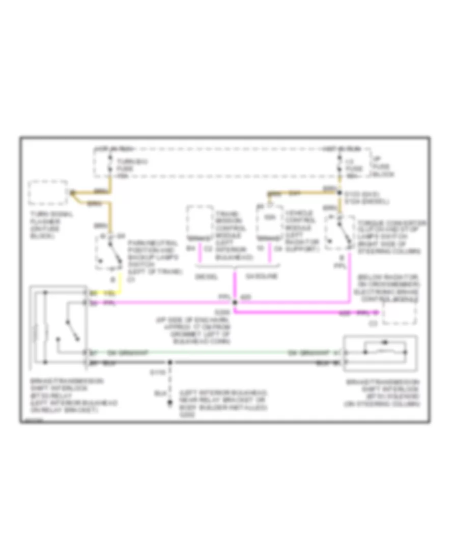
БЛОКИРОВКИ СЕЛЕКТОРА СТОЯНОЧНЫЙ ТОРМОЗ
Электросхема блокировки селектора, коммерческое шасси для GMC Vandura P1997 3500
Электросхема блокировки селектора, коммерческое шасси для GMC Vandura P1997 3500 - Список элементов:
- (below radiator, on crossmember) electronic brake control module
- (left interior bulkhead, near relay bracket or body builder installed) g202
- Brake
- Brake/transmission shift interlock (btsi) relay (left interior bulkhead on relay bracket)
- Brake/transmission shift interlock (btsi) solenoid (on steering column)
- Diesel
- Gasoline
- Hot in run
- I-3 fuse 15a
- I/p fuse block
- Ign
- Park/neutral position and backup lamps switch (left of trans)
- S110
- S133 (gas) s124 (diesel)
- S200 (i/p side of eng harn, approx 17 cm from grommet left of bulkhead conn)
- Torque converter clutch and stop lamps switch (right side of steering column)
- Trans- mission control module (left interior bulkhead)
- Turn b/u fuse 15a
- Turn signal flasher (on fuse block)
- Vehicle control module (left radiator support)
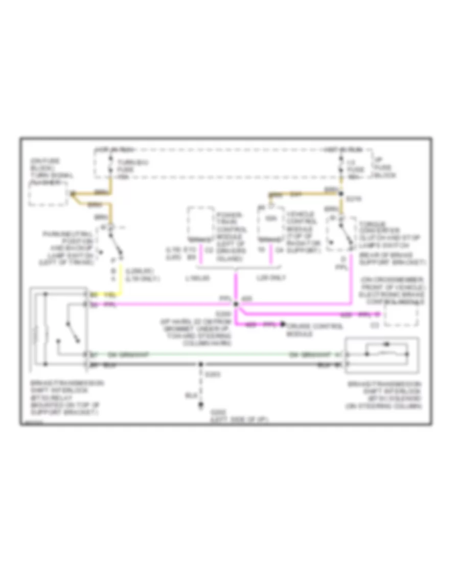
Электросхема блокировки селектора, шасси кэмпинга для GMC Vandura P1997 3500
Электросхема блокировки селектора, шасси кэмпинга для GMC Vandura P1997 3500 - Список элементов:
- (l19) (l65)
- (l29/l65) (l19 only)
- (on crossmember, front of vehicle) electronic brake control module
- (on fuse block) turn signal flasher
- (rear of brake support bracket)
- B a
- Brake
- Brake/transmission shift interlock (btsi) relay (mounted on top of support bracket)
- Brake/transmission shift interlock (btsi) solenoid (on steering column)
- Cruise control module
- E13 b9
- G202 (left side of i/p)
- Hot in run
- I-3 fuse 15a
- I/p fuse block
- Ign
- L19/l65
- L29 only
- Park/neutral position and backup lamp switch (left of trans)
- Power- train control module (left of driver's island)
- S200 (i/p harn, 22 cm from grommet under i/p, toward steering column harn)
- S203
- S216
- Torque converter clutch and stop lamps switch
- Turn b/u fuse 15a
- Vehicle control module (top of radiator support)
ВНЕШНЕЕ ОСВЕЩЕНИЕ
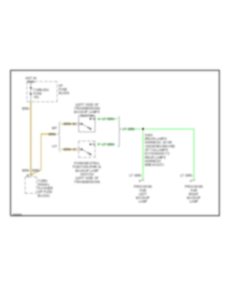
Электросхема заднего хода, коммерческое шасси для GMC Vandura P1997 3500
Электросхема заднего хода, коммерческое шасси для GMC Vandura P1997 3500 - Список элементов:
- (left side of transmission) backup lamps switch
- A/t
- Hot in run
- I/p fuse block
- M/t
- Park/neutral position (pnp) & backup lamp switch (left side of transmission)
- Provision for left backup lamp
- Provision for right backup lamp
- S403 (rear lamps harness, 65 or 120cm rearward of taillamps extension to rear lamps harness breakout)
- Turn b/u fuse 15a
- Turn signal flasher (i/p fuse block)
Электросхема заднего хода, шасси кэмпинга для GMC Vandura P1997 3500
Электросхема заднего хода, шасси кэмпинга для GMC Vandura P1997 3500 - Список элементов:
- (left side of transmission) backup lamp switch
- 7.4l vin n (l19) engine
- All except 7.4l vin n (l19) engine
- Hot in run
- I/p fuse block
- Park/neutral position (pnp) & backup lamp switch (left side of transmission)
- Provision for backup lamps (on left frame rail near rear lamp harness)
- Provision for rear mounted camera (near breakout for steering column harness)
- S134 (engine harn, near breakout for starter motor)
- Turn b/u fuse 15a
- Turn signal flasher (i/p fuse block)
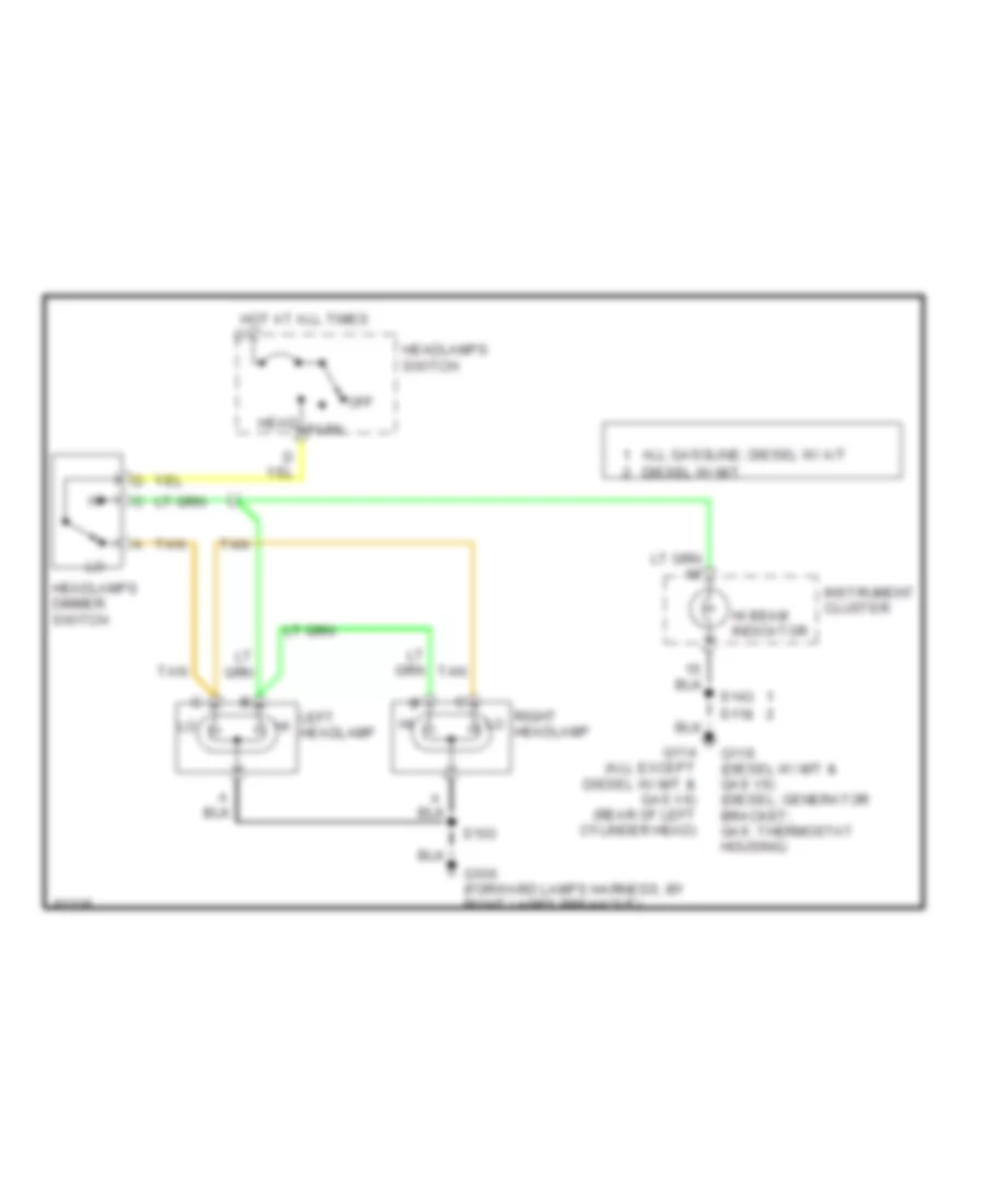
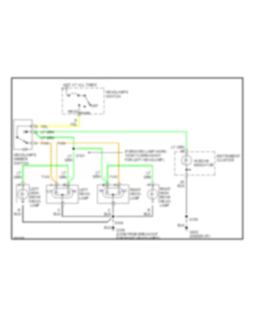
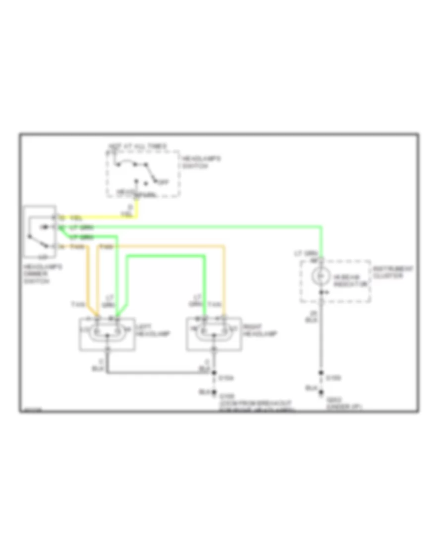
Электросхема внешнего освещения, коммерческое шасси для GMC Vandura P1997 3500
Электросхема внешнего освещения, коммерческое шасси для GMC Vandura P1997 3500 - Список элементов:
- (forward lamps harn, 4cm from horn conn breakout) s101
- (i/p harness headlamp switch breakout, 8cm before i/p fuse block breakout) s208
- (rear lamps harness, 55 or 110cm from tail/ stoplamps extension harness to rear lamps harness, near left frame rail and fuel tank) s402
- Backup lamps circuit
- C205 (near i/p fuse block)
- G114 (all except diesel w/ m/t & gas v6 engine) (rear of left cylinder head)
- G119 (diesel w/ m/t & gas v6 engine) (diesel: generator bracket; gas: thermostat housing)
- Hazard
- Hazard lamps flasher (left inner bulkhead on relay bracket)
- Head
- Headlamps switch
- Hot at all times
- Hot in run
- I/p fuse block
- Instrument cluster
- Interior lamps system
- Left front park & turn signal (t/s) lamp
- Left front side marker lamp
- Left rear license lamps
- Left turn ind.
- Normal
- Off
- Park
- Provision for center high mounted stop lamp
- Provisions for left rear side marker lamp
- Provisions for left tail/stop & turn signal lamps
- Provisions for marker lamps
- Provisions for right rear side marker lamp
- Provisions for right tail/stop & turn signal lamps
- Right front park & turn signal (t/s) lamp
- Right front side marker lamp
- Right rear license lamps
- Right turn ind.
- S101 (forward lamps harn, 4cm from horn conn breakout)
- S104 (forward lamps harn, 15cm after right lamps breakout)
- S105 (forward lamps harn, 10cm before right lamps breakout)
- S143
- S404 (rear lamps harness, 5cm from right tail- lamps breakout)
- S405 (rear lamps harness, 5cm from left taillamps breakout)
- Stop
- Stop haz fuse 15a
- Tail
- Tail lamps fuse 20a
- Torque converter clutch & stop lamps switch (right side of steering column upper support)
- Turn
- Turn b/u fuse 15a
- Turn left
- Turn right
- Turn signal flasher
- Turn signal switch
Электросхема внешнего освещения, шасси кэмпинга для GMC Vandura P1997 3500
Электросхема внешнего освещения, шасси кэмпинга для GMC Vandura P1997 3500 - Список элементов:
- (forward lamp harn, 5cm from left head- lamp breakout) s102
- (forward lamp harn, 5cm from right headlamp breakout) s106
- Backup lamps circuit
- Cruise control system
- G112 (6.5l vin f (l65) engine) (near breakout for left glow plugs)
- G120 (7.4l vin j (l29) engine) (near breakout for generator)
- Hazard
- Hazard lamps flasher (inner left side of main support bracket)
- Head
- Headlamps switch
- Hot at all times
- Hot in run
- I/p fuse block
- Instrument cluster
- Interior lamps system
- Left front park & turn signal (t/s) lamp
- Left turn indic
- No ground available (7.4l vin n (l19) engine) (near breakout for chassis harness)
- Normal
- Off
- Park
- Provision for center high mounted stop lamp
- Provisions for left front side marker lamp
- Provisions for left rear license lamp
- Provisions for left rear side marker lamp
- Provisions for left tail, stop & turn signal (t/s) lamps
- Provisions for marker lamps
- Provisions for right front side marker lamp
- Provisions for right rear license lamp
- Provisions for right rear side marker lamp
- Provisions for right tail, stop & turn signal (t/s) lamps
- Right front park & turn signal (t/s) lamp
- Right turn indic
- S105 (forward lamp harn, 9cm from right headlamp breakout)
- S117 (l19 engine) (engine harness, 43cm from engine cooling fan notor harn breakout) (l29/l65 engine) (engine harness, 7cm from windshield wiper motor breakout)
- S124 (engine harness, near cruise control harness breakout)
- S126
- S152 (i/p harness, 25cm from headlamp switch connector)
- S402 (rear lamp harness, rear of vehicle)
- S404 (rear lamp harness, rear of vehicle)
- S405 (rear lamp harness, rear of vehicle)
- Stop haz fuse 15a
- Tail lamps fuse 20a
- Torque converter clutch & stop lamps switch (brake pedal support bracket)
- Turn
- Turn b/u fuse 15a
- Turn left
- Turn right
- Turn signal flasher
- Turn signal switch
ВНУТРЕННЕЕ ОСВЕЩЕНИЕ
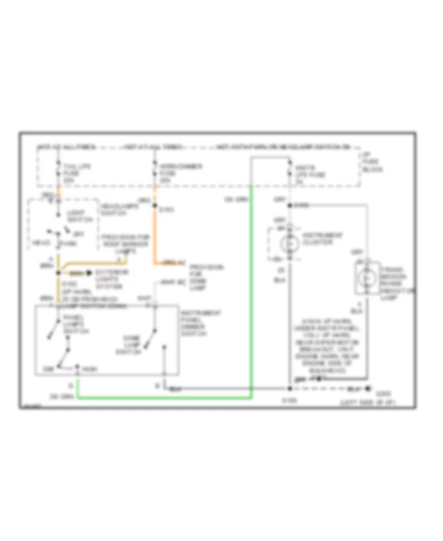
Электросхема освещения салона, коммерческое шасси для GMC Vandura P1997 3500
Электросхема освещения салона, коммерческое шасси для GMC Vandura P1997 3500 - Список элементов:
- (5)
- (steering column on lower mounting stud of headlamps dimmer switch)
- Breakout)
- C207
- Dash lamps input
- Dim
- Dome lamp switch
- Exterior lights system
- G119 (diesel m/t) g114 (others)
- G207
- Head
- Headlamps switch
- High
- Horn dim fuse 20a
- Hot at all times
- I/p fuse block
- I/p lamps dimmer switch
- Instr lps fuse 5a
- Instrument cluster
- Light switch
- Off
- Panel lamps switch
- Park
- Prndl lamp
- Provision for dome lamp (i/p harn, first breakout from interior bulkhead)
- Provision for marker lamps
- S118 (diesel m/t) s143 (others)
- S204
- S205
- Seat belt alarm (i/p fuse block)
- Steering column
- Tail lps fuse 20a
Электросхема освещения салона, шасси кэмпинга для GMC Vandura P1997 3500
Электросхема освещения салона, шасси кэмпинга для GMC Vandura P1997 3500 - Список элементов:
- (6)
- (i/p harn, 25 cm from head- lamp switch conn)
- (left side of i/p)
- (vin n: i/p harn, under instr panel; vin j: i/p harn, near wiper motor breakout; vin f: engine harn, near engine side of bulkhead)
- Dim
- Dome lamp switch
- Exterior lights system
- G202
- Head
- Headlamps switch
- High
- Horn dimmer fuse 20a
- Hot at all times
- Hot with park or headlamp switch on
- I/p fuse block
- Instr lps fuse 5a
- Instrument cluster
- Instrument panel dimmer switch
- Lamp
- Light switch
- Off
- Panel lamps switch
- Park
- Provision for dome b
- Provision for roof marker lamps
- S150
- S152
- S153
- S155
- S203
- Tail lps fuse 20a
- Trans- mission range indicator lamp
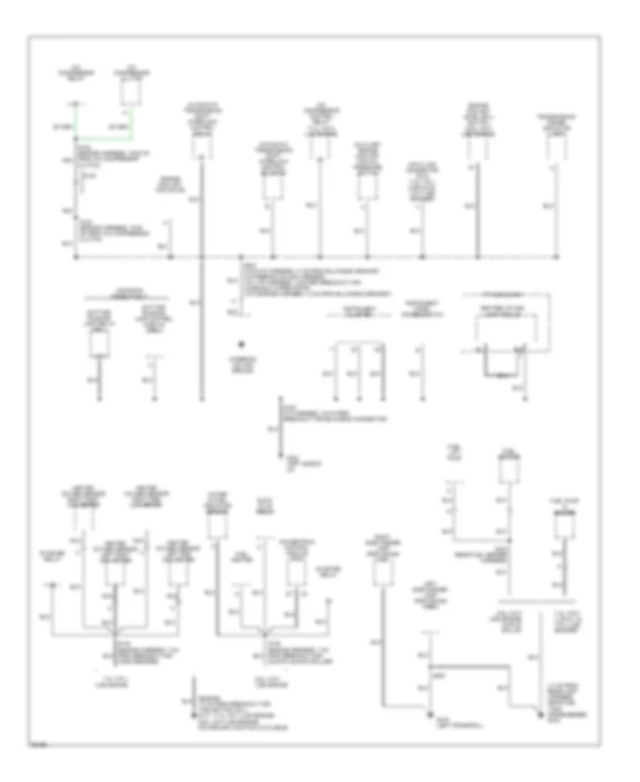
ЗАЗЕМЛЕНИЕ ПОДКЛЮЧЕНИЕ МАССЫ
Электросхема подключение массы заземления, коммерческое шасси (1 из 2) для GMC Vandura P1997 3500
Электросхема подключение массы заземления, коммерческое шасси (1 из 2) для GMC Vandura P1997 3500 - Список элементов:
- (forward lamps harness by left lamps breakout) (body builder installed) g106
- (forward lamps harness by right lamps breakout) (body builder installed) g107
- (left frame rail to rear of left cylinder head) g112
- (left interior bulkhead near relay bracket) (body builder installed) g202
- (rear of left cylinder head) g114
- (rear of right cylinder head to battery) g120
- 87a
- A/c compressor clutch coil
- A/c compressor clutch coil
- A/c compressor clutch coil diode (d101)
- A/c compressor relay
- A/t only
- Automatic transmission only
- Auxiliary engine coolant fan
- Auxiliary engine coolant fan a/c pressure switch
- Battery
- Braided
- Brake/ transmission shift interlock (btsi) relay
- Brake/ transmission shift interlock (btsi) solenoid
- Data link connector (dlc)
- Daytime running lamp (drl) control module
- Daytime running lamp (drl) relay
- Diesel
- Engine
- G114 (rear of left cylinder head to left frame rail)
- G207
- Gasoline
- Gasoline engines
- Heated oxygen sensor (ho2s) left pre- convertor
- Heated oxygen sensor (ho2s) post converter (4.3l vin w (l35) engine) heated oxygen sensor (ho2s) left post converter (5.7l vin r (l31) engine)
- Heated oxygen sensor (ho2s) right post converter (5.7l vin r (l31) engine)
- Heated oxygen sensor (ho2s) right pre- convertor
- Horn hi tone (f-note)
- Horn low tone (a-note)
- I/p lamps dimmer switch
- Instrument cluster
- Left headlamp
- Low engine coolant level indicator sensor
- Nca
- Nca (899)
- Park brake indicator switch
- Prndl lamp
- Right headlamp
- S103 (forword lamps harness, approx 4 cm after (hi tone) horn breakout)
- S110 (engine harness, approx 4 cm from bulkhead connector breakout)
- S110 (engine harness, approx 4 cm from electronic brake control module)
- S118 (engine harness, at left rear of engine, approx 4 cm from ground)
- S124 (engine harness, 13 cm from a/c compressor high pressure cut- off switch breakout)
- S124 (engine harness, approx 13 cm from a/c compressor high pressure cut-off switch breakout)
- S205 (i/p harness, approx 4 cm before i/p fuse block breakout)
- Seat belt/ lamps alarm
- Secondary battery
- Starter relay
- Steering column
- Steering column on lower mounting stud of headlamps dimmer switch
- W/6.5l vin y (l57) diesel engine
- W/o daytime running lamps (drl)
Электросхема подключение массы заземления, коммерческое шасси (2 из 2) для GMC Vandura P1997 3500
Электросхема подключение массы заземления, коммерческое шасси (2 из 2) для GMC Vandura P1997 3500 - Список элементов:
- (a/t-engine harness, approx 7 cm from bulkhead grommet, m/t-engine harness, approx 16 cm from a/c compressor switch breakout)
- (engine harness, approx 23-30 cm from breakout to maf sensor)
- (engine harness, approx 7 cm from tps breakout)
- (generator bracket) (rear of left cylinder head)
- (rear of left cylinder head) g114
- (rear of left cylinder head)
- (right rear of rear lamps harness) (body builder installed) g415
- (tail & stop lamps extension harness at crossmember in front of fuel tank) g415
- (thermostat housing) g110
- 5.7l vin r (l31) engine only
- A/c compressor high pressure cutoff switch
- A/t
- Brake pressure differential switch
- Data link connector (dlc)
- Diesel
- Drain wire (shield)
- Electronic brake control module
- Electronic ignition (ei) coil driver module
- Evaporative emissions (evap) canister purge vacuum diagnostic switch
- Fuel heater
- Fuel pump relay
- Fuel sender & fuel pump
- G114
- G119 (m/t) g114 (a/t)
- Gasoline
- Glow plug control switch
- Instrument cluster
- M/t
- Mass air flow (maf) sensor
- Nca
- Nca (450)
- R100 (1100 ohms .75 watts)
- S138
- S140 (a/t-engine harness, approx 4 cm from vss connector)
- S141
- S143
- S143 (engine harness, approx 6 cm from bulkhead connector breakout)
- S161 (electronic brake control module harness, approx 15 cm from right wheel speed sensor breakout)
- Side marker lamp,left rear (provisions for)
- Side marker lamp,right rear (provisions for)
- Transmission control module (tcm)
- Vehicle control module (vcm)
- Vehicle speed sensor (vss) buffer
- Water in-fuel sensor
Электросхема подключение массы заземления, шасси кэмпинга (1 из 2) для GMC Vandura P1997 3500
Электросхема подключение массы заземления, шасси кэмпинга (1 из 2) для GMC Vandura P1997 3500 - Список элементов:
- (10 cm from breakout for generator) (13 cm from breakout for ignition coil)
- (102 cm from breakout harness for the right headlamps) (right frame rail ground) g118
- (18 cm from breakout for chassis harness wires)
- (18 cm from breakout to left glow plugs) (left park lamp ground) g112 (6.5l vin f (l65) engine) (7.4l vin j (l29) & vin n (l19) (engines) (left frame rail ground)
- (23 cm from breakout for the right headlamps) (right park lamp ground) g106
- (7.4l vinj (l29) engine) (6.5l vinf (l65) engine)
- (dual)
- (dual) c
- (engine) (7.4l vin n (l19) engine) (g120) (g112)
- (forward lamp harness, 18 cm to breakout for right headlamp)
- (single)
- (single) a
- 6.5l
- 7.4l
- 7.4l vin j (l29) engine
- A/c compressor high pressure cutoff switch
- A12
- Battery
- Braided strap
- C1 vin f (l65)
- C3 vin j (l29)
- Center high mounted stop lamps (provisions, for)
- Cruise control module
- Cruise control module (7.4l vin n (l19) & 7.4l vin j (l29) engines)
- Data link connector (dlc) (7.4l vin j & 6.5l vin f engines only)
- Daytime running lamps relay 2 (w dual headlamps)
- Drl
- Electronic brake control module
- Electronic ignition control module
- Engine
- Evaporative emissions canister purge vacuum diagnostic switch
- Except drl
- Fuel pump relay
- G113 (left frame rail)
- G118 (right framerail, behind transmission)
- G120 (right frame rail ground)
- Instrument cluster
- Left headlamp
- Left high beam headlamp (w/ dual headlamps)
- Left horn
- Mass air flow sensor (7.4l vin j (l29) engine)
- Nca
- Park brake differential switch
- Park brake motor
- Park brake relay
- Park brake solenoid
- Powertrain control module (pcm) (6.5l vin f (l65) engine)
- Powertrain control module (pcm) (7.4l vin n (l19) engine
- R101 (no resistance or wattage values available)
- Right headlamp
- Right high beam headlamp (w/ dual headlamps)
- Right horn
- S104
- S124 (engine harness, 4-11 cm from breakout for cruise control module)
- S126 (vin j, vin n-engine harness, 5 cm from breakout for cruise control module, vin f-engine harness, 22 cm from breakout for windshield wiper motor)
- S132 (vin j-engine harness, 20 cm from breakout for cruise control module, vin f-engine harness, 35 cm from pcm c1 or c2)
- S138 (engine harness, 7 cm from breakout for maf nca sensor)
- S139 (engine harness, 13 cm from breakout for maf sensor)
- S140 (vin j-engine harness, 20 cm from breakout for cruise control module, vin f-engine harness, 35 cm from pcm c2 or c3)
- Secondary battery (diesel only)
- Stop lamp switch
- Vehicle control module (vcm) (7.4l vin j (l29) engine)
- Vehicle control module (vcm) (7.4l vin j (l29) engine) powertrain control module (pcm) (6.5l vin f (l65) engine)
- Vehicle speed sensor buffer (7.4l vin n (l19) & 6.5l vin f (l65) engines)
- Vss shield
Электросхема подключение массы заземления, шасси кэмпинга (2 из 2) для GMC Vandura P1997 3500
Электросхема подключение массы заземления, шасси кэмпинга (2 из 2) для GMC Vandura P1997 3500 - Список элементов:
- (17 cm from rear/lamp harness, near fuel tank crossmember) g415
- (7.4l vin j (l29) engine)
- (engine) (13 cm from breakout for the ignition coil) g117 (6.5l vin f (l65) engine) (no ground location available)
- 6.5l vin f (l65) engine
- 6.5l vin f (l65) engine (nj9) 80 gallon
- 7.4l vin j (l29) engine
- 7.4l vin n (l19) & 7.4l vin j (l29) engines
- 87a
- A/c compressor clutch
- A/c compressor control relay (7.4l vin n (l19) engine)
- A/c compressor relay
- Automatic transmission shift interlock control relay
- Automatic transmission shift interlock control solenoid
- Auxiliary engine coolant fan a/c pressure switch
- Canadian models only
- Clutch)
- D100
- Data link connector (dlc) (7.4l vin j (l29) & 6.5l vin f (l65) engines)
- Daytime running lamp control module (drl)
- Daytime running lamp relay (drl)
- Engine coolant fan motor
- Engine coolant level (ecl) switch (6.5l vin f (l65) engine)
- Fuel heater
- Fuel lift pump
- Fuel pump & sender
- Fuel sender
- G202 (left side of i/p)
- G416 (left frame rail)
- Glow plug relay
- Glowplug controller)
- Heated oxygen sensor left post converter
- Heated oxygen sensor left pre converter
- Heated oxygen sensor right post converter
- Heated oxygen sensor right pre converter
- Ho2s sensors)
- I/p fuse block
- Instrument cluster
- Instrument panel dimmer switch
- Left side marker lamp (provisions for)
- Nca
- Powertrain control module (pcm)
- Right side marker lamp (provisions for)
- S122 (engine harness, 15-20 cm from a/c compressor nca
- S123 (engine harness, 15-25 cm from a/c compressor clutch)
- S150 (i/p harness, 16 cm from breakout for bulkhead connector)
- S203 (vin n-i/p harness, 41 cm from bulkhead grommet in steering column harness, vin j-i/p harness, 4 cm from breakout for widshield wiper motor, vin f-engine harness, 14 cm from bulkhead grommet)
- S400 (rear fuel sender harness)
- S500
- Seatbelts and lamp module
- Starter relay
- Steering column ground
- Transmission range indicator lamp
- Water in fuel indicator sensor
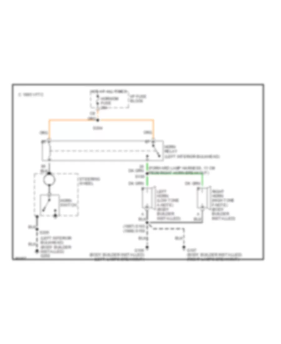
Звуковой сигнал Гудок
Электросхема звукового сигнал Гудка, коммерческое шасси для GMC Vandura P1997 3500
Электросхема звукового сигнал Гудка, коммерческое шасси для GMC Vandura P1997 3500 - Список элементов:
- (1997) s103 (1998) s150
- (forward lamp harness, 11 cm from right horn breakout)
- (left interior bulkhead)
- (left interior bulkhead) (body builder installed) g202
- C 1995 vftc
- G106 (body builder installed) (left lamps breakout)
- G107 (body builder installed) (right lamps breakout)
- Horn relay
- Horn switch
- Horn/dm fuse 20a
- Hot at all times
- I/p fuse block
- Left horn (low tone a-note) (body builder installed)
- Right horn (high tone f-note) (body builder installed)
- S100
- S204
- S205
- Steering wheel
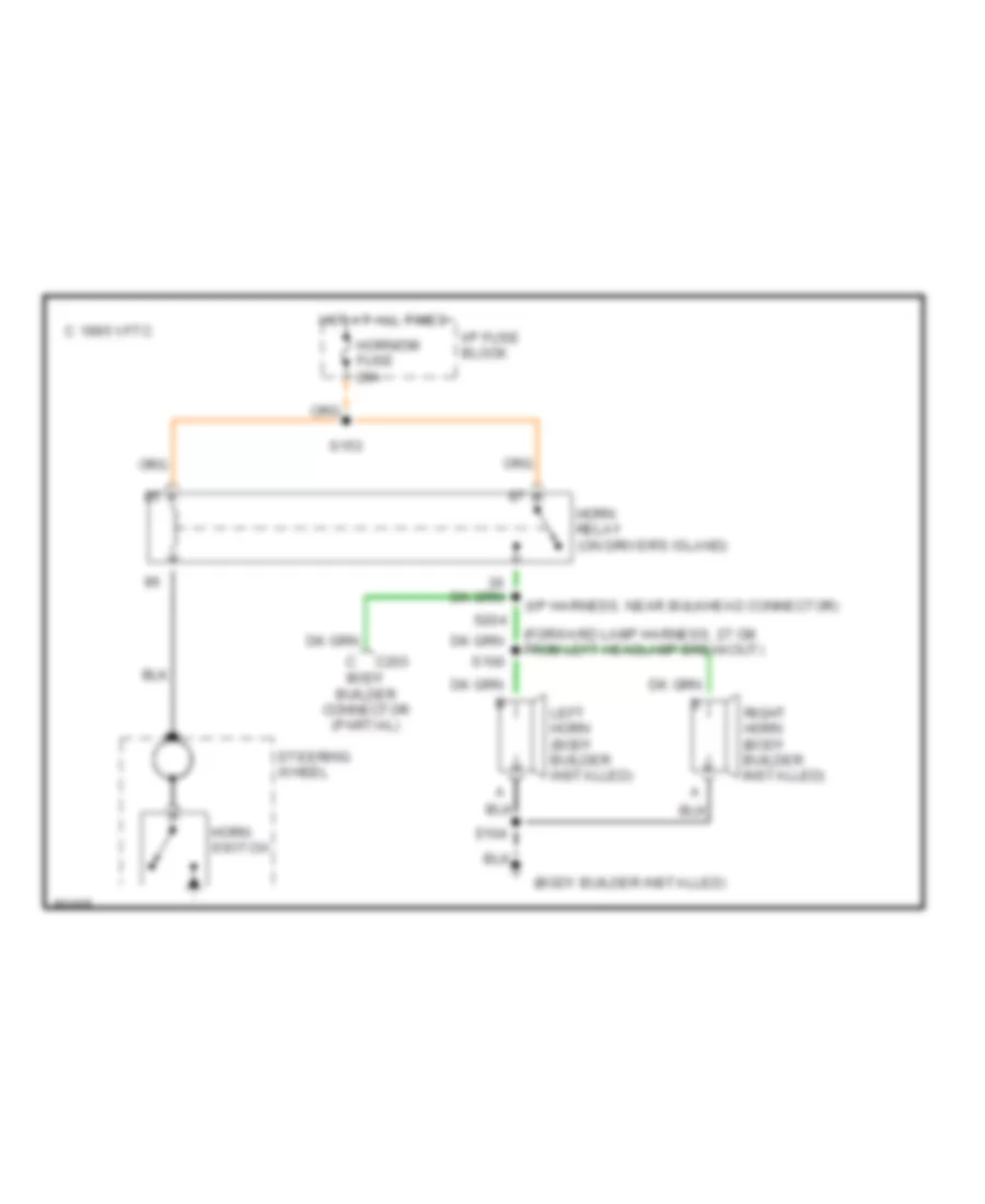
Электросхема звукового сигнал Гудка, шасси кэмпинга для GMC Vandura P1997 3500
Электросхема звукового сигнал Гудка, шасси кэмпинга для GMC Vandura P1997 3500 - Список элементов:
- (body builder installed)
- (forward lamp harness, 27 cm from left headlamp breakout)
- (i/p harness, near bulkhead connector)
- Body builder connector (partial)
- C 1995 vftc
- C203
- Horn relay (on driver's island)
- Horn switch
- Horn/dm fuse 20a
- Hot at all times
- I/p fuse block
- Left horn (body builder installed)
- Right horn (body builder installed)
- S100
- S104
- S153
- S204
- Steering wheel
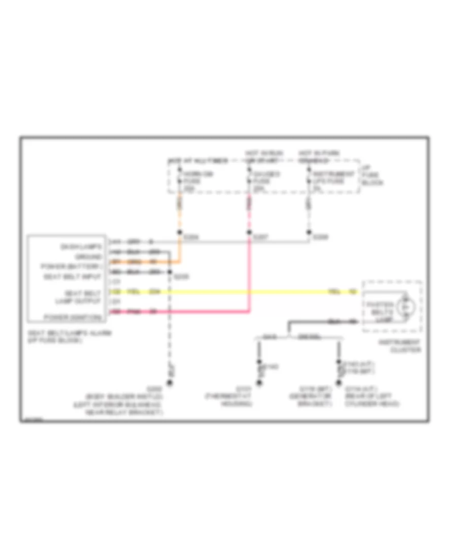
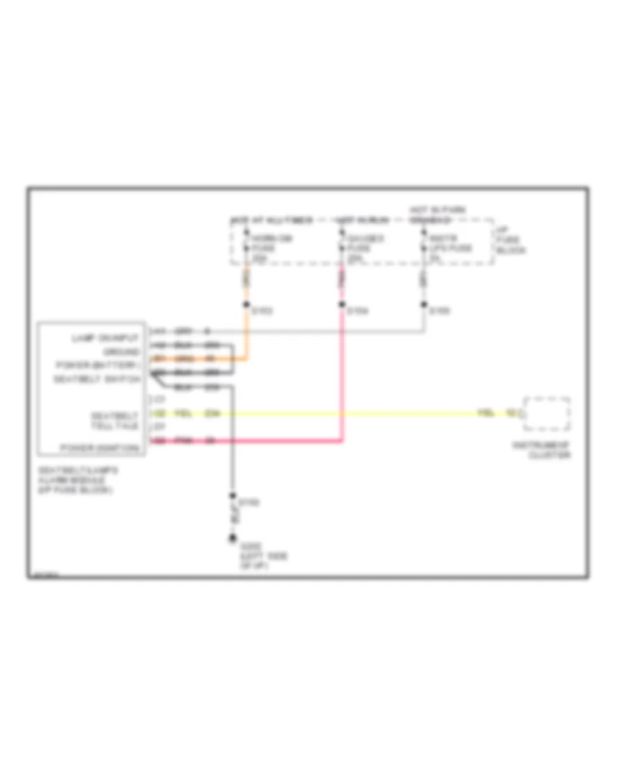
ПРЕДУПРЕЖДАЮЩИЕ СИСТЕМЫ
Электросхема предупреждающей системы, коммерческое шасси для GMC Vandura P1997 3500
Электросхема предупреждающей системы, коммерческое шасси для GMC Vandura P1997 3500 - Список элементов:
- (left interior bulkhead, near relay bracket)
- Dash lamps
- Diesel
- Fasten belts lamp
- G114 (a/t) (rear of left cylinder head)
- G119 (m/t) (generator bracket)
- G131 (thermostat housing)
- G202 (body builder instld)
- Gas
- Gauges fuse 20a
- Ground
- Horn dm fuse 20a
- Hot at all times
- Hot in park or head
- Hot in run or start
- I/p fuse block
- Instrument cluster
- Instrument lps fuse 5a
- Pnk
- Power (battery)
- Power (ignition)
- S143
- S143 (a/t) s118 (m/t)
- S204
- S205
- S207
- S209
- Seat belt input
- Seat belt lamp output
- Seat belt/lamps alarm (i/p fuse block)
Электросхема предупреждающей системы, шасси кэмпинга для GMC Vandura P1997 3500
Электросхема предупреждающей системы, шасси кэмпинга для GMC Vandura P1997 3500 - Список элементов:
- G202 (left side of i/p)
- Gauges fuse 20a
- Ground
- Horn dm fuse 20a
- Hot at all times
- Hot in park or head
- Hot in run
- I/p fuse block
- Instr lps fuse 5a
- Instrument cluster
- Lamp on input
- Pnk
- Power (battery)
- Power (ignition)
- S150
- S153
- S154
- S155
- Seatbelt switch
- Seatbelt tell tale
- Seatbelt/lamps alarm module (i/p fuse block)
ПРИБОРНАЯ ПАНЕЛЬ
Электросхема панели приборов, коммерческое шасси для GMC Vandura P1997 3500
Электросхема панели приборов, коммерческое шасси для GMC Vandura P1997 3500 - Список элементов:
- (diesel a/t: rear of left
- (gasoline a/t: thermostat
- (i/p harn, 16 cm from fuse block breakout)
- (i/p harn, 24 cm from fuse block breakout)
- (m/t) (a/t)
- (m/t: on generator
- (on left bulkhead)
- (w/ m/t) (diesel w/ a/t)
- (w/ m/t) (diesel w/ a/t) (gasoline w/ a/t)
- 1.5k
- 150 (m/t)
- 450 (a/t)
- Acc
- Anti-lock brakes system
- Batt
- Bracket)
- C111
- Coolant temperature gauge
- Cylinder head)
- Daytime running lamps control module (near steering column)
- Daytime running lights ind. (w/ drl)
- Diesel
- Diode network (15 cm from i/p fuse block)
- Ecm-1 fuse 20a
- Electronic brake control module (below radiator)
- Eng-1 fuse 20a
- Engine controls system (diesel only)
- Engine controls system (gasoline only)
- Engine coolant level switch (diesel only) (lower left end of surge tank)
- Engine coolant temperature gauge sender (left side of engine)
- Engine oil pressure gauge sender (top left rear of engine)
- Exterior lights system
- Fasten belts ind.
- Fuel gauge
- Fuel pump switch & engine oil pressure gauge sensor (top left rear of engine)
- Fuel sender & fuel pump (top of fuel tank)
- Fuel sender (top of fuel tank)
- G119 g114
- G119 g114 (m/t: generator bracket) (a/t: rear of left
- G119 g114 g125
- G125 (thermostat housing)
- G202
- G202 (on left bulkhead)
- Gasoline
- Gauges fuse 20a
- Glow plugs ind. (diesel)
- Gnd
- Headlights system
- Headlights system (w/ drl)
- Hi beam ind.
- Horn dm fuse 20a
- Hot at all times
- Hot in run or start
- Housing)
- I/p fuse block
- I/p fuse panel
- Ign
- Ign feed
- Ignition switch
- Illumination lamps
- Ind ctrl
- Instrument cluster
- Interior lights system
- Left turn ind.
- Lock
- Low coolant ind. (diesel)
- Low flow
- Low pres.
- Nca
- Off
- Oil pressure gauge
- P/b booster fluid flow & pressure alarm
- P/b booster fluid flow indicator/ alarm delay module
- P/b booster fluid flow indicator/ alarm switch
- P/b booster pump pressure switch
- Park brake in
- Park brake ind.
- Park brake indicator switch (park brake support bracket)
- Pnk
- Resistor r200 (near i/p fuse block)
- Right turn ind.
- S108
- S110
- S118
- S118 s143
- S138
- S143
- S162
- S205
- S207
- S216
- S217
- Service brake ind.
- Service engine soon ind.
- Service transmission ind. (diesel)
- Speedometer
- Start
- Sw sense
- Tan
- Transmission control module (left bulkhead)
- Transmissions system
- Twisted pair
- Vehicle control module (on left radiator support)
- Vehicle speed sensor (left rear of transmission)
- Vehicle speed sensor buffer (diesel only) (behind left side of i/p)
- Vehicle speed sig
- Voltmeter
- Vss out
- Vss rtn
- Vss sig
- W/ a/t only
- W/ drl
- W/ z49
- W/o z49
- Warning system
- Water in fuel ind. (diesel)
- Water-in-fuel sensor (diesel only) (rear of intake manifold)
Электросхема панели приборов, шасси кэмпинга (1 из 2) для GMC Vandura P1997 3500
Электросхема панели приборов, шасси кэмпинга (1 из 2) для GMC Vandura P1997 3500 - Список элементов:
- (5 bulbs)
- (abs harn, 11 cm from abs ground breakout)
- (body builder installed)
- (i/p harn, 70 cm from fuse block)
- (i/p harn, near fuse panel)
- (l19 only)
- (l19/l65)
- (l65 only)
- (l65) (l19)
- (under left side of i/p)
- Abs ind.
- Acc
- Anti-lock brake system
- Auto park ind.
- Coolant temperature gauge
- Daytime running lamps control module (near steering column)
- Daytime running lights ind. (w/ drl)
- Diesel
- Diode network
- Ecm-1 fuse 20a
- Electronic brake control module (on abs cross member)
- Eng-1 fuse 20a
- Engine controls system
- Engine controls system (diesel only)
- Engine coolant level switch (diesel only) (lower left end of surge tank)
- Engine oil pressure gauge sender (top left rear of engine)
- Exterior lights system
- Fasten belts ind.
- Fuel gauge
- Fuel pump switch & engine oil pressure gauge sensor (front left side of engine)
- G202
- G202 (under left side of i/p)
- Gages fuse 20a
- Gasoline
- Glow plugs ind. (diesel)
- Gnd
- Headlights system
- Headlights system (w/ drl)
- Hi beam ind.
- Hot in run
- Hot in run or start
- I/p fuse block
- Ign
- Ign feed
- Ignition switch
- Illumination lamps
- Ind ctrl
- Instrument cluster
- Interior lights system
- L19 & l65
- L19/165
- L29
- Left turn ind.
- Lock
- Low coolant ind. (diesel)
- Off
- Oil pressure gauge
- Park brake in
- Park brake ind.
- Park brake indicator switch (park brake bracket support)
- Pnk
- Provision for body builder
- Red
- Right turn ind.
- S121
- S126
- S128
- S135
- S149
- S150
- S154
- S162
- S165 (i/p harn, 18 cm from headlamp switch breakout)
- S166
- S203
- Service engine soon ind.
- Service throttle soon ind. (diesel)
- Speedometer
- Start
- Tan
- Twisted pair
- Vehicle control module (l29 only) (on left radiator support)
- Vehicle speed sensor (left rear side of transmission)
- Vehicle speed sensor buffer (l19/l65 only) (behind left side of i/p)
- Voltmeter
- Vss (hi)
- Vss (lo)
- Vss out
- Vss rtn
- Vss sig
- W/ drl
- W/ z49
- W/o z49
- Warning system
- Water in fuel ind. (diesel)
- Water-in-fuel sensor (diesel only) (part of fuel injection pump)
Электросхема панели приборов, шасси кэмпинга (2 из 2) для GMC Vandura P1997 3500
Электросхема панели приборов, шасси кэмпинга (2 из 2) для GMC Vandura P1997 3500 - Список элементов:
- (body builder installed)
- 1200- 1600 psi
- <450psi
- Battery junction block
- Diesel
- Diode d300
- Diode d301
- Engine coolant temperature gauge sender (front of engine)
- Fuel level sender (top of fuel tank)
- Fuel sender & fuel pump (top of fuel tank)
- Gasoline
- Hot at all times
- Hot in run
- I/p auxiliary fuse block
- Park
- Park brake low pressure switch (on right frame rail behind transmission)
- Park brake pressure valve solenoid
- Park brake pump motor (on right frame rail behind transmission)
- Park brake pump motor relay (on right frame rail behind transmission)
- Park brake pump motor switch (on right frame rail behind transmission)
- Pnk
- Red
- S115
- S364
СИСТЕМА АНТИБЛОКИРОВОЧНОЙ ТОРМОЗНОЙ СИСТЕМЫ ABS
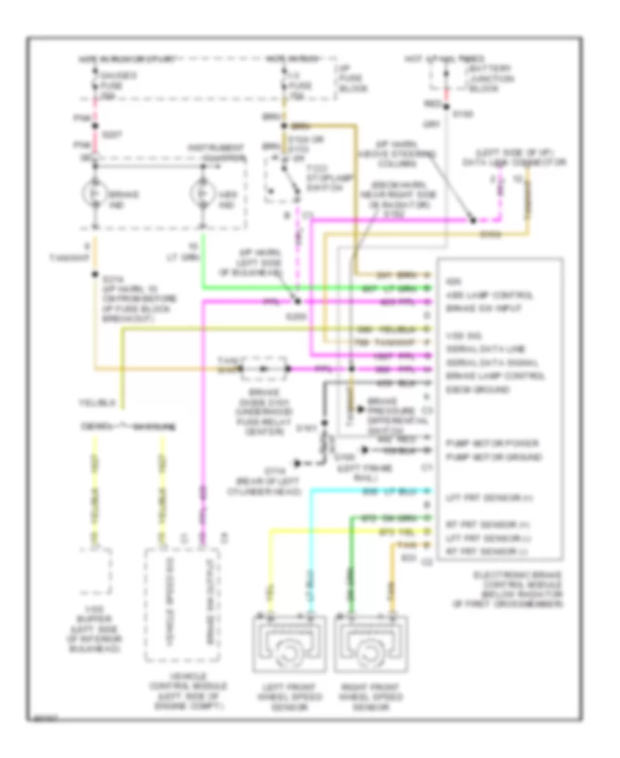
Электросхема антиблокировочной тормозной системы АБС (ABS), коммерческое шасси для GMC Vandura P1997 3500
Электросхема антиблокировочной тормозной системы АБС (ABS), коммерческое шасси для GMC Vandura P1997 3500 - Список элементов:
- (ebcm harn, near right side of radiator)
- (i/p harn, above steering column)
- (i/p harn, left side of bulkhead)
- (left frame rail)
- (left side of i/p) data link connector
- (rear of left cylinder head)
- Abs ind
- Abs lamp control
- Battery junction block
- Brake diode d101 (underhood fuse-relay center)
- Brake ind
- Brake lamp control
- Brake pressure differential switch
- Brake sw input
- Brake sw output
- C1 tcc/ stoplamp switch
- Diesel
- Ebcm ground
- Electronic brake control module (below radiator of first crossmember)
- G100
- G114
- Gasoline
- Gauges fuse 20a
- Hot at all times
- Hot in run
- Hot in run or start
- I-3 fuse 15a
- I/p fuse block
- Ign
- Instrument cluster
- Left front wheel speed sensor
- Lft frt sensor (+)
- Lft frt sensor (-)
- Pnk
- Pump motor ground
- Pump motor power
- Red
- Right front wheel speed sensor
- Rt frt sensor (+)
- Rt frt sensor (-)
- S150
- S160
- S161
- S162
- S200
- S207
- S214 (i/p harn, 10 cm from before i/p fuse block breakout)
- Serial data line
- Serial data signal
- Tan
- Vehicle control module (left side of engine compt)
- Vehicle speed sig
- Vss buffer (left side of interior bulkhead)
- Vss sig
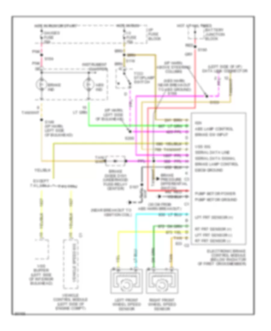
Электросхема антиблокировочной тормозной системы АБС (ABS), шасси кэмпинга для GMC Vandura P1997 3500
Электросхема антиблокировочной тормозной системы АБС (ABS), шасси кэмпинга для GMC Vandura P1997 3500 - Список элементов:
- (30 cm from abs harn breakout)
- (abs harn, near breakout to abs ground)
- (i/p harn, above steering column)
- (i/p harn, left side of bulkhead)
- (left side of i/p) data link connector
- (near breakout to ignition coil)
- 7.4 l vin j
- Abs ind
- Abs lamp control
- Battery junction block
- Brake diode d101 (underhood fuse-relay center)
- Brake ind
- Brake lamp control
- Brake pressure differential switch
- Brake sw input
- Ebcm ground
- Electronic brake control module (below radiator of first crossmember)
- Except 7.4 l vin j
- Gauges fuse 20a
- Hot at all times
- Hot in run
- Hot in run or start
- I-3 fuse 15a
- I/p fuse block
- Ign
- Instrument cluster
- Left front wheel speed sensor
- Lft frt sensor (+)
- Lft frt sensor (-)
- Pnk
- Pump motor ground
- Pump motor power
- Red
- Right front wheel speed sensor
- Rt frt sensor (+)
- Rt frt sensor (-)
- S149 (i/p harn, left side of bulkhead)
- S150
- S154
- S160
- S166
- S167
- S200
- Serial data line
- Serial data signal
- Tan
- Tcc/ stoplamp switch
- Vehicle control module (left side of engine compt)
- Vehicle speed sig
- Vss buffer (left side of interior bulkhead)
- Vss sig
СИСТЕМА КОНДИЦИОНЕРА
4.3L
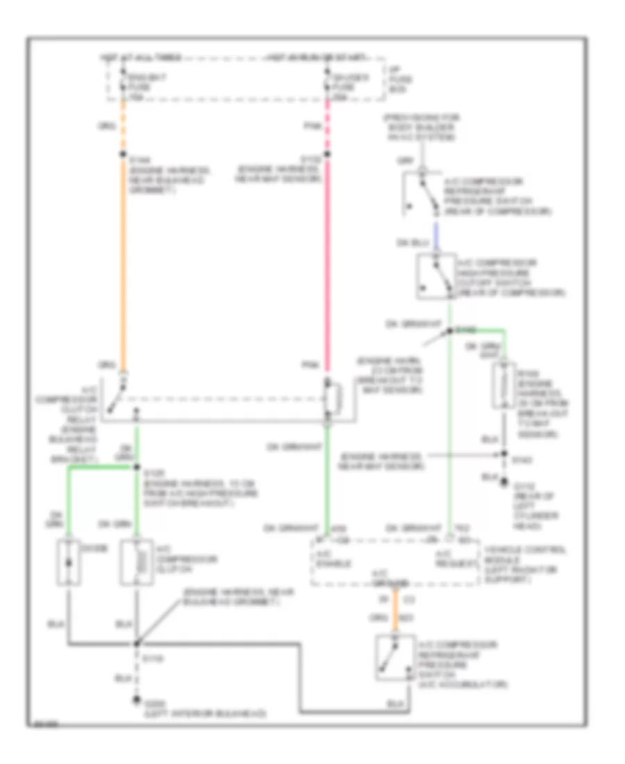
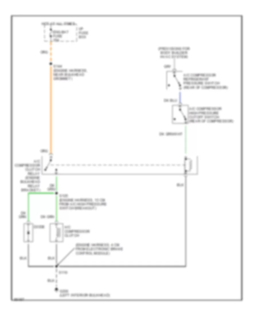
4.3L (VIN W), Электросхема кондиционера для GMC Vandura P1997 3500
4.3L (VIN W), Электросхема кондиционера для GMC Vandura P1997 3500 - Список элементов:
- (engine harn, 23 cm from breakout to maf sensor)
- (engine harness, near bulkhead grommet)
- (engine harness, near maf sensor)
- (provisions for body builder hvac system)
- A/c compressor clutch
- A/c compressor clutch relay (engine bulkhead relay bracket)
- A/c compressor high pressure cutoff switch (rear of compressor)
- A/c compressor refrigerant pressure switch (a/c accumulator)
- A/c compressor refrigerant pressure switch (rear of compressor)
- A/c enable
- A/c ground
- A/c request
- Diode
- Eng-bat fuse 15a
- G112 (rear of left cylinder head)
- G200 (left interior bulkhead)
- Gauges fuse 20a
- Hot at all times
- Hot in run or start
- I/p fuse box
- Pnk
- R100 (engine harness, 30 cm from break-out to maf
- S110
- S125 (engine harness, 13 cm from a/c high pressure switch breakout)
- S132 (engine harness, near maf sensor)
- S142
- S143
- S144 (engine harness, near bulkhead grommet)
- Sensor)
- Vehicle control module (left radiator support)
5.7L
5.7L (VIN R), Электросхема кондиционера для GMC Vandura P1997 3500
5.7L (VIN R), Электросхема кондиционера для GMC Vandura P1997 3500 - Список элементов:
- (engine harn, 23 cm from breakout to maf sensor)
- (engine harness, near bulkhead grommet)
- (engine harness, near maf sensor)
- (provisions for body builder hvac system)
- A/c compressor clutch
- A/c compressor clutch relay (engine bulkhead relay bracket)
- A/c compressor high pressure cutoff switch (rear of compressor)
- A/c compressor refrigerant pressure switch (a/c accumulator)
- A/c compressor refrigerant pressure switch (rear of compressor)
- A/c enable
- A/c ground
- A/c request
- Diode
- Eng-bat fuse 15a
- G112 (rear of left cylinder head)
- G200 (left interior bulkhead)
- Gauges fuse 20a
- Hot at all times
- Hot in run or start
- I/p fuse box
- Pnk
- R100 (engine harness, 30 cm from break-out to maf
- S110
- S125 (engine harness, 13 cm from a/c high pressure switch breakout)
- S132 (engine harness, near maf sensor)
- S142
- S143
- S144 (engine harness, near bulkhead grommet)
- Sensor)
- Vehicle control module (left radiator support)
6.5L
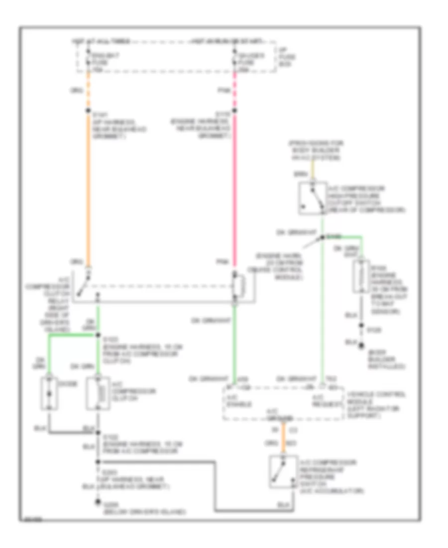
6.5L (VIN F), Электросхема кондиционера для GMC Vandura P1997 3500
6.5L (VIN F), Электросхема кондиционера для GMC Vandura P1997 3500 - Список элементов:
- (body builder installed)
- (engine harn, 20 cm from cruise control module)
- (provisions for body builder hvac system)
- A/c compressor clutch
- A/c compressor clutch relay (right side of driver's island)
- A/c compressor high pressure cutoff switch (in high pressure line)
- A/c compressor refrigerant pressure switch (rear of compressor)
- A/c enable
- A/c request
- Diode
- Eng-bat fuse 15a
- G206 (below driver's island)
- Gauges fuse 20a
- Hot at all times
- Hot in run or start
- I/p fuse box
- Pnk
- Powertrain control module (left side of driver's island)
- R100 (engine harness, 30 cm from break-out to maf
- S115 (engine harness, near bulkhead grommet)
- S122 (engine harness, 15 cm from a/c compressor
- S123 (engine harness, 15 cm from a/c compressor clutch)
- S126
- S140
- S141 (i/p harness, near bulkhead grommet)
- S203 (i/p harness, near bulkhead grommet)
- Sensor)
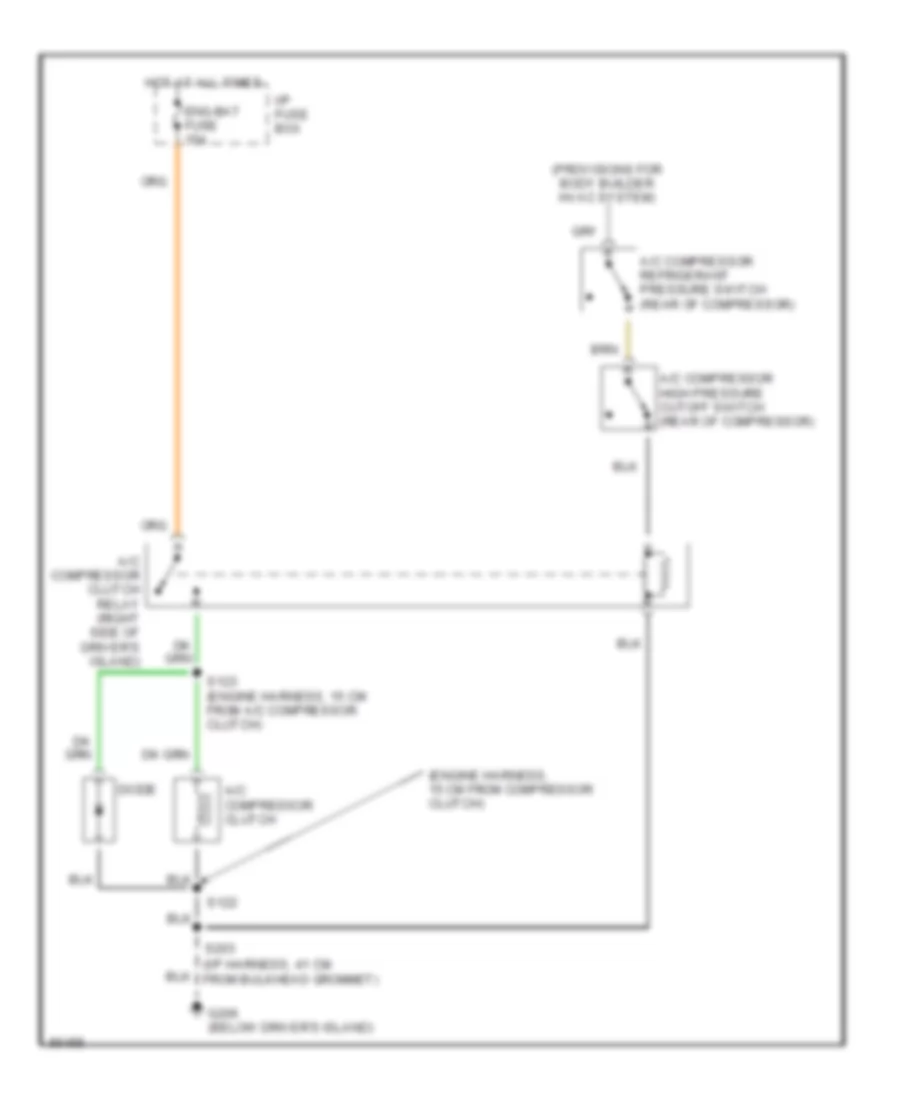
6.5L (VIN Y), Электросхема кондиционера для GMC Vandura P1997 3500
6.5L (VIN Y), Электросхема кондиционера для GMC Vandura P1997 3500 - Список элементов:
- (engine harness, 4 cm from electronic brake control module)
- (provisions for body builder hvac system)
- A/c compressor clutch
- A/c compressor clutch relay (engine bulkhead relay bracket)
- A/c compressor high pressure cutoff switch (rear of compressor)
- A/c compressor refrigerant pressure switch (rear of compressor)
- Diode
- Eng-bat fuse 15a
- G200 (left interior bulkhead)
- Hot at all times
- I/p fuse box
- S110
- S125 (engine harness, 13 cm from a/c high pressure switch breakout)
- S144 (engine harness, near bulkhead grommet)
7.4L
7.4L (VIN J), Электросхема кондиционера для GMC Vandura P1997 3500
7.4L (VIN J), Электросхема кондиционера для GMC Vandura P1997 3500 - Список элементов:
- (body builder installed)
- (engine harn, 20 cm from cruise control module)
- (provisions for body builder hvac system)
- A/c compressor clutch
- A/c compressor clutch relay (right side of driver's island)
- A/c compressor high pressure cutoff switch (rear of compressor)
- A/c compressor refrigerant pressure switch (a/c accumulator)
- A/c enable
- A/c ground
- A/c request
- Diode
- Eng-bat fuse 15a
- G206 (below driver's island)
- Gauges fuse 20a
- Hot at all times
- Hot in run or start
- I/p fuse box
- Pnk
- R100 (engine harness, 30 cm from break-out to maf
- S115 (engine harness, near bulkhead grommet)
- S122 (engine harness, 15 cm from a/c compressor
- S123 (engine harness, 15 cm from a/c compressor clutch)
- S126
- S140
- S141 (i/p harness, near bulkhead grommet)
- S203 (i/p harness, near bulkhead grommet)
- Sensor)
- Vehicle control module (left radiator support)
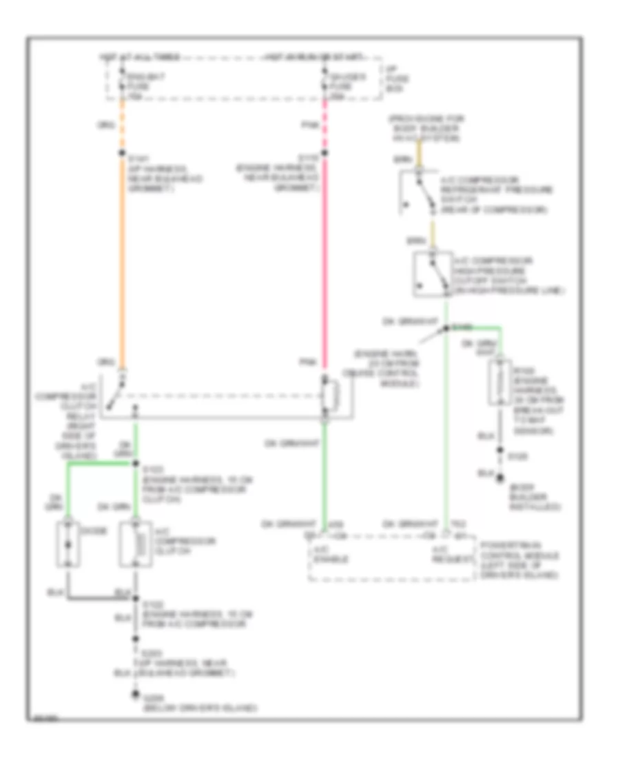
7.4L (VIN N), Электросхема кондиционера для GMC Vandura P1997 3500
7.4L (VIN N), Электросхема кондиционера для GMC Vandura P1997 3500 - Список элементов:
- (engine harness, 15 cm from compressor clutch)
- (i/p harness, 41 cm from bulkhead grommet)
- (provisions for body builder hvac system)
- A/c compressor clutch
- A/c compressor clutch relay (right side of driver's island)
- A/c compressor high pressure cutoff switch (rear of compressor)
- A/c compressor refrigerant pressure switch (rear of compressor)
- Diode
- Eng-bat fuse 15a
- G206 (below driver's island)
- Hot at all times
- I/p fuse box
- S122
- S123 (engine harness, 15 cm from a/c compressor clutch)
- S203
СИСТЕМА КРУИЗКОНТРОЛЯ
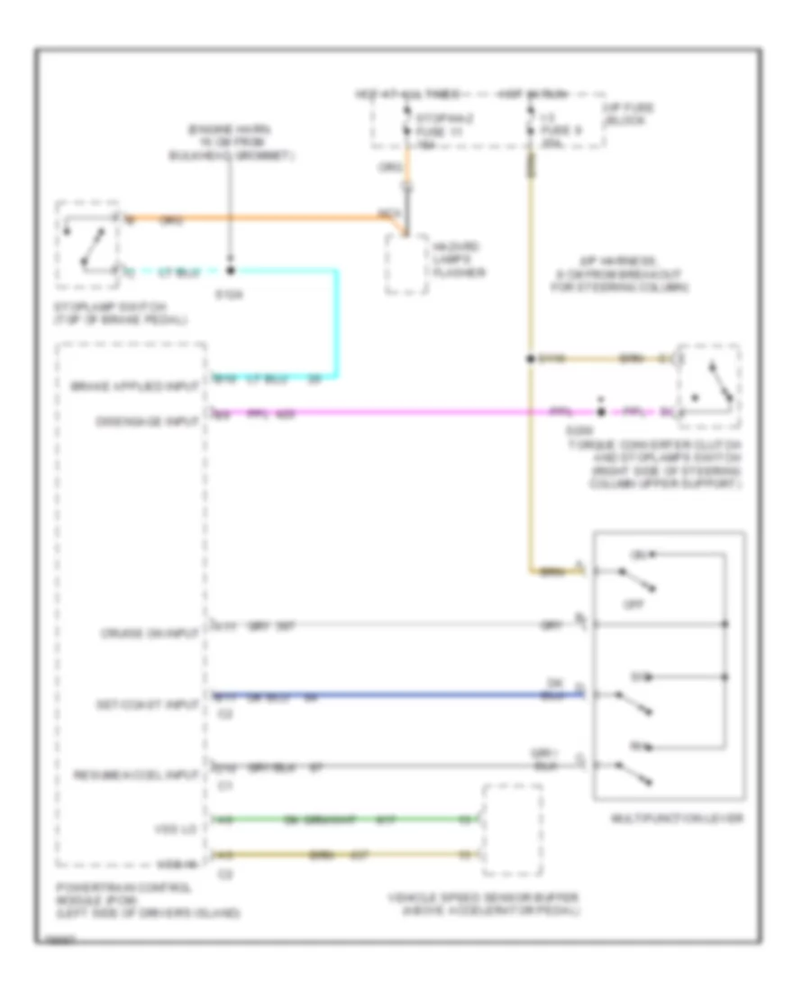
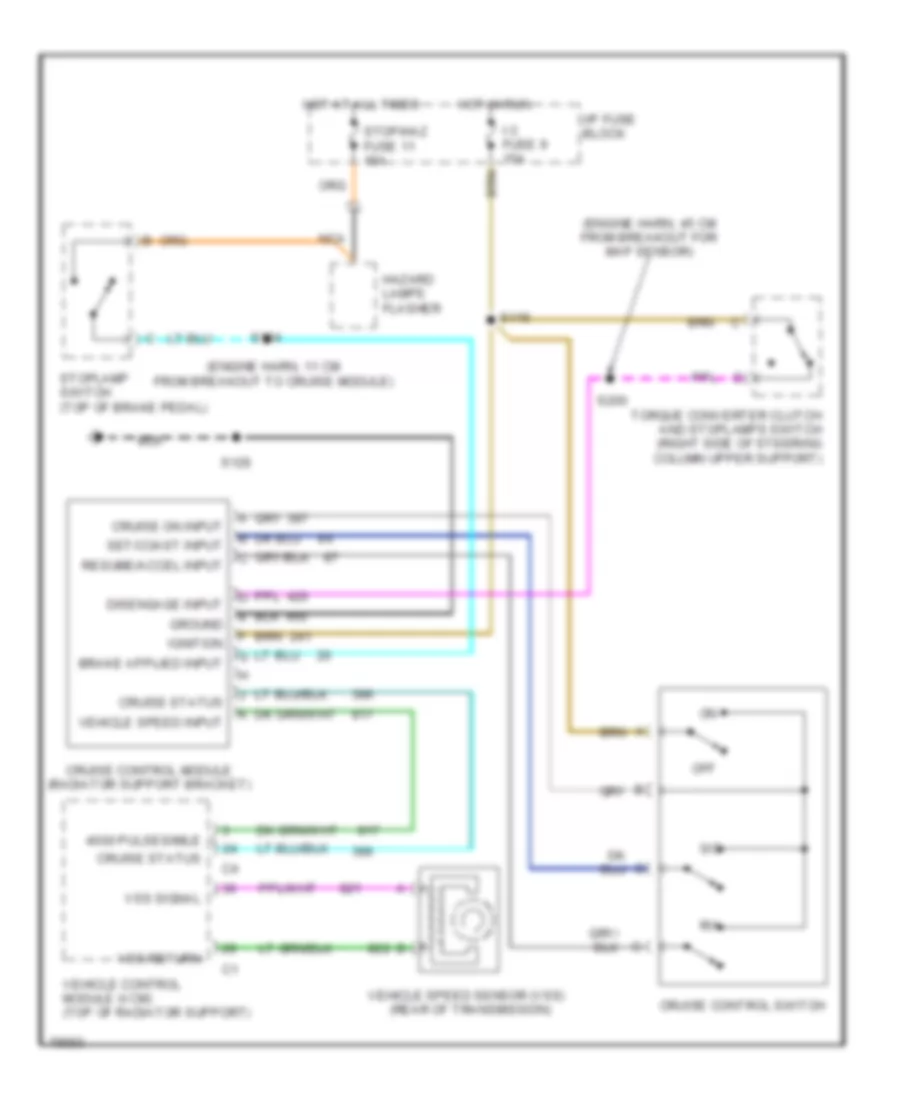
6.5L
6.5L (VIN F), Электросхема системы круизконтроля, шасси кэмпинга для GMC Vandura P1997 3500
6.5L (VIN F), Электросхема системы круизконтроля, шасси кэмпинга для GMC Vandura P1997 3500 - Список элементов:
- (engine harn, 16 cm from bulkhead grommet)
- (i/p harness, 8 cm from breakout for steering column)
- A11
- B10
- B11
- Cruise on input
- D10
- Disengage input
- Hazard lamps flasher
- Hot at all times
- Hot in run
- I-3 fuse 9 15a
- I/p fuse block
- Multifunction lever
- Nca
- Off
- Powertrain control module (pcm) (left side of driver's island)
- R/a
- Resume/accel input
- S/c
- S116
- S124
- S200
- Set/coast input
- Stop/haz fuse 11 15a
- Stoplamp switch (top of brake pedal)
- Torque converter clutch and stoplamps switch (right side of steering column upper support)
- Vehicle speed sensor buffer (above accelerator pedal)
- Vss hi
- Vss lo
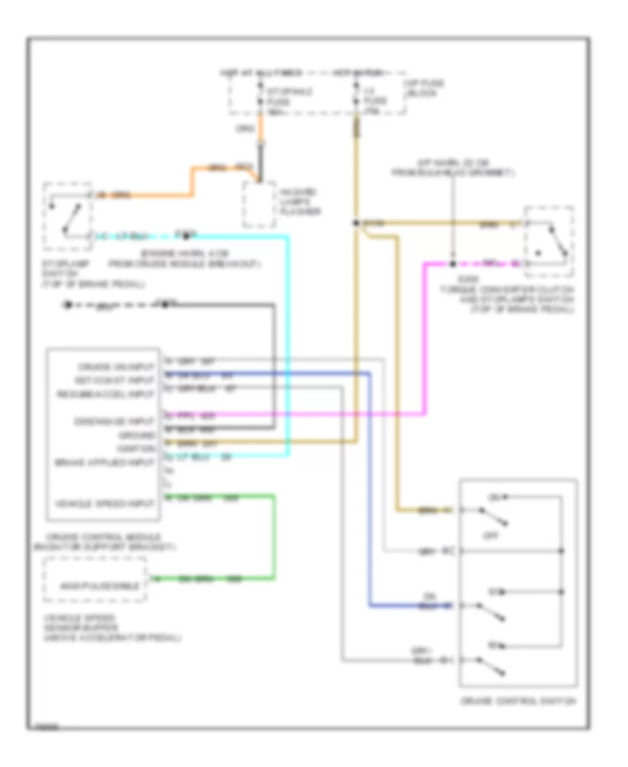
7.4L
7.4L (VIN J), Электросхема системы круизконтроля, шасси кэмпинга для GMC Vandura P1997 3500
7.4L (VIN J), Электросхема системы круизконтроля, шасси кэмпинга для GMC Vandura P1997 3500 - Список элементов:
- (engine harn, 11 cm from breakout to cruise module)
- (engine harn, 45 cm from breakout for map sensor)
- (rear of transmission)
- 4000 pulses/mile
- Cruise control module (radiator support bracket)
- Cruise control switch
- Cruise on input
- Cruise status
- Disengage input
- Ground
- Hazard lamps flasher
- Hot at all times
- Hot in run
- I-3 fuse 9 15a
- I/p fuse block
- Ignition
- Nca
- Off
- R/a
- Resume/accel input
- S/c
- S116
- S124
- S126
- S200
- Set/coast input
- Stop/haz fuse 11 15a
- Stoplamp switch (top of brake pedal)
- Torque converter clutch and stoplamps switch (right side of steering column upper support)
- Vehicle control module (vcm) (top of radiator support)
- Vehicle speed input
- Vehicle speed sensor (vss)
- Vss return
- Vss signal
7.4L (VIN N), Электросхема системы круизконтроля, шасси кэмпинга для GMC Vandura P1997 3500
7.4L (VIN N), Электросхема системы круизконтроля, шасси кэмпинга для GMC Vandura P1997 3500 - Список элементов:
- (engine harn, 4 cm from cruise module breakout)
- (i/p harn, 22 cm from bulkhead grommet)
- 4000 pulses/mile
- Cruise control module (radiator support bracket)
- Cruise control switch
- Cruise on input
- Disengage input
- Ground
- Hazard lamps flasher
- Hot at all times
- Hot in run
- I-3 fuse 15a
- I/p fuse block
- Ignition
- Nca
- Off
- R/a
- Resume/accel input
- S/c
- S116
- S124
- S126
- S200
- Set/coast input
- Stop/haz fuse 15a
- Stoplamp switch (top of brake pedal)
- Torque converter clutch and stoplamps switch (top of brake pedal)
- Vehicle speed input
- Vehicle speed sensor buffer (above accelerator pedal)
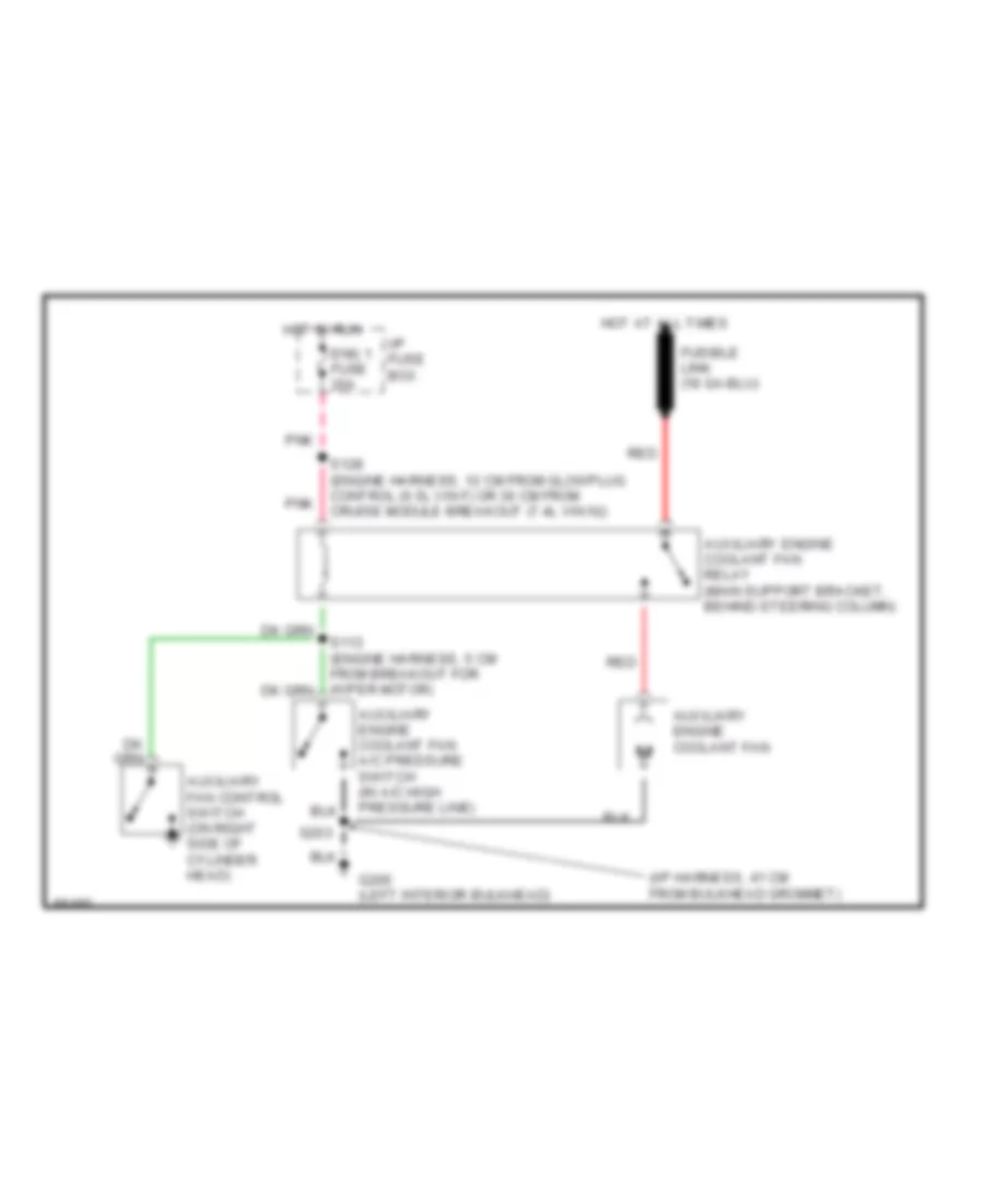
СИСТЕМА ОХЛАЖДЕНИЯ
6.5L
6.5L (VIN F), Электросхема системы охлаждения для GMC Vandura P1997 3500
6.5L (VIN F), Электросхема системы охлаждения для GMC Vandura P1997 3500 - Список элементов:
- (i/p harness, 41 cm from bulkhead grommet)
- Auxiliary engine coolant fan
- Auxiliary engine coolant fan a/c pressure switch (in a/c high pressure line)
- Auxiliary engine coolant fan relay (main support bracket, behind steering column)
- Auxiliary fan control switch (on right side of cylinder head)
- Eng 1 fuse 20a
- G200 (left interior bulkhead)
- Hot at all times
- Hot in run
- I/p fuse box
- Pnk
- Red
- S128 (engine harness, 12 cm from glowplug control (6.5l vin f) or 30 cm from cruise module breakout (7.4l vin n))
- S203
6.5L (VIN Y), Электросхема системы охлаждения для GMC Vandura P1997 3500
6.5L (VIN Y), Электросхема системы охлаждения для GMC Vandura P1997 3500 - Список элементов:
- Auxiliary engine coolant fan
- Auxiliary engine coolant fan a/c pressure switch (in a/c high pressure line)
- Auxiliary engine coolant fan relay (engine bulkhead relay bracket, under battery junction block)
- Eng 1 fuse 20a
- G200 (left interior bulkhead)
- Hot at all times
- Hot in run
- I/p fuse box
- Pnk
- Red
- S110 (engine harness, 4 cm from electronic brake control module)
- S116 (engine harness, 5 cm from right glow plug breakout)
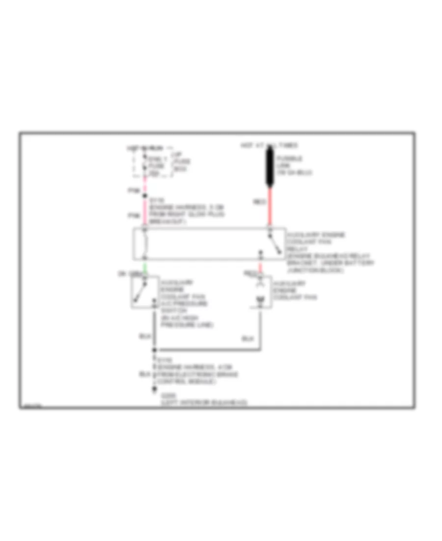
7.4L
7.4L (VIN J), Электросхема системы охлаждения для GMC Vandura P1997 3500
7.4L (VIN J), Электросхема системы охлаждения для GMC Vandura P1997 3500 - Список элементов:
- (i/p harness, 41 cm from bulkhead grommet)
- Auxiliary engine coolant fan
- Auxiliary engine coolant fan a/c pressure switch (in a/c high pressure line)
- Auxiliary engine coolant fan relay (main support bracket, behind steering column)
- Eng 1 fuse 20a
- G200 (left interior bulkhead)
- Hot at all times
- Hot in run
- I/p fuse box
- Pnk
- Red
- S128 (engine harness, 12 cm from egr breakout)
- S203
- Vehicle control module (top of radiator support)
7.4L (VIN N), Электросхема системы охлаждения для GMC Vandura P1997 3500
7.4L (VIN N), Электросхема системы охлаждения для GMC Vandura P1997 3500 - Список элементов:
- (i/p harness, 41 cm from bulkhead grommet)
- Auxiliary engine coolant fan
- Auxiliary engine coolant fan a/c pressure switch (in a/c high pressure line)
- Auxiliary engine coolant fan relay (main support bracket, behind steering column)
- Auxiliary fan control switch (on right side of cylinder head)
- Eng 1 fuse 20a
- G200 (left interior bulkhead)
- Hot at all times
- Hot in run
- I/p fuse box
- Pnk
- Red
- S128 (engine harness, 12 cm from glowplug control (6.5l vin f) or 30 cm from cruise module breakout (7.4l vin n))
- S203
СИСТЕМА ПЕРЕДАЧИ ДАННЫХ
Электросхема компьютерной линии передачи данных CAN, коммерческое шасси для GMC Vandura P1997 3500
Электросхема компьютерной линии передачи данных CAN, коммерческое шасси для GMC Vandura P1997 3500 - Список элементов:
- (left interior bulkhead)
- (on rear of left cylinder head)
- (thermostat housing)
- B10
- Data clss 2
- Data link connector (left side of interior bulkhead, on right side of relay bracket)
- Diesel
- Electronic brake control module (below radiator)
- Eng bat fuse 15a
- G110
- G114
- G202
- Gasoline
- Hot at all times
- I/p fuse block
- S110
- S143
- S144
- S150 (i/p harness, approx 17 cm from breakout to steering column connector)
- Serial data
- Tan
- Transmission control module (diesel a/t only) (left interior bulkhead, on top of relay bracket)
- Vehicle control module (gasoline only) (left radiator support)
Электросхема компьютерной линии передачи данных CAN, шасси кэмпинга для GMC Vandura P1997 3500
Электросхема компьютерной линии передачи данных CAN, шасси кэмпинга для GMC Vandura P1997 3500 - Список элементов:
- 6.5l
- 6.5l vin f
- 7.4l vin j
- 7.4l vin j & 6.5l vin f only
- A14
- Data clss 2
- Data link connector (left side support bracket of steering column)
- Diag enable
- Diag sig
- Electronic brake control module (abs crossmember)
- Eng bat fuse 15a
- G112 (20 cm from left glow plug harness breakout)
- G120 (10 cm from alternator harness breakout)
- G202 (left side of i/p)
- Hot at all times
- I/p fuse block
- Powertrain control module (6.5l vin f only) (left side of driver's island)
- Powertrain control module (7.4l vin n only) (left side of driver's island)
- S126
- S141
- S202 (i/p harness, 15 cm from breakout for abs harness)
- S203
- Serial data
- Tan
- Vehicle control module (7.4l vin j only) (top of radiator support)
СИСТЕМА УПРАВЛЕНИЯ ДВИГАТЕЛЯ
4.3L
4.3L (VIN W), Электросхема системы управления двигателя коммерческое шасси (1 из 4) для GMC Vandura P1997 3500
4.3L (VIN W), Электросхема системы управления двигателя коммерческое шасси (1 из 4) для GMC Vandura P1997 3500 - Список элементов:
- (thermostat housing) g125
- 1-2 shift sol ctrl
- 2-3 shift sol ctrl
- 3x ckp sens sig
- A pnk
- A/c cmp cltch rly out
- A/c compressor clutch relay (engine bulkhead relay bracket, under battery junction block)
- Cam posit sens rtn
- Cam posit sens sig
- Camshaft position (cmp) sensor (in distributor)
- Ckp sens rtn
- Crankshaft position (ckp) sensor (right front of engine at crankshaft balancer pulley)
- Ect sensor input
- Egr posit input
- Evap can purge ctrl
- Evaporative emissions (evap) canister purge solenoid valve (right center of intake manifold)
- Feed ign a pnk
- Fuel inj no.1 ctrl
- Fuel inj no.2 ctrl
- Fuel inj no.3 ctrl
- Fuel inj no.4 ctrl
- Fuel inj no.5 ctrl
- Fuel inj no.6 ctrl
- G125 (thermostat housing)
- Hall effect sensor
- Heated oxygen sensor (ho2s) left pre-convertor (left exhaust pipe ahead of catalytic converter)
- Ho2s bnk1 sens1 gnd
- Ho2s bnk1 sens1 sig
- Ho2s bnk2 sens1 gnd
- Ho2s bnk2 sens1 sig
- Ho2s post sens2 gnd
- Ho2s post sens2 sig
- Iat sens sig
- Idle air control (iac) valve (left side of air intake system)
- Idle air ctrl (a-low)
- Idle air ctrl (b-low)
- Idle air ctrl (iac) a-hi
- Idle air ctrl (iac) b-hi
- Knock sens sig
- Knock sensor (ks) (rear of engine, top center)
- Map sensor input
- Mass air flow input
- Nca
- Pnk
- Pnk c
- Pnk d
- Power
- S110
- S138
- S140
- S143
- Sens gnd
- System ground
- Tan
- Tcc pwm sol ctrl
- Tft sig
- Throttle position sens
- Vehicle control module (vcm) (vcm bracket bolted to left radiator support)
- Vehicle speed sensor (vss) (left rear of transmission, near center)
- Vss rtn
- Vss sig
- Whl spd sig, left frt
4.3L (VIN W), Электросхема системы управления двигателя коммерческое шасси (2 из 4) для GMC Vandura P1997 3500
4.3L (VIN W), Электросхема системы управления двигателя коммерческое шасси (2 из 4) для GMC Vandura P1997 3500 - Список элементов:
- (front left top of intake manifold) linear exhaust gas recirculation (egr) valve
- (rear of left cylinder head) g114
- 1-2 shift solenoid
- 2-3 shift solenoid
- Automatic transmission (a/t) (if equipped) (rear of engine)
- Ecm-i fuse 20a
- Eng 1 fuse 20a
- Fuel injector no.1
- Fuel injector no.2
- Fuel injector no.3
- Fuel injector no.4
- Fuel injector no.5
- Fuel injector no.6
- Heated oxygen sensor (h02s) post convertor (exhaust pipe behind catalytic converter)
- Heated oxygen sensor (ho2s) right pre-convertor (right exhaust pipe ahead of catalytic converter)
- Hot in (on) run & start (crank)
- I/p fuse block (dash panel provided by body builder) (body builder installed)
- Nca
- Note: (fuel injectors are located in central port injection, central sfi, in center of intake manifold, at fuel meter body)
- Pnk
- Pnk d
- Pnk n
- Pressure control solenoid (pcs)
- Red p
- S108
- S116
- S118
- Tan
- Tan a
- Tcc pwm solenoid
- Trans fuse 10a
- Transmission fluid temperature (tft) sensor (internal)
- Transmission range (tr) pressure switch assembly
- W/ a/t only
4.3L (VIN W), Электросхема системы управления двигателя коммерческое шасси (3 из 4) для GMC Vandura P1997 3500
4.3L (VIN W), Электросхема системы управления двигателя коммерческое шасси (3 из 4) для GMC Vandura P1997 3500 - Список элементов:
- (eng harn, approx 13cm from tps breakout) s137
- (eng harn, approx 8cm from ect sensor breakout)
- (eng harn, approx 8cm from tps breakout) s136
- (tail & stop lamps extension harness at crossmember in front of fuel tank) g415
- 5v ref
- A/c compressor high pressure cut-off switch (rear of a/c compressor)
- Eng bat fuse 15a
- Engine coolant temperature (ect) sensor (front of intake manifold near thermostat housing)
- Fuel gauge
- Fuel pump switch & engine oil pressure gauge sensor (top left rear of engine)
- Fuel sender & fuel pump (top of fuel tank)
- G114 (rear of left cylinder head)
- G125 (thermostat housing)
- G202 (left interior bulkhead near relay bracket) (body builder installed)
- Gauges fuse 20a
- Ground distribution system
- Hot at all times
- Hot in (on) run & start (crank)
- I/p fuse block (dash panel provided by body builder) (body builder installed)
- Instrument cluster
- Intake air temperature (iat) sensor (engine air induction system elbow near remote air cleaner)
- Manifold absolute pressure (map) sensor (intake manifold, rear center)
- Map
- Mass air flow sensor (maf) (air intake system between air cleaner & engine)
- Nca
- Oil press gauge
- Pnk
- R100 (1100 ohms .75 watts)
- Red
- Ref lo
- S118
- S118 (m/t)
- S119 (eng harn, approx 11cm from ect sensor breakout)
- S135
- S141
- S142 (eng harn, approx 23cm from maf sensor breakout)
- S143
- S143 (a/t)
- S144
- S207
- Service engine soon indicator
- Speedo meter
- Tan
- Tan a
- Temp
- Throttle position (tp) sensor (intake system, left side)
4.3L (VIN W), Электросхема системы управления двигателя коммерческое шасси (4 из 4) для GMC Vandura P1997 3500
4.3L (VIN W), Электросхема системы управления двигателя коммерческое шасси (4 из 4) для GMC Vandura P1997 3500 - Список элементов:
- (engine harness, taped to ignition coil breakout)
- (i/p side of eng harn, approx 19cm from left bulkhead grommet toward ignition sw)
- (left interior bulkhead near relay bracket) (body builder installed) g202
- (rear of left cylinder head) g114
- (thermostat housing) g125
- 5v ref
- 5v return
- 87a
- A/c request sig
- A/t
- A/t input speed sensor (transmission, left front)
- Anti-lock brake system
- Brake sig
- Clutch pedal position switch (left side of brake pedal bracket)
- Clutch sig
- Cylinder no.1
- Cylinder no.2
- Cylinder no.3
- Cylinder no.4
- Cylinder no.5
- Cylinder no.6
- Data link connector (dlc) (partial) (left interior bulkhead on right side of relay bracket)
- Distributor (top rear of engine)
- Ecm-bat fuse 20a
- Electronic ignition (ei) coil driver module (bracket at top edge of right cylinder head)
- Feed ignition
- Fuel pump prime connector (taped to fuel pump relay breakout)
- Fuel pump relay (engine bulkhead relay bracket under battery junction block)
- Fuel pump rly ctrl
- G125 (thermostat housing)
- Ground
- High voltage coil wire
- Hot at all times
- Hot in (on) run
- I-3 fuse 15a
- I/p fuse block (dash panel provided by body builder) (body builder installed)
- Ign feed
- Ignition coil (bracket at top edge of right cylinder head)
- Input spd sens rtn
- Input spd sens sig
- M/t
- M/t only
- Mil ctrl
- Pcs sol (hi)
- Pcs sol (lo)
- Pnk
- Pnk a
- Range sig "a"
- Range sig "b"
- Range sig "c"
- Red
- Return control timing
- S110
- S133
- S134
- S138
- S143
- S200
- Serial data
- Service circuit power
- Shift interlock system
- Signal control timing
- Spark plugs
- System ground
- Tachometer (provision for) a
- Timing ctrl sig
- Torque convertor clutch (tcc) & stop lamps switch (right side of steering column upper support)
- Vehicle control module (vcm) (vcm bracket bolted to left radiator support)
- Vss output
5.7L
5.7L (VIN R), Электросхема системы управления двигателя коммерческое шасси (1 из 4) для GMC Vandura P1997 3500
5.7L (VIN R), Электросхема системы управления двигателя коммерческое шасси (1 из 4) для GMC Vandura P1997 3500 - Список элементов:
- 1-2 shift sol ctrl
- 2-3 shift sol ctrl
- 4x ckp sens sig
- A pnk
- A/c cmp cltch rly out
- A/c compressor clutch relay (engine bulkhead relay bracket, under battery junction block)
- C pnk
- Cam posit sens rtn
- Cam posit sens sig
- Camshaft position (cmp) sensor (in distributor)
- Ckp sens rtn
- Ckp sensor return
- Ckp sensor signal
- Crankshaft position sensor (ckp) (right front of engine at crankshaft balancer pulley)
- Ect sensor in
- Egr posit in
- Evap can purge ctrl
- Evaporative emissions (evap) canister purge solenoid valve (right center of intake manifold)
- Fuel inj no.1 ctrl
- Fuel inj no.2 ctrl
- Fuel inj no.3 ctrl
- Fuel inj no.4 ctrl
- Fuel inj no.5 ctrl
- Fuel inj no.6 ctrl
- Fuel inj no.7 ctrl
- Fuel inj no.8 ctrl
- G125 (thermostat housing)
- Hall effect sensor
- Heated oxygen sensor (ho2s) left pre-convertor (left exhaust pipe ahead of catalytic converter)
- Heated oxygen sensor (ho2s) right pre-convertor (right exhaust pipe ahead of catalytic converter)
- Ho2s bnk1 sens1 gnd
- Ho2s bnk1 sens1 sig
- Ho2s bnk1 sens2 gnd
- Ho2s bnk1 sens2 sig
- Ho2s bnk2 sens1 gnd
- Ho2s bnk2 sens1 sig
- Ho2s bnk2 sens2 gnd
- Ho2s bnk2 sens2 sig
- Iat sens sig
- Idle air control (iac) valve (left side of air intake system)
- Idle air ctrl (a-low)
- Idle air ctrl (b-low)
- Idle air ctrl (iac) a-hi
- Idle air ctrl (iac) b-hi
- Ign feed
- Knock sens sig
- Knock sensor (ks) (engine block, lower right side in front of starter)
- Map sensor in
- Mass air flow in
- Nca
- Pnk
- Pnk d
- Pnk pnk
- Power
- S138
- S139
- S140
- Sens gnd
- Tan
- Tan a
- Tcc pwm sol ctrl
- Tft sig
- Throttle posit sens
- Vcm ground
- Vehicle control module (vcm) (vcm bracket bolted to left radiator support)
- Vehicle speed sensor (vss) (left rear of transmission, near center)
- Vss rtn
- Vss sig
5.7L (VIN R), Электросхема системы управления двигателя коммерческое шасси (2 из 4) для GMC Vandura P1997 3500
5.7L (VIN R), Электросхема системы управления двигателя коммерческое шасси (2 из 4) для GMC Vandura P1997 3500 - Список элементов:
- (rear of left cylinder head) g114
- 1-2 shift solenoid
- 2-3 shift solenoid
- Automatic transmission (a/t) (if equipped) (rear of engine)
- Ecm-1 fuse 20a
- Eng 1 fuse 20a
- Fuel injector no.1
- Fuel injector no.2
- Fuel injector no.3
- Fuel injector no.4
- Fuel injector no.5
- Fuel injector no.6
- Fuel injector no.7
- Fuel injector no.8
- Heated oxygen sensor (ho2s) left post convertor (left exhaust pipe behind catalytic converter)
- Heated oxygen sensor (ho2s) right post convertor (right exhaust pipe behind catalytic converter)
- Hot in (on) run & start (crank)
- I/p fuse block (dash panel provided by body builder) (body builder installed)
- Linear exhaust gas recirculation (egr) solenoid valve (front left top of intake manifold)
- Nca
- Note: fuel injectors are located in central port injection, center of intake manifold (fuel meter body)
- Pnk
- Pnk d
- Pnk n
- Pnk pnk pnk pnk
- Pressure control solenoid (pcs)
- Red p
- S108
- S116
- S118
- Tan
- Tan a
- Tcc pwm solenoid
- Transmission fluid temperature (tft) sensor (internal)
- Transmission range (tr) pressure switch assembly
5.7L (VIN R), Электросхема системы управления двигателя коммерческое шасси (3 из 4) для GMC Vandura P1997 3500
5.7L (VIN R), Электросхема системы управления двигателя коммерческое шасси (3 из 4) для GMC Vandura P1997 3500 - Список элементов:
- (eng harn, approx 30cm from maf sensor breakout)
- (eng harn, approx 8cm from ect sensor breakout) s135
- (engine harn, approx 8cm from tp sensor breakout)
- (tail & stop lamps extension harness at crossmember in front of fuel tank) g415
- 5v ref
- A/c compressor high pressure cut-off switch (rear of a/c compressor)
- Eng-bat fuse 15a
- Engine coolant temperature (ect) sensor (front of intake manifold, near thermostat housing)
- Fuel gauge
- Fuel pump switch & engine oil pressure gauge sensor (top left rear of engine)
- Fuel sender & fuel pump (top of fuel tank)
- G114 (rear of left cylinder head)
- G125 (thermostat housing)
- G202 (left interior bulkhead near relay bracket) (body builder installed)
- Gauges fuse 20a
- Hot at all times
- Hot in (on) run & start (crank)
- I/p fuse block (dash panel provided by body builder) (body builder installed)
- Instrument cluster
- Intake air temperature (iat) sensor (engine air induction system elbow near remote air cleaner)
- Manifold absolute pressure (map) sensor (intake manifold, rear center)
- Map
- Mass air flow (maf) sensor (air intake system between air cleaner & engine)
- Nca
- Oil press gauge
- Pnk
- R100 (1100 ohms .75 watts)
- Red
- Ref lo
- S118 (m/t)
- S119 (eng harn, approx 4cm from ect sensor breakout)
- S136
- S137 (eng harn, approx 12cm from tp sensor breakout)
- S141 (eng harn, approx 30cm from maf sensor breakout)
- S142
- S143
- S143 (a/t)
- S144
- S205
- S207
- Service engine soon indicator
- Speedo meter
- Tan
- Tan a
- Temp
- Throttle position (tp) sensor (intake system, left side)
- Trans fuse 10a
5.7L (VIN R), Электросхема системы управления двигателя коммерческое шасси (4 из 4) для GMC Vandura P1997 3500
5.7L (VIN R), Электросхема системы управления двигателя коммерческое шасси (4 из 4) для GMC Vandura P1997 3500 - Список элементов:
- (engine harness, taped to ignition coil breakout)
- (left interior
- (left interior bulkhead near relay bracket) (body builder installed) g202
- (rear of left cylinder head) g114
- 5v ref
- 5v rtn
- 87a
- A/c request sig
- A/t
- A/t input speed sensor (transmission, left front)
- Anti- lock brakes system
- Brake sig
- Bulkhead on right side of relay bracket)
- Clutch pedal position switch (left side of brake pedal bracket)
- Clutch sig
- Cylinder no.1
- Cylinder no.2
- Cylinder no.3
- Cylinder no.4
- Cylinder no.5
- Cylinder no.6
- Cylinder no.7
- Cylinder no.8
- Data link connector (dlc)
- Distributor (top rear of engine)
- Ecm-bat fuse 20a
- Electronic ignition coil driver module (bracket at top edge of right cylinder head)
- Evap can purge sw sig
- Evaporative emmissions (evap) canister purge vacuum diagnostic switch (right front of engine above valve cover)
- Fuel pump a prime connector (taped to fuel pump relay breakout)
- Fuel pump relay (engine bulkhead relay bracket under battery junction block)
- Fuel pump rly ctrl
- G125 (thermostat housing)
- Gnd
- Ground
- High voltage coil wire
- Hot at all times
- Hot in (on) run
- I-3 fuse 15a
- I/p fuse block (dash panel provided by body builder) (body builder installed)
- Ign feed
- Ignition coil (bracket at top edge of right cylinder head)
- Ignition feed
- Input spd sens rtn
- Input spd sens sig
- M/t
- Mil ctrl
- Pcs sol (hi)
- Pcs sol (lo)
- Pnk
- Pnk a
- Range sig "a"
- Range sig "b"
- Range sig "c"
- Red
- S110
- S133
- S134
- S138
- S143
- S200 (i/p side of eng harn, approx 19cm from left bulkhead grommet)
- Serial data
- Service circuit power
- Shift interlock system
- Spark plugs
- System gnd
- Tachometer (provision for) a
- Timing control return
- Timing control signal
- Timing ctrl sig
- Torque convertor clutch (tcc) & stop lamps switch (right side of steering column upper support)
- Vehicle control module (vcm) (vcm bracket bolted to left radiator support)
- Vss output
6.5L
6.5L (VIN F), Электросхема системы управления двигателя шасси кэмпинга (1 из 4) для GMC Vandura P1997 3500
6.5L (VIN F), Электросхема системы управления двигателя шасси кэмпинга (1 из 4) для GMC Vandura P1997 3500 - Список элементов:
- (18 cm from breakout for left glow plugs) g112
- (eng harn, 16cm from battery jb stud d)
- (eng harn, 21cm from left bulkhead grommet)
- 12v
- 3-2 shift sol
- 5 vref
- 5v ref volt
- A/c request sig
- A10
- A11 3 mode cruise a12
- B10
- B11
- B12
- Brake sw in
- Brake switch input
- C10
- C11
- C12
- C13
- C14
- C15
- C16
- Cam posit sens sig rtn
- Camshaft posit sens
- Closure gnd
- Coolant temperature sensor (lower left front of engine block)
- Cruise ctrl sw engage
- Cruise eng sw retard
- D10
- D11
- D12
- D13
- D14
- D15
- D16
- Ect temp sens in
- Engine crank sens input
- Engine crank sensor (inside electronic injection pump)
- Force motor
- Force mtr hi
- Force mtr low
- Fuel pump input
- Fuel pump rly ctrl
- Fuel sol closure (5v sig)
- Fuel temp sens (5v sig)
- Glow plug "wait" lp out
- Glow plug relay
- Ground
- Heavy duty electronic 4-spd automatic overdrive transmission
- Intake man air temp sens
- Intake manifold air temperature sensor (at front of engine)
- Manifold absolute pressure sensor (on bulkhead, right of steering column)
- Map sens input
- On/off
- Pcs low
- Pnk
- Powertrain control module (pcm) (under right end of i/p, above blower motor)
- Range mode sel a
- Range mode sel b
- Range mode sel c
- Range mode selector
- Red
- Resume
- S119 (eng harn, 4cm from glowplug controller breakout)
- S126
- S160
- S163
- Second vss sig
- Sensor gnd
- Set
- Shift sol a
- Shift sol b
- Solid state
- Speed control switch
- Tan
- Timing stepper mtr (high)
- Timing stepper mtr (low)
- Tps no.1 gnd
- Tps no.1 ref volt
- Tps no.1 sig
- Tps no.2 gnd
- Tps no.2 sig
- Tps no.3 gnd
- Tps no.3 ref volt
- Tps no.3 sig
- Transmission input speed sensor (left side of transmission near front)
- Transmission speed input
- Transmission temp input
- Transmission temperature sensor
- Vehicle speed input
- Vehicle speed sensor (on transmission, left rear side)
- Vehicle speed sensor buffer (on driver's island support above accelerator pedal)
- Vss hi
- Vss lo
- Vss rtn
- Vss sig
6.5L (VIN F), Электросхема системы управления двигателя шасси кэмпинга (2 из 4) для GMC Vandura P1997 3500
6.5L (VIN F), Электросхема системы управления двигателя шасси кэмпинга (2 из 4) для GMC Vandura P1997 3500 - Список элементов:
- App 1 sensor
- App 2 sensor
- App 3 sensor
- Brake transmission shift interlock (btsi) relay (mounted on top of support bracket at driver's island)
- Electronic accelerator pedal control (top of accelerator pedal bracket)
- Engine shutoff solenoid
- F4 i-3 fuse 15a f3
- Fuel sole- noid
- Fuel solenoid driver
- Fuel temp.
- G6 ecm-1 fuse 20a g5
- Haz fuse 15a
- Hazard lamps flasher (inner left side of main support bracket)
- High
- Hot at all times
- Hot in run
- Hot in run & start (crank)
- I/p fuse block (mounted on the i/p)
- Injection pump (top front of engine)
- J6 trans fuse 15a j5
- Low
- Optical 3 temperature sensor
- Pnk
- Red
- S116
- S121
- S124 (eng harn, 16cm from left bulkhead grommet toward pcm)
- S200 (i/p harn, 8cm from breakout for steering column)
- Stop- g7
- Stoplamp switch (at rear of brake pedal support bracket)
- Timing stepper motor
- Torque converter clutch & stoplamps switch (opens w/brake pedal depressed) (at rear of brake pedal support bracket)
6.5L (VIN F), Электросхема системы управления двигателя шасси кэмпинга (3 из 4) для GMC Vandura P1997 3500
6.5L (VIN F), Электросхема системы управления двигателя шасси кэмпинга (3 из 4) для GMC Vandura P1997 3500 - Список элементов:
- (17 cm from rear/lamp harness) (from fuel tank crossmember) g415
- (18 cm from breakout for left glow plugs) g112
- (18 cm from breakout for left glow plugs) g112
- (eng harn, 16cm from single wire conn on glowplug controller)
- (not used)
- 87a
- A/c compressor control relay (right side of driver's island)
- A/c high pressure cut-off switch (on rear of the a/c compressor)
- Ecm- bat fuse 20a
- Eng- bat fuse 15a
- Fuel lift pump (inside left frame rail, below driver's door)
- Fuel pump oil pressure indicator switch (left rear of engine)
- Fuel pump relay (in underhood fuse & relay center)
- G202 (left side of i/p)
- Gauges fuse 20a
- Hot at all times
- Hot in run & start (crank)
- I/p fuse block (mounted on the i/p)
- In line to fuel pump prime (plant use)
- Instrument cluster
- Nca
- Oil press gauge
- Pnk
- R100
- Red
- S114
- S115
- S120 (eng harn, 12cm from breakout for fuel pump relay toward engine)
- S126
- S140
- S140 (eng harn, 35cm from pcm conns c2-c3 toward left bulkhead grommet)
- S141
- S146
- S150
- S154
- S400
- Service engine soon indicator
- Service throttle soon indicator
- Speed meter
- Tan
- Wait to start "glow plugs" indicator
- Water in fuel indicator
- Water in-fuel indicator sensor (part of fuel injection pump)
- Water in-fuel input
6.5L (VIN F), Электросхема системы управления двигателя шасси кэмпинга (4 из 4) для GMC Vandura P1997 3500
6.5L (VIN F), Электросхема системы управления двигателя шасси кэмпинга (4 из 4) для GMC Vandura P1997 3500 - Список элементов:
- "serv eng soon" ind
- "serv throttle soon" ind
- (dlc) (partial) (mounted on left side support bracket of steering column)
- (eng harn, 21cm from breakout for generator) s144
- (eng harn, 7cm from main harn in breakout for left bank glowplugs) s145
- 12v battery (fused)
- 12v battery fused
- 3/2 ctrl out
- A/c enable
- C10
- C11
- C12
- C13
- C14
- C15
- C16
- D10
- D11
- D12
- D13
- D14
- D15
- D16
- Data link connector
- Eng-1 h6
- Engine shutoff sol out
- Fuel heater (top rear of engine)
- Fuel sol module (5 vref)
- Fuel sol module feed
- Fuse 20a
- Fusible links
- G112 (18 cm from breakout for left glow plugs)
- G120 (right top cylinder head)
- G120 (right top of cylinder head)
- G202 (left side of i/p)
- Glow plug control relay (left rear of engine near bulkhead)
- Hot at all times
- Hot in run & start (crank)
- I/p fuse block (mounted on the i/p)
- Ignition
- Left bank glow banks
- Nca
- Pcm gnd
- Pnk
- Powertrain control module (pcm) (under right end of i/p, above blower motor)
- Red
- Right bank glow banks
- S126
- S128
- S135
- S163 (eng harn, 21cm from left bulk- head grommet toward pcm)
- S203
- Serial data sig
- Shift sol a input
- Shift sol b input
- Tps no.2 ref voltage
- Turbo charger power valve solenoid
- Turbo chgr pwr vlv ctrl
6.5L (VIN Y), Электросхема системы управления двигателя A/T Коммерческое Шасси (1 из 3) для GMC Vandura P1997 3500
6.5L (VIN Y), Электросхема системы управления двигателя A/T Коммерческое Шасси (1 из 3) для GMC Vandura P1997 3500 - Список элементов:
- (dlc) (partial) (left interior bulkhead on right side of relay bracket)
- (eng harn, approx 6cm from glowplug control switch breakout)
- (left interior bulkhead near relay bracket) (body builder installed) g202
- (rear of left cylinder head) g114
- 1-2 shift sol ctrl
- 2-3 shift sol ctrl
- 5 volt ref
- 5v ref
- A10
- A11
- A12
- A6 a8
- B10
- B11
- B12
- Baro press sens sig
- Barometric pressure (baro) sensor (top of intake manifold, left side in back)
- Battery feed
- Brake pedal sw in
- Brake/transmission shift interlock (btsi) relay (left interior bulkhead on relay bracket)
- C10
- C11
- C12
- C13
- C14
- C15
- C16
- D10
- D11
- D12
- D13
- D14
- D15
- D16
- Data link connector
- Ecm-bat fuse 20a
- Electronic brake control module (below radiator on first crossmember)
- Eng bat fuse 15a
- Engine speed sens in
- Engine speed sensor (in fuel injection pump)
- Hot at all times
- Hot in (on) run
- I-3 fuse 15a
- I/p fuse block (dash panel provided by body builder) (body builder installed)
- Ign feed
- Pnk
- Press ctrl sol (hi)
- Press ctrl sol (lo)
- Range signal a
- Range signal b
- Range signal c
- Red
- Ref 5 volt
- Rtn sensor
- S110
- S111 (eng harn, approx 10cm from generator jumper breakout)
- S119
- S143
- S144
- S200 (i/p side of eng harn, approx 15cm from left bulkhead grommet)
- Sensor return
- Sensor rtn
- Serial data
- Service trans out
- Sig sensor
- Stoplmp sw in
- Tan
- Tcc pwm sol ctrl
- Tcm ground
- Tft sig
- Throttle position sensor (tps) (right side of fuel injection pump)
- Torque converter clutch (tcc) & stop lamps switch (opens w/brake pedal depressed) (right side of steering column upper support)
- Tp sens sig
- Transmission control module (tcm) (left interior bulkhead on top of relay bracket)
- Vehicle speed sig
6.5L (VIN Y), Электросхема системы управления двигателя A/T Коммерческое Шасси (2 из 3) для GMC Vandura P1997 3500
6.5L (VIN Y), Электросхема системы управления двигателя A/T Коммерческое Шасси (2 из 3) для GMC Vandura P1997 3500 - Список элементов:
- 1-2 shift solenoid
- 10a
- 2-3 shift solenoid
- Acc
- Automatic transmission (a/t) (rear of engine)
- Battery junction block (left side of engine bulkhead, above relay bracket)
- Closed in park & neutral
- Crank fuse (engine harness, in-line fuse block near right side of steering column upper support)
- Crk (start)
- Distribution
- Ecm-1 fuse 20a
- Fuel injection pump fuel shut-off solenoid (at fuel injection pump)
- G202 (left interior bulkhead near relay bracket) (body builder installed)
- Gauges fuse 20a
- Glow plugs
- Hot at all times
- Hot in (on) run & start (crank)
- I/p fuse block (dash panel provided by body builder) (body builder installed)
- Ignition switch
- Instrument cluster
- Lock
- Off
- On (run)
- Park/neutral position (pnp) & backup lamps switch (left side near middle of transmission)
- Pnk
- Power
- Pressure control solenoid
- Red
- S stud
- S108
- S110
- S205
- S207
- Speedo meter
- Starter relay (engine bulkhead relay bracket under battery junction block)
- Starter solenoid (starter at lower right side of engine)
- Stud
- System
- Tcc pwm solenoid
- Trans
- Transmission fluid temperature (tft) sensor
- Transmission range (tr) pressure switch assembly
- Water in- fuel
6.5L (VIN Y), Электросхема системы управления двигателя A/T Коммерческое Шасси (3 из 3) для GMC Vandura P1997 3500
6.5L (VIN Y), Электросхема системы управления двигателя A/T Коммерческое Шасси (3 из 3) для GMC Vandura P1997 3500 - Список элементов:
- (coil)
- (eng harn, 10cm from left glowplug breakouts) s123
- (eng harn, 12cm from left glowplug breakouts) s117
- (rear of left cylinder head)
- (rear of left cylinder head) g114
- Auxiliary engine coolant fan relay (left side of engine bulkhead above relay bracket)
- Battery junction block (left side of engine bulkhead, above relay bracket)
- C (not used)
- D100 (engine harness approx. 20 cm from brake pressure differential switch breakout)
- Eng-1 fuse 20 a
- Fuel heater (rear of intake manifold, part of fuel/water separator) (filter)
- Fuel injection pump cold advance solenoid (in fuel injection pump)
- Fuel injection pump cold advance solenoid engine coolant temperature (ect) switch (opens as temperature increases) (right rear of right cylinder head)
- Fusible link
- G114
- G114 (rear of left cylinder head)
- Glow plug stud
- Glowplug control switch (rear of left cylinder head)
- Ground
- Hot at all times
- Hot in (on) run & start (crank)
- I/p fuse block (dash panel provided by body builder) (body builder installed)
- Idle speed control (isc) solenoid actuator (bracket on front of fuel injection pump)
- Ign feed
- Ind lamp out
- Left bank glowplugs (cylinder heads below valve covers)
- Nca
- Pnk
- Power distribution system
- Red
- Right bank glowplugs (cylinder heads below valve covers)
- S109 (eng harn, approx 33cm from left bulkhead grommet)
- S115 (eng harn, approx 11cm from generator b+ breakout)
- S116
- S118
- S126 (eng harn, approx 20cm from brake pressure diff sw breakout)
- S127 (eng harn, approx 20cm from brake pressure diff sw breakout)
- S143
- Starter feed
- Stud
- Trans fuse 10a
- Vehicle speed sensor (vss) (left rear of transmission near center)
- Vehicle speed sensor (vss) buffer (mounted under bracket bolted to left side of interior bulkhead)
- Vss
- Vss out
- Vss rtn
- Vss sig
- Water in-fuel sensor (part of fuel/water separator (filter) at rear of intake manifold)
6.5L (VIN Y), Электросхема системы управления двигателя M/T Коммерческое Шасси (1 из 2) для GMC Vandura P1997 3500
6.5L (VIN Y), Электросхема системы управления двигателя M/T Коммерческое Шасси (1 из 2) для GMC Vandura P1997 3500 - Список элементов:
- (eng harn, 10cm from left glowplug breakouts) s123
- (eng harn, 12cm from left glowplug breakouts) s117
- Auxiliary engine coolant fan relay (left side of engine bulkhead above relay bracket)
- Battery junction block (left side of engine bulkhead, above relay bracket)
- Ecm-1 fuse 20 a
- Eng-1 fuse 20 a
- Fuel heater (rear of intake manifold, part of fuel/water separator (filter))
- Fuel injection pump fuel shut-off solenoid (at fuel injection pump)
- Fusible link
- G119 (generator bracket)
- Glow plug stud
- Glowplug control switch (rear of left cylinder head)
- Ground
- Hot at all times
- Hot in (on) run & start (crank)
- I/p fuse block (dash panel provided by body builder) (body builder installed)
- Ign feed
- Left bank glowplugs (cylinder heads below valve covers)
- Nca
- Pnk
- Power distribution system
- Red
- Right bank glowplugs (cylinder heads below valve covers)
- S108
- S116
- S118
- Starter feed
- Stud
6.5L (VIN Y), Электросхема системы управления двигателя M/T Коммерческое Шасси (2 из 2) для GMC Vandura P1997 3500
6.5L (VIN Y), Электросхема системы управления двигателя M/T Коммерческое Шасси (2 из 2) для GMC Vandura P1997 3500 - Список элементов:
- (not used)
- 10a
- A pnk
- Acc
- Battery junction block (left side of engine bulkhead, above relay bracket)
- Clutch pedal position (cpp) switch (closed with clutch pedal depressed) (left side of brake pedal bracket)
- Crank fuse (engine harness, in-line fuse block near right side of steering column upper support)
- Crk (start)
- D100 (engine harness, approx. 29 cm from brake pressure differential switch breakout)
- Fuel injection pump cold advance solenoid (in fuel injection pump)
- Fuel injection pump cold advance solenoid engine coolant temperature (ect) switch (opens as temperature increases) (right rear of right cylinder head)
- G119 (generator bracket)
- G202 (left interior bulkhead near relay bracket) (body builder installed)
- Gauges fuse 20a
- Glow plugs
- Ground
- Hot at all times
- Hot in (on) run & start (crank)
- I/p fuse block (dash panel provided by body builder) (body builder installed)
- Idle speed control (isc) solenoid actuator (bracket on front of fuel injection pump)
- Ign feed
- Ignition switch
- Ind lamp out
- Instrument cluster
- Lock
- Nca
- Off
- On (run)
- Pnk
- Power distribution system
- Red
- S stud
- S109 (eng harn, approx 33cm from left bulkhead grommet)
- S110
- S115 (eng harn, approx 11cm from generator b+ breakout)
- S118
- S126 (eng harn, approx 25 cm from brake pressure differential sw breakout)
- S127 (eng harn, approx 25 cm from brake pressure differential sw breakout)
- S205
- S207
- Starter relay (engine bulkhead relay bracket under battery junction block)
- Starter solenoid (starter at lower right side of engine)
- Stud
- Water in- fuel
- Water in-fuel sensor (part of fuel/water separator (filter) at rear of intake manifold)
7.4L
7.4L (VIN J), Электросхема системы управления двигателя шасси кэмпинга (1 из 4) для GMC Vandura P1997 3500
7.4L (VIN J), Электросхема системы управления двигателя шасси кэмпинга (1 из 4) для GMC Vandura P1997 3500 - Список элементов:
- (10cm from breakout for generator) g120 (engine)
- 1-2 shift sol ctrl
- 12v ign feed
- 2-3 shift sol ctrl
- A pnk
- A/c compressor control relay (right side of driver's island)
- A/c enable
- A/t output speed sensor (0n transmission, left rear side)
- Anti- lock brakes system
- Cam posit sens signal
- Camshaft position sensor (internal to ignition distributor)
- Ckp posit sens rtn
- Crankshaft position sensor (on lower right front of engine, behind torsional damper)
- Ect sens signal
- Egr posit input
- Egr sol ctrl
- Evap can purge valve
- Evaporative emissions canister purge solenoid (at top left center of engine behind a/c compressor)
- Ground
- Heated oxygen sensor no.1 (on right exhaust pipe ahead of catalytic converter)
- Idle air control valve motor (on right side of engine at throttle bore intake)
- Idle air ctrl a hi (iac)
- Idle air ctrl b lo (iac)
- Ign feed
- Injector no.1 ctrl
- Injector no.2 ctrl
- Injector no.3 ctrl
- Injector no.4 ctrl
- Injector no.5 ctrl
- Injector no.6 ctrl
- Injector no.7 ctrl
- Injector no.8 ctrl
- Intake air temp sens
- Knock sens signal
- Left knock sensor (on left side of engine block below exhaust manifold)
- Left post cat sens hi
- Left sens hi (pre cat)
- Left sens lo (pre cat)
- Map signal
- Mass air flow sens sig
- Nca
- Pnk
- Pnk d
- Pnk pnk pnk
- Right knock sensor (on right side of engine block ahead of starter)
- Right post cat sens lo
- Right sens hi (pre cat)
- Right sens lo (pre cat)
- S126
- S131 (eng harn, 13cm from breakout for egr, toward map sensor)
- Sens rtn
- Sens sig
- Sensor rtn
- Sensor signal
- Signal
- Tan
- Tan a
- Tcc sol ctrl
- Temp sens input
- Throttle posit sens
- Vehicle control module (vcm) (mounted to top of radiator support)
- Vss out-abs
- Vss rtn
- Vss signal
7.4L (VIN J), Электросхема системы управления двигателя шасси кэмпинга (2 из 4) для GMC Vandura P1997 3500
7.4L (VIN J), Электросхема системы управления двигателя шасси кэмпинга (2 из 4) для GMC Vandura P1997 3500 - Список элементов:
- (eng harn, 11cm from breakout for egr, toward relays) s128
- Automatic transmission
- Ecm-1 fuse 20a
- Eng-1 fuse 20a
- Fluid temperature sensor (internal)
- Force motor
- Fuel inj. no.1
- Fuel inj. no.2
- Fuel inj. no.3
- Fuel inj. no.4
- Fuel inj. no.5
- Fuel inj. no.6
- Fuel inj. no.7
- Fuel inj. no.8
- G117 (engine) (13 cm from breakout for ignition coil)
- Heated oxygen sensor no.2 (on left exhaust pipe ahead of catalytic converter)
- Heated oxygen sensor no.3 (on right exhaust pipe behind of catalytic converter)
- Heated oxygen sensor no.4 (on left exhaust pipe behind of catalytic converter)
- Hot in run or start (crank)
- I/p fuse block (mounted on the i/p)
- Ignition
- Intake air temp sensor (mounted in fresh air intake behind right side of air filter box)
- Linear egr solenoid valve (on left side of intake plenum)
- Nca
- Pnk
- Pnk d
- Pnk e
- Pnk n pressure
- Pnk pnk
- Red p pressure
- S121
- S133
- S135
- S158
- S159
- Solenoid 1-2
- Solenoid 2-3
- Switch
- Tan
- Tan a
- Toward eng)
7.4L (VIN J), Электросхема системы управления двигателя шасси кэмпинга (3 из 4) для GMC Vandura P1997 3500
7.4L (VIN J), Электросхема системы управления двигателя шасси кэмпинга (3 из 4) для GMC Vandura P1997 3500 - Список элементов:
- (10 cm from breakout for generator (engine) g120
- (17 cm from rear/lamp harness) (from fuel tank crossmember) g415
- (eng harn, 20cm from breakout for cruise control module, toward vcm)
- (eng harn, 4cm from breakout for cruise control module, toward relays)
- (eng harn, 7cm from breakout for left front wheel speed sensor, toward eng) s127
- A/c high pressure cut-off switch (on rear of the a/c compressor)
- Eng-bat fuse 15a f1
- Engine coolant temperature sensor (on center lower left side of engine cylinder head)
- Fuel gauge
- Fuel pump & sender (on top of fuel tank)
- Fuel pump/ oil pressure switch (on engine block, top rear, behind distributor)
- G202 (left side of i/p)
- Gauges fuse 20a
- Ground distribution system
- Hot at all times
- Hot in run or start (crank)
- I/p fuse block (mounted on the i/p)
- Instrument cluster
- Manifold absolute pressure (map) sensor (mounted into intake manifold behind thermostat)
- Mass air flow sensor (mounted in fresh air intake behind air filter box)
- Nca
- Oil press gauge
- Pnk
- R100 (4 cm from breakout for auxiliary cooling fan)
- Red
- S119 (eng harn, 4cm from breakout for generator, toward cruise control module)
- S120
- S126
- S132
- S140
- S141
- S150
- S154
- Service engine soon indicator
- Speed meter
- Tan
- Throttle position sensor (on right side of intake plenum at throttle intake)
- Trans fuse 10a
7.4L (VIN J), Электросхема системы управления двигателя шасси кэмпинга (4 из 4) для GMC Vandura P1997 3500
7.4L (VIN J), Электросхема системы управления двигателя шасси кэмпинга (4 из 4) для GMC Vandura P1997 3500 - Список элементов:
- (10 cm from breakout for generator) (engine) g120
- (20 cm from breakout for connector under the i/p) g202
- (i/p harn, 15cm from breakout for abs harn) s202
- (mounted on left side support bracket of steering column)
- 5v ref
- 5v return
- 87a
- A/c request signal
- Anti-lock brakes system
- B +
- Brake sw input
- Brake/transmission shift interlock (btsi) relay (mounted on top of support bracket at driver's island)
- Check engine lp ctrl
- Connector (dlc) (partial)
- Cruise control module (on radiator support bracket, behind left side of vehicle control module)
- Cruise ctrl engaged
- Cruise ctrl sig-engaged
- Cylinder no.1
- Cylinder no.2
- Cylinder no.3
- Cylinder no.4
- Cylinder no.5
- Cylinder no.6
- Cylinder no.7
- Cylinder no.8
- Data link
- Distributor
- Ecm-bat fuse 20a
- Elec spk timing ctrl sig
- Elec spk timing ctrl signal
- Est ctrl
- Evap can purge vac in
- Evaporative emissions canister purge vacuum switch (top left center of engine behind a/c compressor)
- For tachometer
- Force mtr feed
- Force mtr rtn
- Fuel pmp rly ctrl
- Fuel pump prime connector
- Fuel pump relay (at relay center right side of main support at driver's island)
- G120 (engine) (10 cm from breakout for generator)
- Ground
- High voltage coil wire
- Hot at all times
- Hot in run
- I-3 fuse 15a
- I/p fuse block (mounted on the i/p)
- Ign feed
- Ignition coil (on bracket at rear of intake plenum)
- Ignition coil driver (on bracket at rear of intake plenum)
- Input speed sensor (hd transmission only)
- Pnk
- Pnk a
- Press sw sig
- Provision a
- Red
- S114
- S116
- S126
- S200 (eng harn, 45cm from breakout for map sensor, toward bulkhead)
- S203
- Sens ground
- Sens rtn
- Serial data
- Service circuit power
- Spark plugs
- Speed sensor input
- Tcc/stoplamp input
- Torque converter clutch (tcc) & stoplamps switch or tcc stoplamp switch (opens w/brake depressed) (at rear of brake pedal support bracket)
- Vehicle control module (vcm) (mounted to top of radiator support)
- Vss output
- Vss signal
7.4L (VIN N), Электросхема системы управления двигателя шасси кэмпинга (1 из 3) для GMC Vandura P1997 3500
7.4L (VIN N), Электросхема системы управления двигателя шасси кэмпинга (1 из 3) для GMC Vandura P1997 3500 - Список элементов:
- (20 cm from breakout for chassis harness wires) (engine)
- (eng harn, 4cm from breakout for engine coolant fan motor)
- 3-2 ctrl out
- 470 or 452
- 5v ref
- A/t input speed sensor (on auto transmission left center)
- A10
- A11
- A12
- A13
- A14
- A15
- A16
- B10
- B11
- B12
- B13
- B14
- B15
- B16
- Battery
- Brake sw input
- Bypass 5 volts
- Can purge sol out
- Data link connector (dlc) (partial) (mounted on left side support bracket of steering column)
- Diag enable-powertrain
- E10
- E11
- E12
- E13
- E14
- E15
- E16
- Ect sens input
- Egr input
- Egr sol out
- Electronic 4-spd automatic overdrive transmission
- Evaporative canister purge solenoid (top left center of intake manifold)
- F10
- F11
- F12
- F13
- F14
- F15
- F16
- Force motor
- Force motor hi
- Force motor low
- Fuel inj ctrl
- Fuel pmp rly ctrl
- Ground
- High idle sw out
- Hot in run & start (crank)
- I/p fuse block (mounted on the i/p)
- Ic output
- Idle air control valve motor (on left side of throttle body intake)
- Idle air valve ctrl
- Ignition
- Knock sens input
- Knock sensor (ks) (on right side of engine block ahead of starter)
- Map sens input
- Oil press input
- Oxygen sens input
- Oxygen sensor (in exhaust stream ahead of muffler)
- Pcm ground
- Pnk
- Pnk pnk
- Powertrain control module (pcm) (on left side of driver's island)
- Range mode sel a
- Range mode sel b
- Range mode sel c
- Range mode selector
- Red
- Ref pulse input hi
- Ref pulse input lo
- S118
- S126
- Sens ground
- Serial data uart
- Serv eng soon ind ctrl
- Shift sol a out
- Shift sol b out
- Shift sol. a
- Shift sol. b
- Shift sol. c
- Shift sol. d
- Speed sens input high
- Speed sens input lo
- Tan
- Tp sens in
- Trans fuse 10a
- Trans temp input
- Trans. temp.
- Vehicle speed input
7.4L (VIN N), Электросхема системы управления двигателя шасси кэмпинга (2 из 3) для GMC Vandura P1997 3500
7.4L (VIN N), Электросхема системы управления двигателя шасси кэмпинга (2 из 3) для GMC Vandura P1997 3500 - Список элементов:
- (20 cm from breakout for chassis harness wires) (engine)
- (contact)
- (eng harn, 17cm from breakout for engine coolant fan motor, toward cruise control module)
- (eng harn, 24cm from breakout for cruise control module, toward eng)
- (eng harn, 4cm from breakout for generator)
- (i/p harn, 22cm from left bulk- head grommet under i/p) s200
- 12v
- 20a
- Bat fuse e1
- Brake/transmission shift interlock (btsi) relay (mounted on top of support bracket at driver's island)
- Cruise control module (on radiator support bracket)
- Ecm- e2
- Engine coolant temperature sensor (front & center of engine coolant intake)
- Fuel pump & oil pressure indicator switch (on engine block, front left lower side behind timing cover)
- Ground
- H6 eng-1 fuse 20a
- Hot at all times
- Hot in run
- Hot in run & start (crank)
- I-3 fuse 15a
- I/p fuse block (mounted on the i/p)
- Idle speed control actuator (on throttle body)
- Linear egr solenoid valve (no component location available)
- Manifold absolute pressure (map) sensor (on bracket mounted on right side of intake manifold)
- Pnk
- Red
- S114
- S119
- S120
- S121
- S126
- S127
- S128
- Second. vss
- Tan
- Tcc/brake switch or torque convertor clutch (tcc) & stop lamps switch (opens w/brake pedal depressed) (at rear of brake pedal support bracket)
- Tcc/stoplamp input
- Throttle position sensor (on left side of throttle body)
- Vehicle speed sensor (on left rear side of transmission)
- Vehicle speed sensor buffer (on driver's island support above accelerator pedal)
- Vss
- Vss hi
- Vss lo
- Vss out
- Vss return
- Vss sig
7.4L (VIN N), Электросхема системы управления двигателя шасси кэмпинга (3 из 3) для GMC Vandura P1997 3500
7.4L (VIN N), Электросхема системы управления двигателя шасси кэмпинга (3 из 3) для GMC Vandura P1997 3500 - Список элементов:
- (17 cm from rear/lamp harness) (from fuel tank crossmember) g415
- (20 cm from breakout for chassis harness wires) (engine)
- Acc
- Battery junction block (on forward left side of bulkhead)
- Bypass
- C103
- Dist. ref hi
- Dist. ref lo
- Distributor
- Ecm 1 fuse 20a
- Fuel gauge
- Fuel pump & sender (on top of fuel tank)
- Fuel pump prime connector
- Fuel pump relay (at relay center right side of main support at driver's island)
- G202 (left side of i/p)
- Gauges fuse 20a
- High voltage ignition coil wire
- Hot at all times
- Hot in run & start (crank)
- I/p fuse block (mounted on the i/p)
- Ignition coil (on bracket at rear of intake plenum)
- Ignition module
- Ignition switch
- Instrument cluster
- Lock off
- Oil press gauge
- Pickup coil
- Pnk
- Red
- Run
- S107
- S121
- S126
- S150
- S154
- S201
- Service engine soon indicator
- Speed meter
- Start
- Tachometer test lead
- Tan
- Throttle body fuel injector no.1 (on top of intake manifold)
- Throttle body fuel injector no.2 (on top of intake manifold)
Система Фар
Электросхема фар, коммерческое шасси С DRL для GMC Vandura P1997 3500
Электросхема фар, коммерческое шасси С DRL для GMC Vandura P1997 3500 - Список элементов:
- (provision for fog lamps)
- (rear of left cylinder head ) (all except v6 & diesel w/ m/t) g114
- 87a
- Acc
- All gasoline; diesel w/ a/t
- Bulb test
- C204 (i/p harness, near drl module)
- Daytime running lamps module (attached to i/p harness at steering column)
- Daytime running lamps relay (left interior bulkhead, on relay bracket)
- Diesel w/ m/t
- Diode network (15cm from i/p fuse block breakout)
- Drl indicator
- Drl relay ctrl
- Fog lamps
- G106 (forward lamps harness, by right lamps breakout)
- G119 (v6 & diesel w/ m/t) (diesel: generator bracket; gas: thermostat housing)
- G202 (left interior bulkhead, near relay bracket)
- Gauges fuse 20a
- Ground
- Head
- Headlamp dimmer switch
- Headlamps switch
- Hi beam indicator
- Hi bm feed
- Hi bm indicator
- Hot at all times
- Hot in run or start
- I/p fuse block
- Ignition
- Ignition switch
- Instrument cluster
- Lamp feed
- Left head- lamp
- Lock
- Off
- Park
- Park brake in
- Park brake indicator switch (on park brake)
- Pnk
- Right head- lamp
- Run
- S103
- S118
- S143
- S205
- S207
- S216 (i/p harn, approx 24cm from i/p fuse block breakout)
- Start
- Tan
Электросхема фар, коммерческое шасси без DRL для GMC Vandura P1997 3500
Электросхема фар, коммерческое шасси без DRL для GMC Vandura P1997 3500 - Список элементов:
- All gasoline; diesel w/ a/t
- Diesel w/ m/t
- G106 (forward lamps harness, by right lamps breakout)
- G114 (all except diesel w/ m/t & gas v6) (rear of left cylinder head)
- G119 (diesel w/ m/t & gas v6) (diesel: generator bracket; gas: thermostat housing)
- Head
- Headlamps dimmer switch
- Headlamps switch
- Hi beam indicator
- Hot at all times
- Instrument cluster
- Left hi headlamp
- Off
- Park
- Right lo headlamp
- S103
- S118
- S143
- Tan
Электросхема фар, Шасси Кэмпинга С Двойные Фары С DRL для GMC Vandura P1997 3500
Электросхема фар, Шасси Кэмпинга С Двойные Фары С DRL для GMC Vandura P1997 3500 - Список элементов:
- (forward lamps harn, 12cm to breakout for left headlamp) s101
- (provision for fog lamps)
- 87a
- Acc
- Bulb test
- Daytime running lamps module (attached to i/p harness at steering column)
- Daytime running lamps relay #2
- Daytime running lamps relay (on main support bracket at driver's island)
- Diode network
- Drl indicator
- Drl relay ctrl
- Fog lamps
- G106 (forward lamps harness, by right lamps breakout)
- G120 (7.4l vin j (l29)) (near breakout for generator) (7.4 vin n (l19): n0 ground point avail., near breakout for chassis harness)
- G202 (under i/p)
- G202 under i/p)
- Gauges fuse 20a
- Ground
- Head
- Head- lamp dimmer switch
- Headlamps switch
- Hi beam indicator
- Hi bm feed
- Hi bm indicator
- Hot at all times
- Hot in run or start
- I/p fuse block
- Ignition
- Ignition switch
- Instrument cluster
- Instrument cluster system
- Lamp feed
- Left head- lamp
- Left high beam head- lamp
- Lock
- Off
- Park
- Park brake in
- Park brake indicator switch (on park brake)
- Pnk
- Right head- lamp
- Right high beam head- lamp
- Run
- S104
- S126
- S150
- S151 (i/p harn, 5cm from breakout for headlamp sw)
- S154
- S162 (i/p harn, 70cm from i/p fuse block)
- Start
- Tan
Электросхема фар, Шасси Кэмпинга С Двойные Фары без DRL для GMC Vandura P1997 3500
Электросхема фар, Шасси Кэмпинга С Двойные Фары без DRL для GMC Vandura P1997 3500 - Список элементов:
- (forward lamp harn, 12cm to breakout for left headlamp)
- G106 (23cm from breakout for right headlamps)
- G202 (under i/p)
- Head
- Head- lamp
- Headlamps dimmer switch
- Headlamps switch
- Hi beam indicator
- Hot at all times
- Instrument cluster
- Left hi head- lamp
- Left high beam head- lamp
- Off
- Park
- Right high beam head- lamp
- Right lo
- S104
- S150
- Tan
Электросхема фар, Шасси Кэмпинга С Единственные Фары С DRL для GMC Vandura P1997 3500
Электросхема фар, Шасси Кэмпинга С Единственные Фары С DRL для GMC Vandura P1997 3500 - Список элементов:
- (provision for fog lamps)
- 87a
- Acc
- Bulb test
- Daytime running lamps module (attached to i/p harness at steering column)
- Daytime running lamps relay (on main support bracket at driver's island)
- Diode network
- Drl indicator
- Drl relay ctrl
- Fog lamps
- G106 (forward lamps harness, by right lamps breakout)
- G120 (7.4l vin j (l29)) (near breakout for generator) (7.4 vin n (l19): n0 ground point avail., near breakout for chassis harness)
- G202 (under i/p)
- G202 under i/p)
- Gauges fuse 20a
- Ground
- Head
- Head- lamp dimmer switch
- Headlamps switch
- Hi beam indicator
- Hi bm feed
- Hi bm indicator
- Hot at all times
- Hot in run or start
- I/p fuse block
- Ignition
- Ignition switch
- Instrument cluster
- Instrument cluster system
- Lamp feed
- Left head- lamp
- Lock
- Off
- Park
- Park brake in
- Park brake indicator switch (on park brake)
- Pnk
- Right head- lamp
- Run
- S104
- S126
- S150
- S151 (i/p harn, 5cm from breakout for headlamp sw)
- S154
- S162 (i/p harn, 70cm from i/p fuse block)
- Start
- Tan
Электросхема фар, Шасси Кэмпинга С Единственные Фары без DRL для GMC Vandura P1997 3500
Электросхема фар, Шасси Кэмпинга С Единственные Фары без DRL для GMC Vandura P1997 3500 - Список элементов:
- G106 (23cm from breakout for right headlamps)
- G202 (under i/p)
- Head
- Headlamp
- Headlamps dimmer switch
- Headlamps switch
- Hi beam indicator
- Hot at all times
- Instrument cluster
- Left hi headlamp
- Off
- Park
- Right lo
- S104
- S150
- Tan
Стартер Генератор
Электросхема Генератора для GMC Vandura P1997 3500
Электросхема Генератора для GMC Vandura P1997 3500 - Список элементов:
- (commercial) s112 (motor home) s125
- (commercial-rear of right cylinder head, motor home-left frame rail)
- Battery
- Fusible link (10 ga-rust)
- G120 (commercial) g113 (motor home)
- Gauges fuse 20a
- Generator
- Hot in run and start
- I/p fuse block
- Pnk
- Power distribution system
- Red
- S207 (commercial) s154 (motor home)
- Secondary battery (diesel)
- Starter solenoid
Электросхема стартера для GMC Vandura P1997 3500
Электросхема стартера для GMC Vandura P1997 3500 - Список элементов:
- (commercial)
- (commercial-rear of right cylinder head, motor home-left frame rail)
- (engine harness, approx 33 cm from bulkhead grommet)
- (left interior bulkhead near relay bracket-commercial chassis diesel, rear of left cyl. head-commercial chassis gasoline, 13 cm from breakout for the ignition coil-motor home vin j)
- (motor home)
- 10a
- A/t
- Accy
- Battery
- Battery junction block
- Clutch pedal position switch (clutch pedal bracket)
- Engine controls system (commercial diesel only)
- Except l19 motor home
- Fusible link (10 ga-rust)
- G113
- G120
- G202 (commercial chassis-diesel) g114 (commercial chassis-gasoline) g117 (motor home-vin j)
- Hold- in coil
- Ignition switch
- In line crank fuse (commercial) or auxiliary fuse block (motor home)
- L19 motor home only
- Lock
- M/t
- Off
- P or n
- Park/neutral position and backup lamps switch (left side of transmission)
- Pull- in coil
- Red
- Red b
- Run
- S109
- S110 (commercial diesel) s118 (commercial gasoline) s135 (motor home)
- S112 (commercial) s125 (motor home)
- Secondary battery (diesel)
- Start
- Starter motor
- Starter relay (under battery junction block)
- Starter solenoid
Стеклоочистители и Стеклоомыватели Дворники
Условия Для Электросхемы передних стеклоочистителей дворников и омывателя лобового стекла, Коммерческого Шасси для GMC Vandura P1997 3500
Условия Для Электросхемы передних стеклоочистителей дворников и омывателя лобового стекла, Коммерческого Шасси для GMC Vandura P1997 3500 - Список элементов:
- (1996-97) (1998-99)
- (first breakout from bulkhead connector)
- High
- Hot in accy or run
- I/p fuse block
- Low
- Mist
- Off
- Pnk
- Provisions for wiper/washer motor
- Wash
- Windshield wiper and washer switch
- Wiper fuse wiper fuse 14 25a
Условия Для Электросхемы передних стеклоочистителей дворников и омывателя лобового стекла, Шасси Кэмпинга для GMC Vandura P1997 3500
Условия Для Электросхемы передних стеклоочистителей дворников и омывателя лобового стекла, Шасси Кэмпинга для GMC Vandura P1997 3500 - Список элементов:
- (1996-97,1999) s150 (1998) s203
- (1998-99) g202 (left side of dash)
- 1996-97
- 1998/
- Delay rheo- stat
- G202 (1996-97) (on driver's island)
- High
- Hot in accy and run
- I/p fuse block
- Low
- Mist
- Off
- Pnk
- Provisions for wiper/washer motor
- Pulse
- Pulse wiper control module (strapped to harness under driver's island)
- Wash
- Wiper fuse 14 25a
- Wiper fuse 25a
- Wiper/ washer switch

 Čeština
 Dansk
Dansk Deutsch
 Ελληνικά
 English
 English
 Español
 Suomi
Suomi Français
 עברית
עברית Hrvatski
 Magyar
 Italiano
 日本語
日本語 한국어
한국어 Nederlands
 Polski
 Português
 Português
 Română
 Русский
 Slovenčina
 Slovenščina
 Svenska
 Türkçe
 中文 (中国)