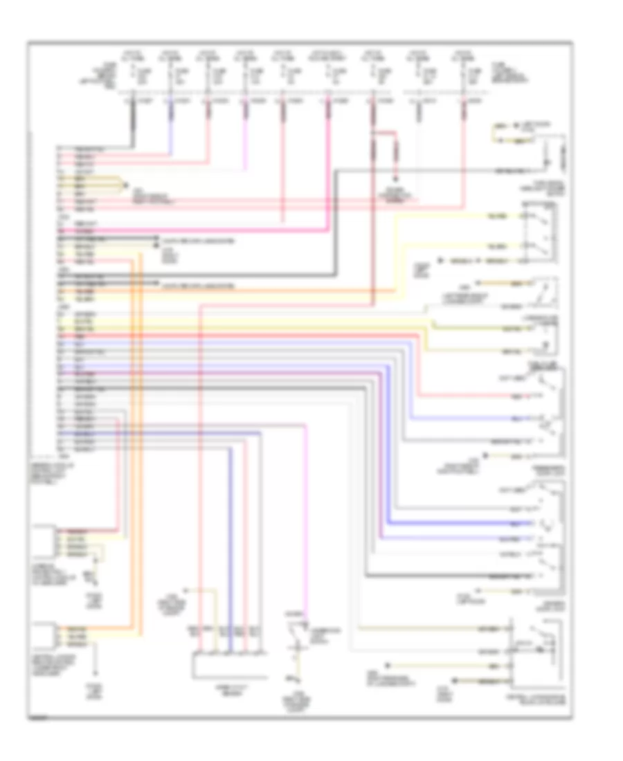
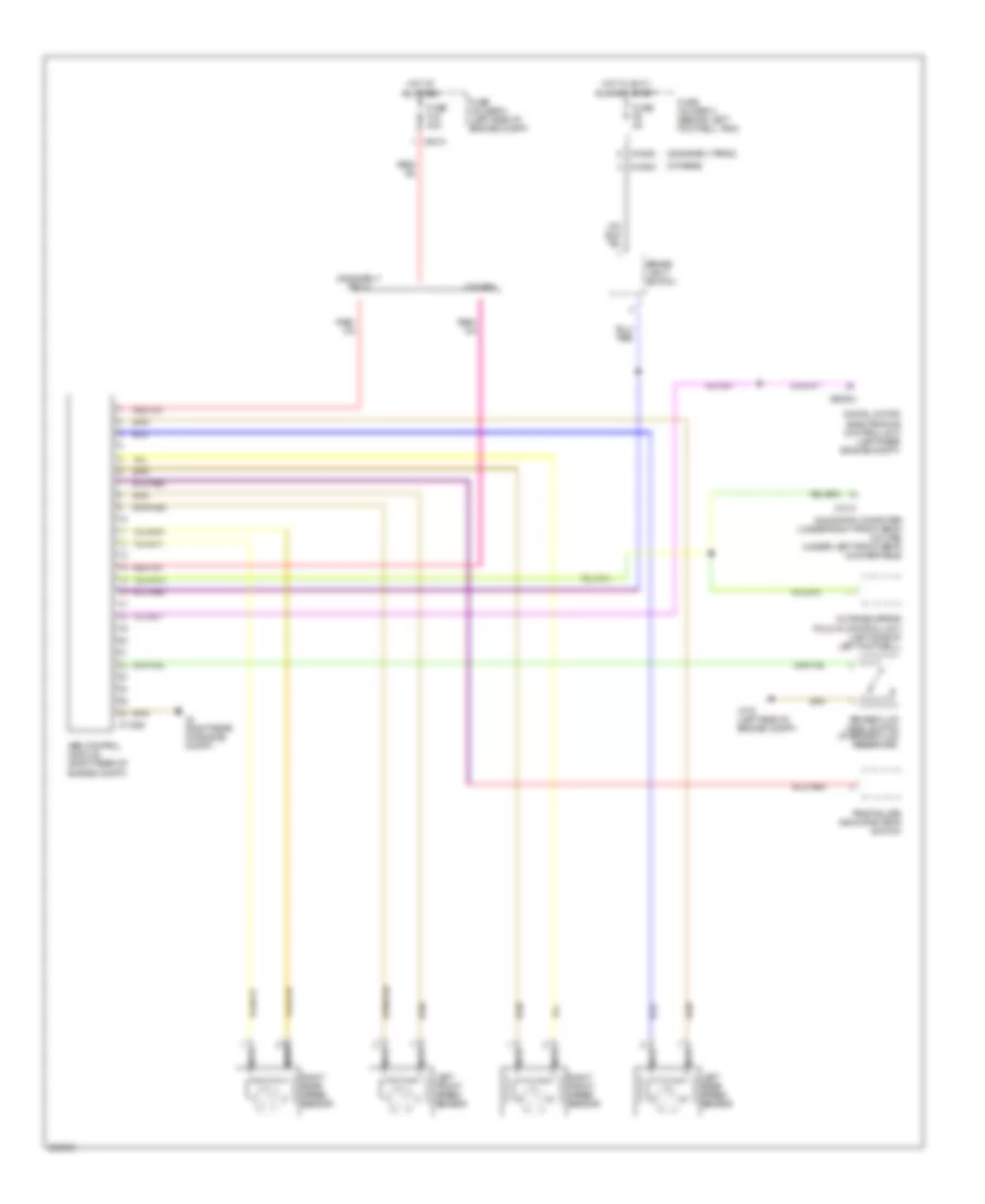
Автомтическая коробка Передач (АКПП) Полная привод (4WD) Блокировка Дифференциала
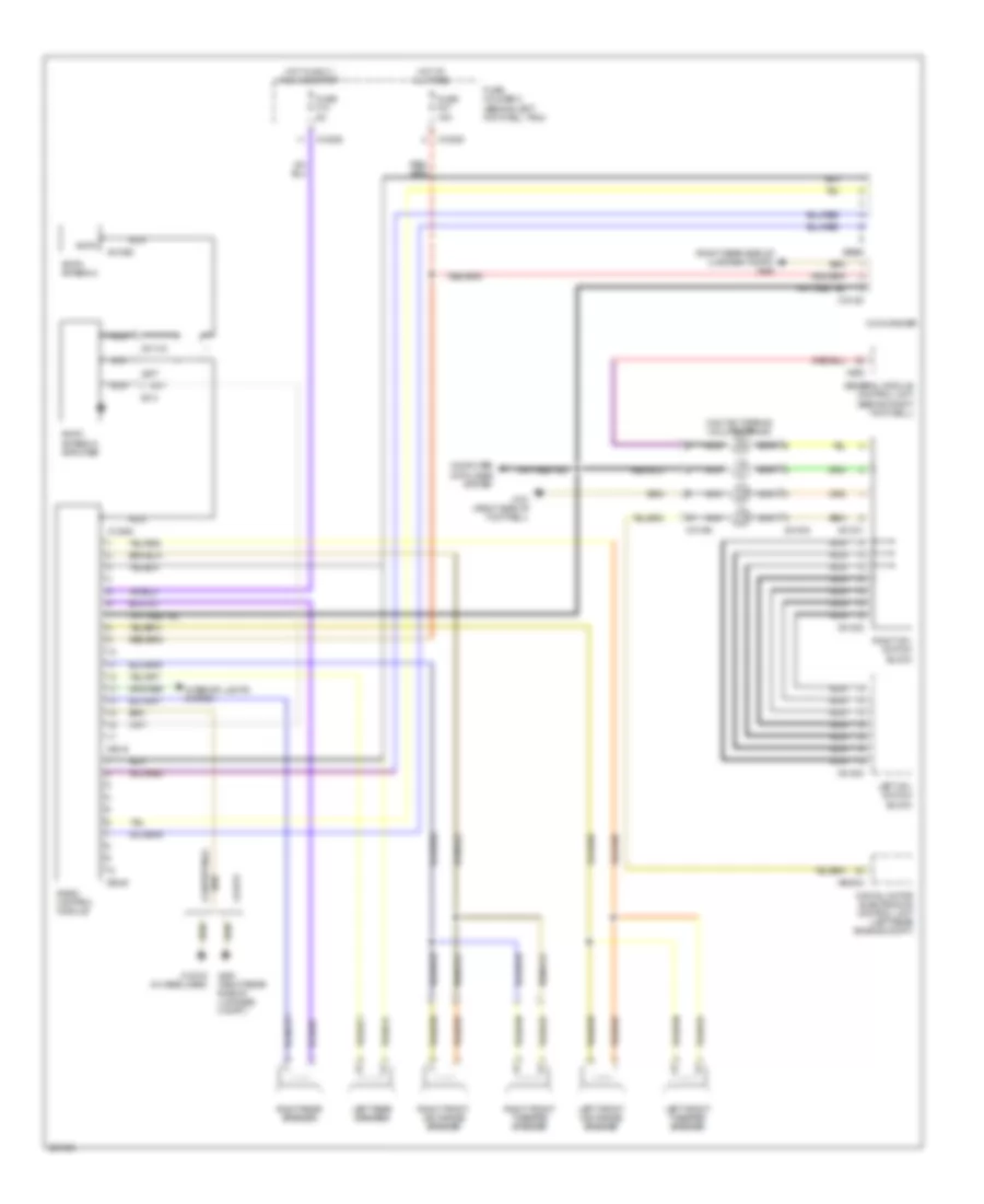
1.6L
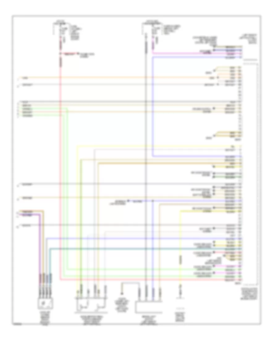
1.6L, Электросхема коробки передач АКПП для MINI Cooper 2007
1.6L, Электросхема коробки передач АКПП для MINI Cooper 2007 - Список элементов:
- (in left door) x1108
- (left side of dash) electronic immobilizer control unit
- Automatic transmission (cvt) switch
- Central shift unit
- Computer data lines system
- Contact spring (volute spring)
- Digital motor electronics control unit (left side of engine compt)
- Exterior lights system
- Fuse f04 15a
- Fuse f13 5a
- Fuse holder 2 (behind left footwell trim)
- Fuse holder 3 (left side of engine compt)
- Gear indicator light
- Hot in on or start
- Hot w/ dme main relay energized
- Interior lights system
- Left button pad
- Nca
- Steering wheel button
- Transmission control unit (left side of left footwell)
- Transmission valve unit
- X01003
- X10195
- X10206
- X1108 (in left door)
- X151 (right side of right footwell)
- X19561
- X4009
- X6000
- X8687
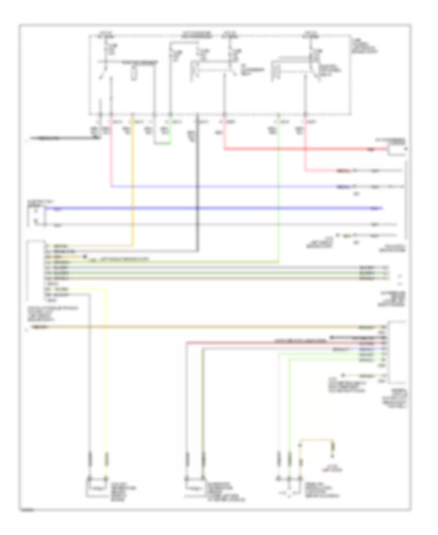
1.6L ТУРБО
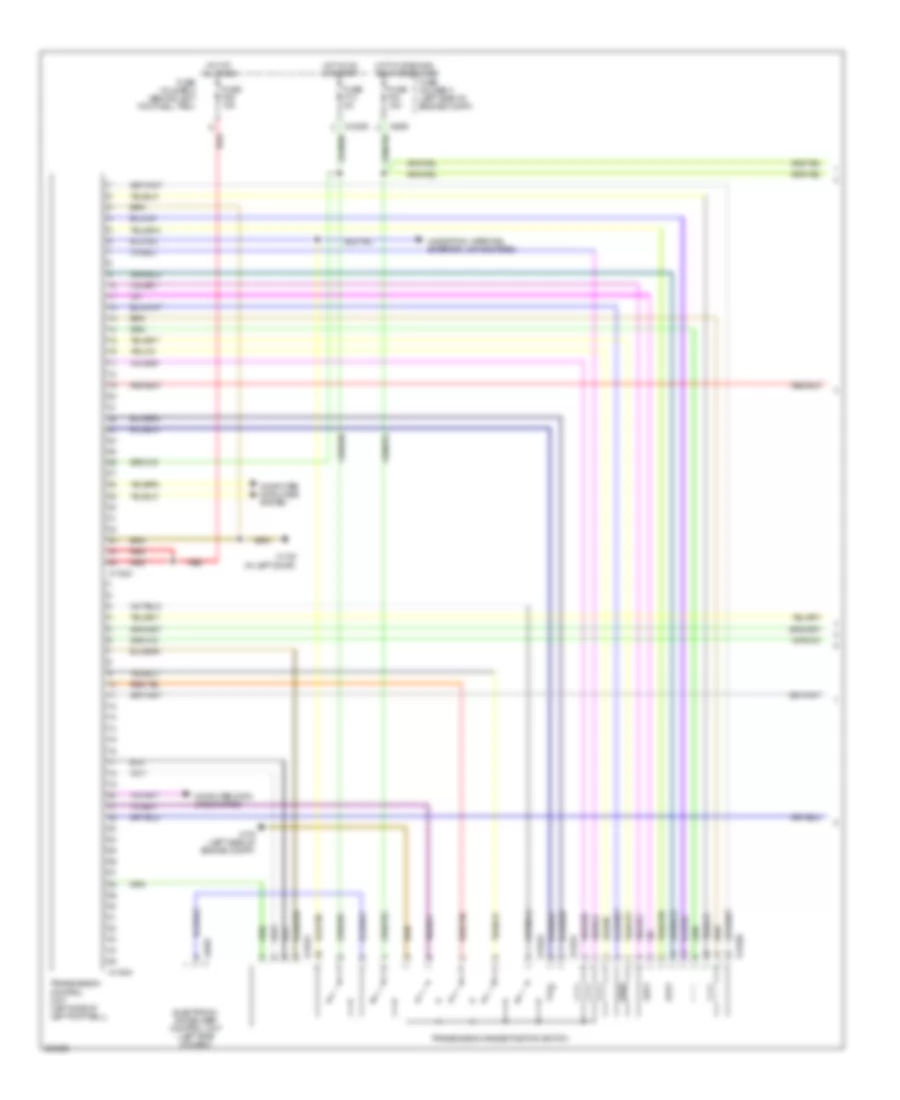
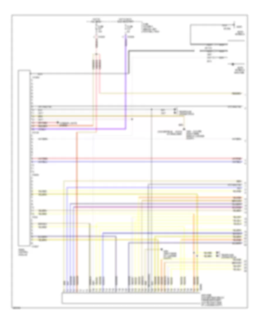
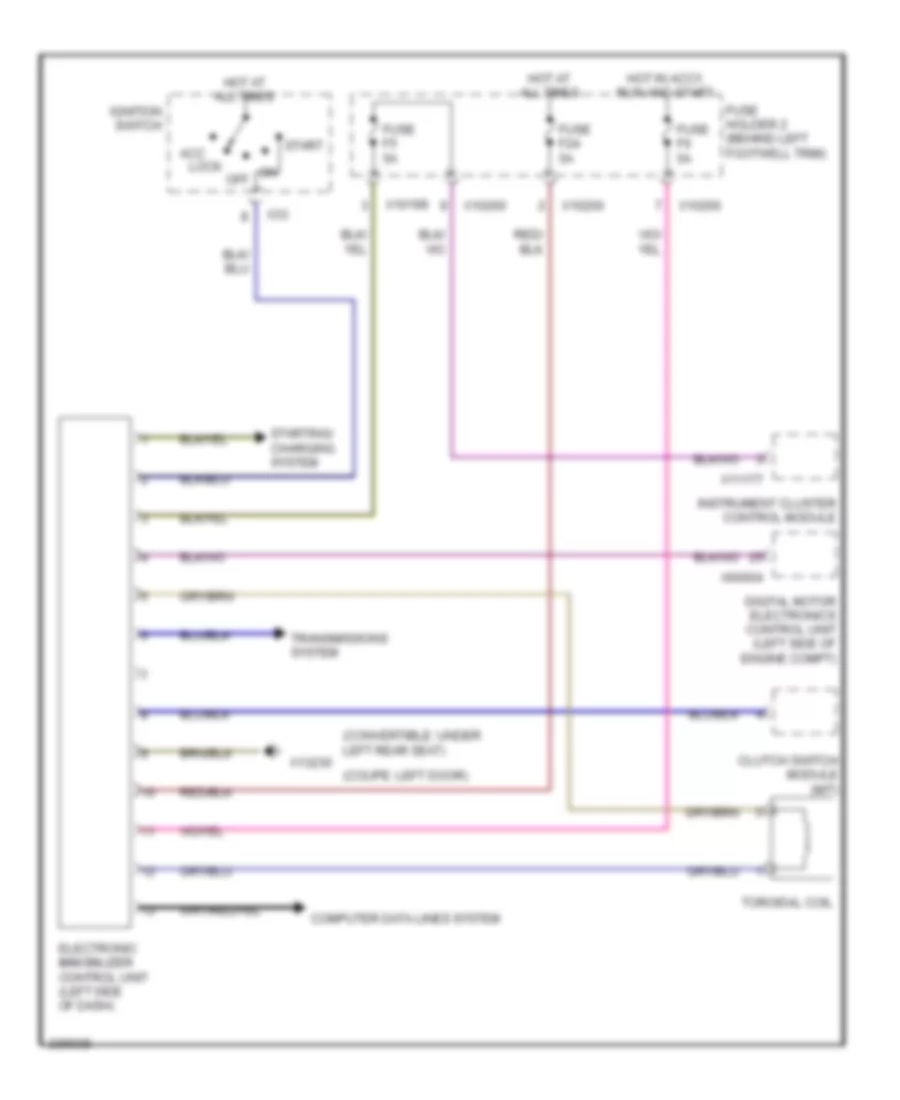
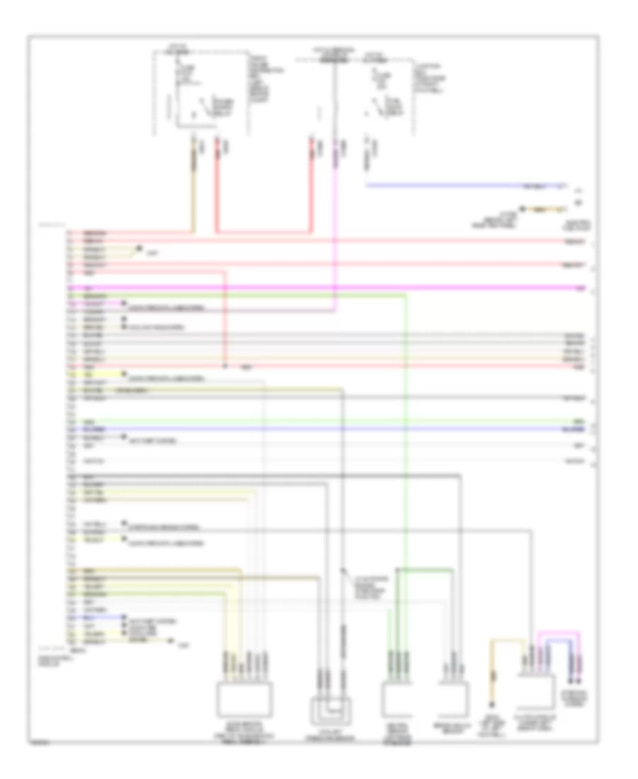
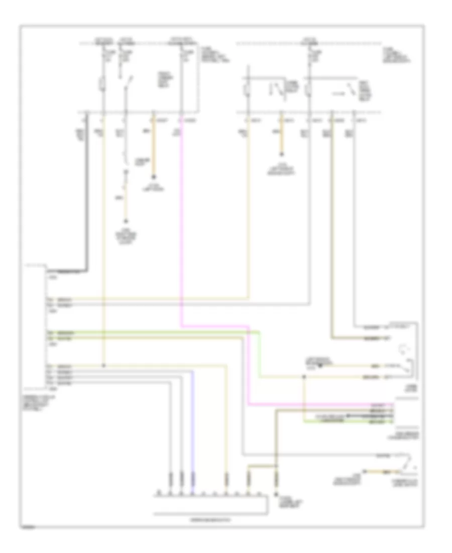
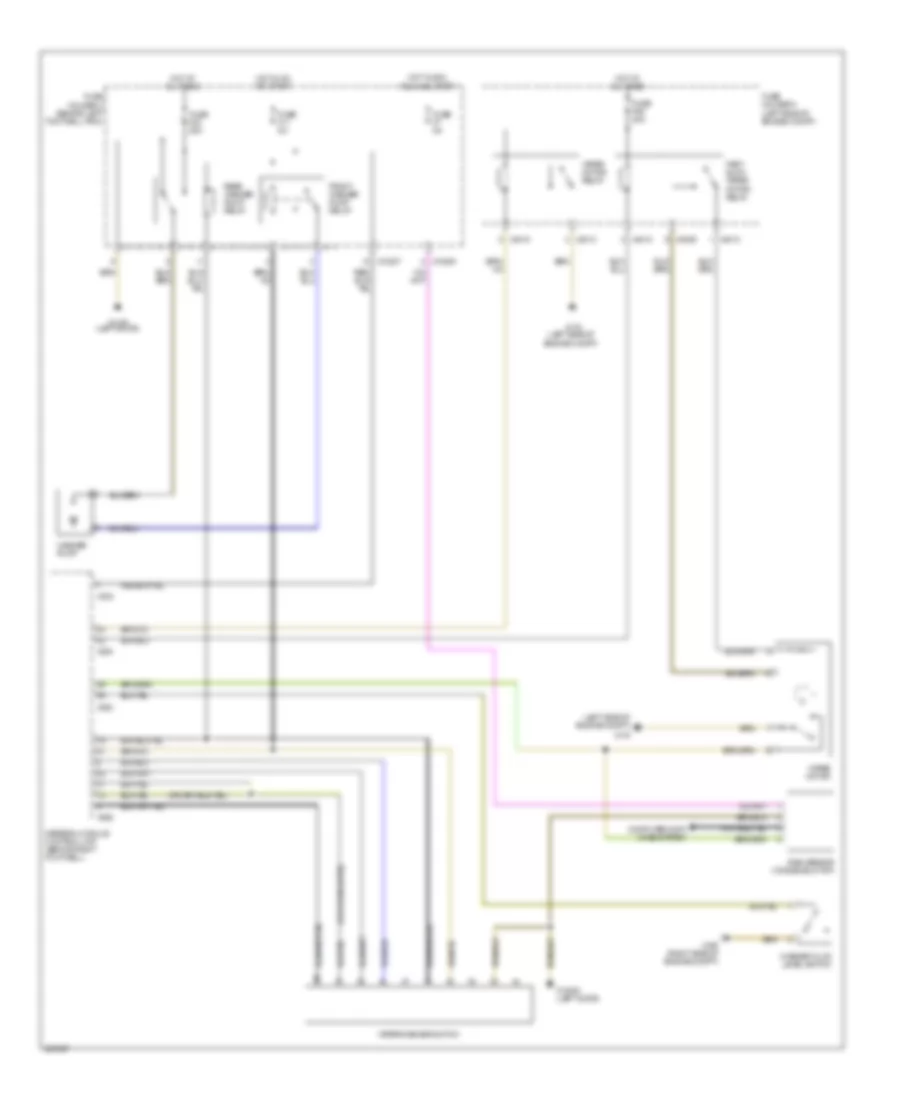
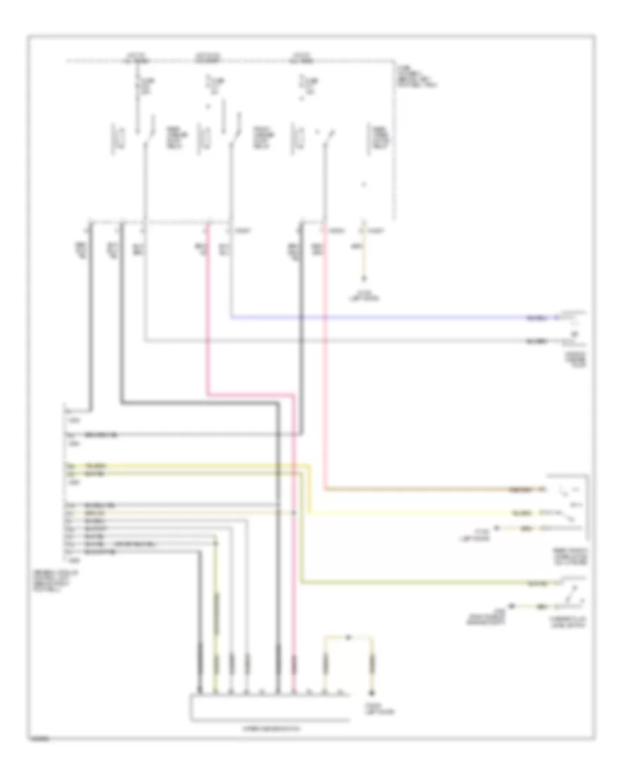
1.6L турбо, Электросхема коробки передач АКПП (1 из 2) для MINI Cooper 2007
1.6L турбо, Электросхема коробки передач АКПП (1 из 2) для MINI Cooper 2007 - Список элементов:
- Computer data lines system
- Electronic immobilizer control unit (left side of dash)
- Fuse f04 15a
- Fuse f13 5a
- Fuse f29 15a
- Fuse holder 2 (behind left footwell trim)
- Fuse holder 3 (left side of engine compt)
- Hot at all times
- Hot in on or start
- Hot w/ dme main relay energized
- Navigation, mirrors, exterior lights system
- Red
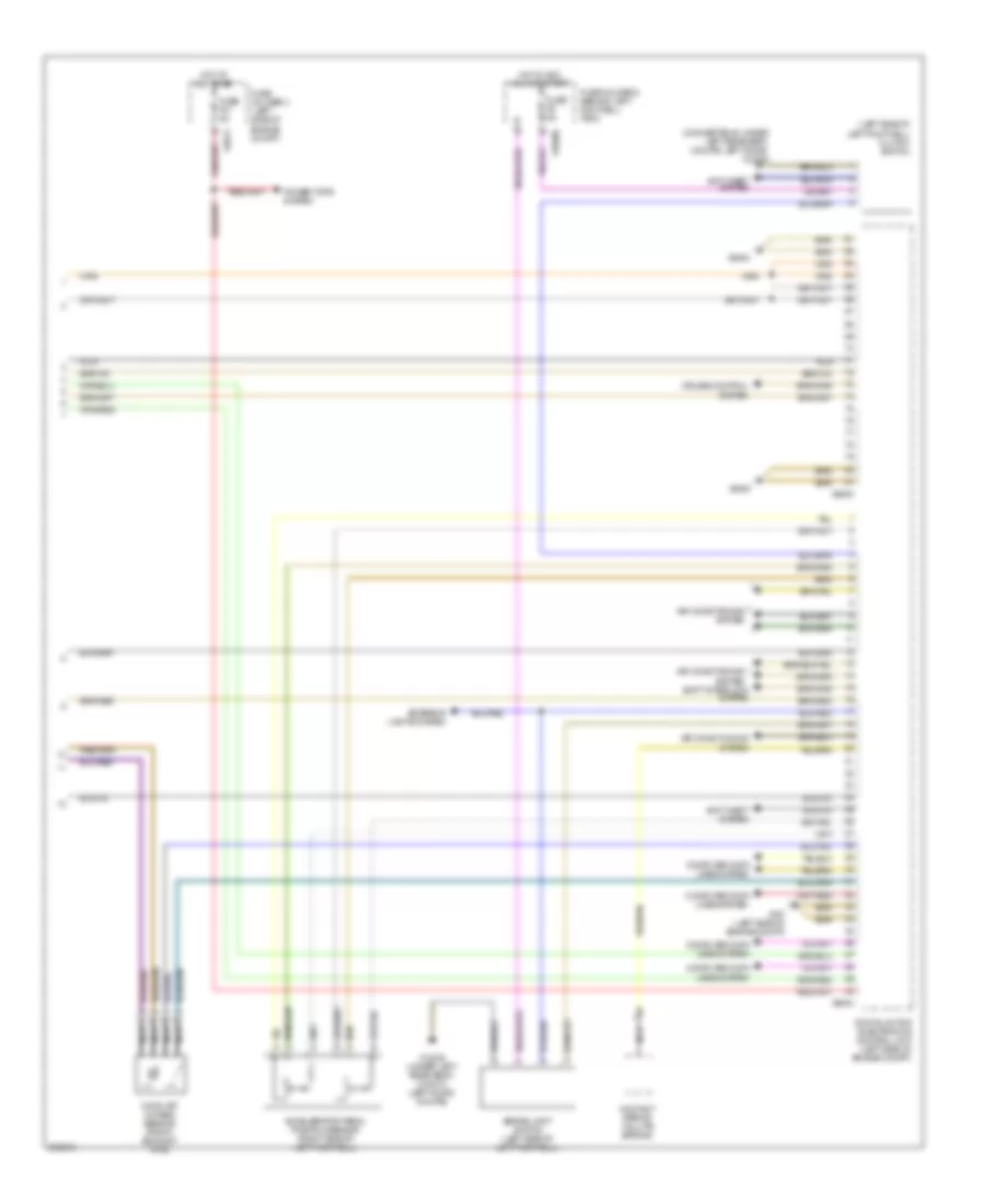
- Transmission control unit (left side of left footwell)
- Transmission range position switch
- X10206
- X1108 (in left door)
- X11630
- X11631
- X11632
- X11633
- X11634
- X1659
- X175 (left side of engine compt)
- X4009
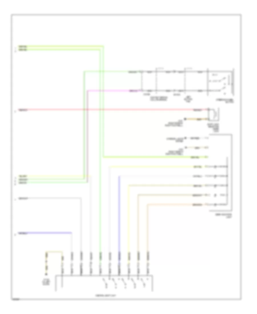
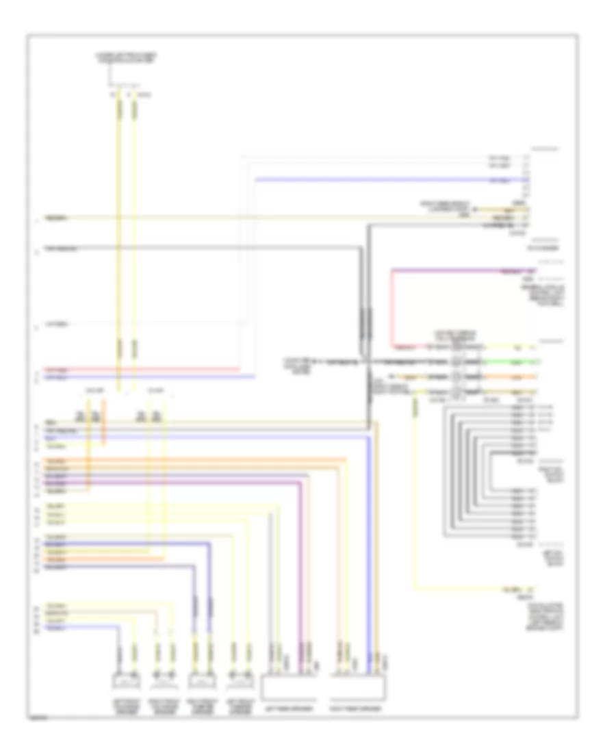
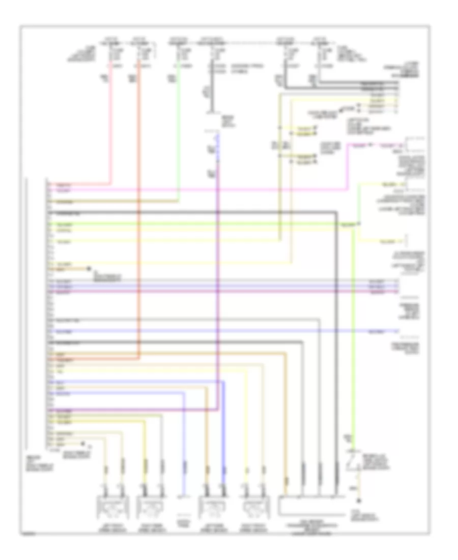
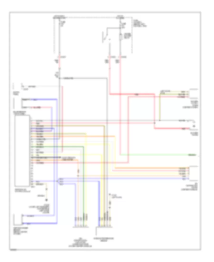
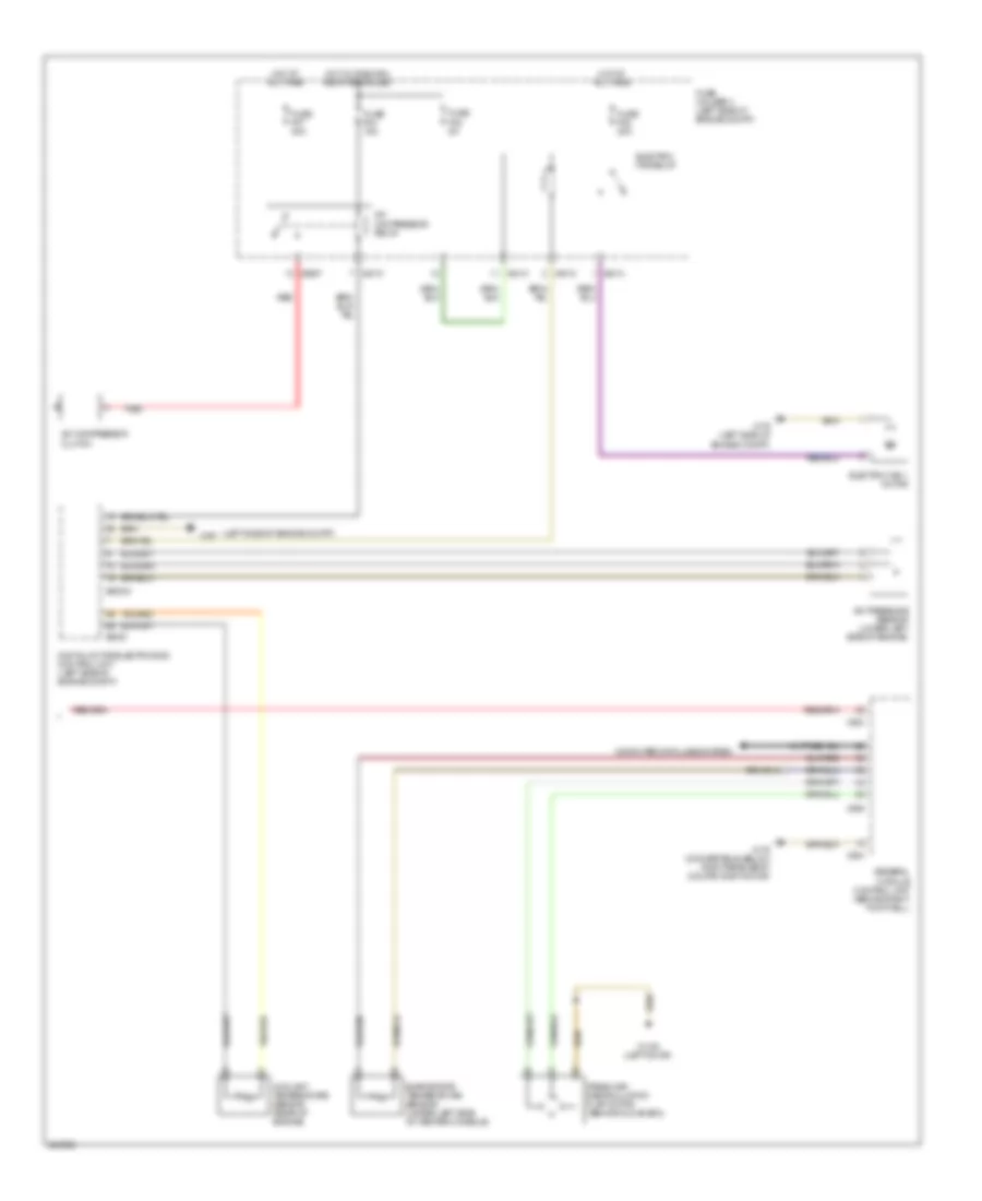
1.6L турбо, Электросхема коробки передач АКПП (2 из 2) для MINI Cooper 2007
1.6L турбо, Электросхема коробки передач АКПП (2 из 2) для MINI Cooper 2007 - Список элементов:
- Central shift unit
- Contact spring (volute spring)
- Gear indicator light
- Interior lights system
- Left button pad
- Nca
- Shift lock selector lever lock
- Steering wheel button
- X01003
- X10195
- X1108 (in left door)
- X151 (right side of right footwell)
БАГАЖНИК ЗАДНЯЯ ДВЕРЬ ЛЮЧОК ТОПЛИВНОГО БАКА
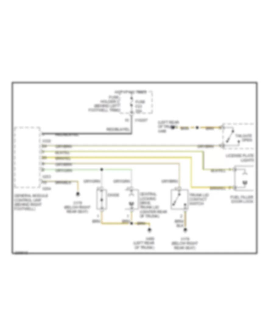
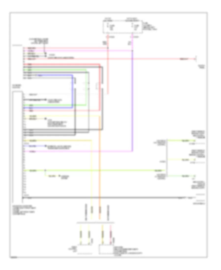
Электросхема открывания багажника и лючка топливного бака, Кабриолет для MINI Cooper 2007
Электросхема открывания багажника и лючка топливного бака, Кабриолет для MINI Cooper 2007 - Список элементов:
- (left rear of trunk) x490
- Central locking drive, trunk lid (center rear of trunk)
- Diode
- Fuel filler door lock
- Fuse f23 20a
- Fuse holder 2 (behind left footwell trim)
- General module control unit (behind right footwell)
- Hot at all times
- License plate lights
- Tailgate open
- Trunk lid contact switch
- X10207
- X179 (below right rear seat)
- X253
- X254
- X332
- X490 (left rear of trunk)
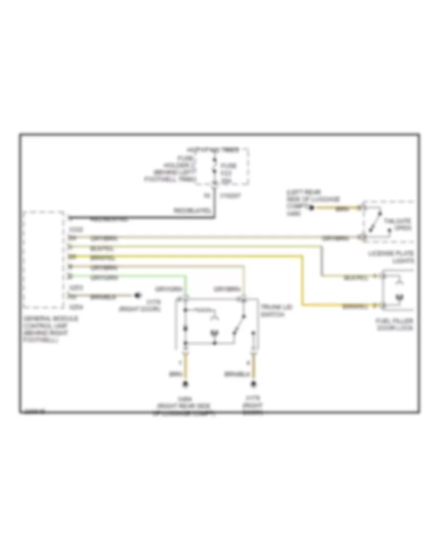
Электросхема открывания багажника и лючка топливного бака, Кабриолет Except для MINI Cooper 2007
Электросхема открывания багажника и лючка топливного бака, Кабриолет Except для MINI Cooper 2007 - Список элементов:
- (left rear side of luggage compt) x490
- Fuel filler door lock
- Fuse f23 20a
- Fuse holder 2 (behind left footwell trim)
- General module control unit (behind right footwell)
- Hot at all times
- License plate lights
- Tailgate open
- Trunk lid switch
- X10207
- X179 (right door)
- X253
- X254
- X332
- X494 (right rear side of luggage compt)
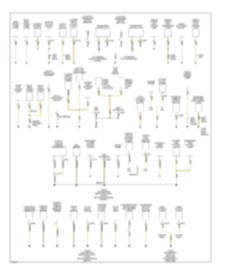
БЛОК ПРЕДОХРАНИТЕЛЕЙ И РЕЛЕ
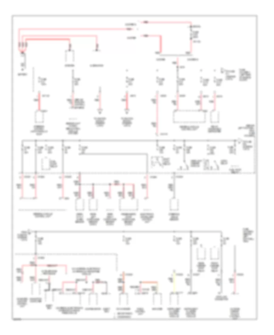
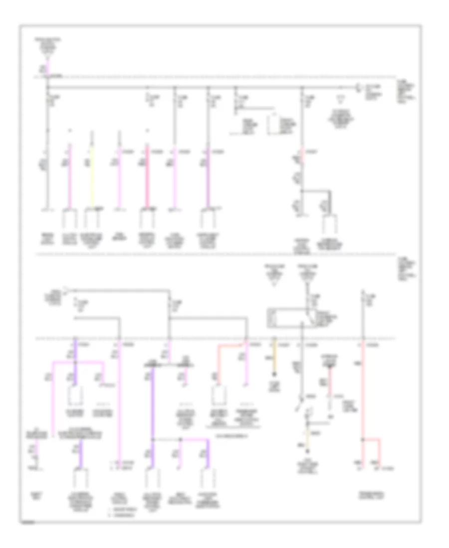
Электросхема блока предохранителей и реле (1 из 5) для MINI Cooper 2007
Электросхема блока предохранителей и реле (1 из 5) для MINI Cooper 2007 - Список элементов:
- (behind left footwell trim) fuse holder 2
- (boost radio)
- (others)
- (wave radio)
- Abs/dsc unit (w dsc) abs control module (w/o dsc)
- Alternator
- Amplifier
- Battery
- Cd changer
- Compensator
- Cooper
- Cooper s
- Data link connector
- Eject box
- Electronic immobilizer control unit
- From d fuse f20 (diagram 1 of 5)
- Front washer pump relay
- Fuel pump relay
- Fuel pump relay 1
- Fuse f1 30a
- Fuse f100 250a
- Fuse f19 30a
- Fuse f2 5a
- Fuse f20 20a
- Fuse f21 10a
- Fuse f22 15a
- Fuse f23 20a
- Fuse f24 5a
- Fuse f25 30a
- Fuse f26 10a
- Fuse f27 15a
- Fuse f28 15a
- Fuse f3 5a
- Fuse f37 20a
- Fuse f4 5a
- Fuse fl10 50a
- Fuse fl12 50a
- Fuse fl2 50a
- Fuse fl4 100a
- Fuse fl6 40a
- Fuse fl7 50a
- Fuse fl8 50a
- Fuse holder 2 (behind left footwell trim)
- Fuse holder 3 (left side of engine compt)
- General module control unit
- Headlight washer module
- Horn relay
- Instrument cluster control module
- Navigation computer
- Nca
- On-board monitor control unit
- Outside mirror fold-in control unit
- Passenger's door microwave sensor (conv)
- Radio control unit
- Rear left microwave sensor (conv)
- Rear right microwave sensor (conv)
- Rear washer pump relay
- Red
- Relay, windshield defroster
- Shift lock relay
- Siren w/ tilt alarm sensor
- Starter
- Steering angle sensor
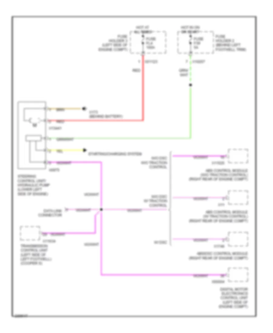
- Steering control unit/hydraulic pump
- To fuse f22 (diagram 1 of 5)
- To fuse fl1 (diagram 2 of 5)
- To ignition switch (diagram 4 of 5)
- Traction control)
- Universal electronics charging & hands- free module
- W/ telephone provisions
- W/ universal electronic charging & hands-free module
- X01121
- X01122
- X01123
- X10178
- X10200
- X10201
- X10202
- X10205
- X10207
- X11177
- X13441
- X14133
- X18126
- X2519
- X254
- X332
- X4008
- X4009
- X4010
- X4015
- X819
Электросхема блока предохранителей и реле (2 из 5) для MINI Cooper 2007
Электросхема блока предохранителей и реле (2 из 5) для MINI Cooper 2007 - Список элементов:
- A/c compressor relay
- Abs w/ traction
- Abs w/o traction
- Abs/dsc unit
- Abs/dsc unit (w dsc) abs control module (w/o dsc)
- Control
- Convertible
- Convertible soft top control module
- Coupe
- Digital motor electronics control unit
- Electric fan relay
- Electric fan stage 2 relay
- Fast/ slow wiper motor relay
- From a fuse fl12 (diagram 1 of 5)
- From e fuse fl11 (diagram 2 of 5)
- Front fog light relay
- Fuse f01 5a
- Fuse f010 15a
- Fuse f06 30a
- Fuse f07 30a
- Fuse f08 30a
- Fuse f09 20a
- Fuse f14 10a
- Fuse f15 20a
- Fuse f16 30a
- Fuse f17 15a
- Fuse f31 30a
- Fuse fl1 50a
- Fuse fl11 50a
- Fuse fl3 40a (convertible)
- Fuse fl5 50a
- Fuse fl9 50a
- Fuse holder 2 (behind left footwell trim)
- Fuse holder 3 (left side of engine compt)
- General module control unit
- Heater blower relay
- On/off wiper motor relay
- Rear defogger relay
- Rear window wiper motor relay
- Red
- Relay 1 for lock & sliding canvas sunroof
- Relay 2 for lock & sliding canvas sunroof
- Relay, convertible top 1
- Relay, convertible top 2
- Sunroof module control unit
- Switching unit, 2-stage blower
- To dme relay (diagram 3 of 5)
- To fuse f01 (diagram 2 of 5)
- To fuse f32 (diagram 5 of 5)
- X10178
- X10199
- X10206
- X11
- X11525
- X13037
- X1746
- X332
- X4007
- X4008
- X4013
- X4015
- X53
- X60004
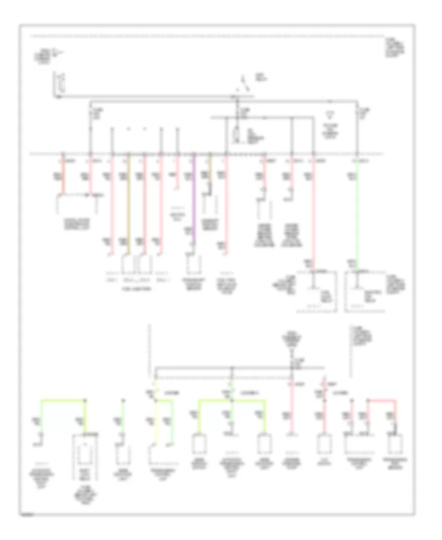
Электросхема блока предохранителей и реле (3 из 5) для MINI Cooper 2007
Электросхема блока предохранителей и реле (3 из 5) для MINI Cooper 2007 - Список элементов:
- (diagram 2 of 5 )
- A/c com- pressor relay
- Automatic transmission central shift unit
- Camshaft position sensor
- Cooper
- Cooper s
- Crankshaft position sensor
- Cvt switch
- Cyl 1
- Cyl 2
- Cyl 3
- Cyl 4
- Digital motor electronics control unit
- Dme relay
- Electric fan relay
- From dme relay (diagram 3 of 5)
- From fuse f09 g
- Fuel injectors
- Fuel pump relay
- Fuel tank vent valve solenoid valve
- Fuse f02 20a
- Fuse f03 15a
- Fuse f04 15a
- Fuse f05 5a
- Fuse holder 2 (behind left footwell trim)
- Fuse holder 3 (left side of engine compt)
- Gear indicator light
- Gear position switch
- Heated oxygen sensor after catalytic converter
- Heated oxygen sensor before catalytic converter
- Ignition coil
- Leakage diagnosis pump
- Nca
- Red
- Shift- lock relay
- To fuse f04 (diagram 3 of 5)
- Transmission control unit
- Transmission rpm sensor
- X10204
- X10205
- X4009
- X4013
- X60004
- X8687
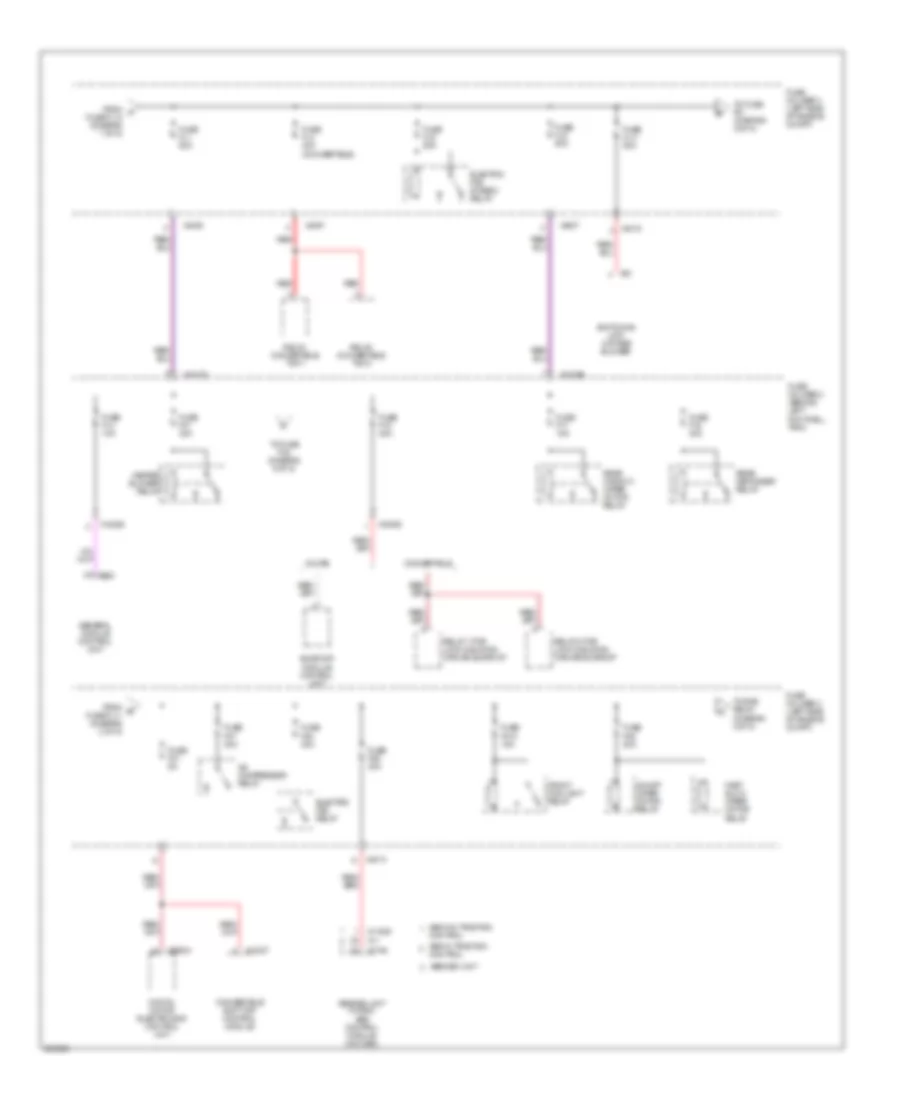
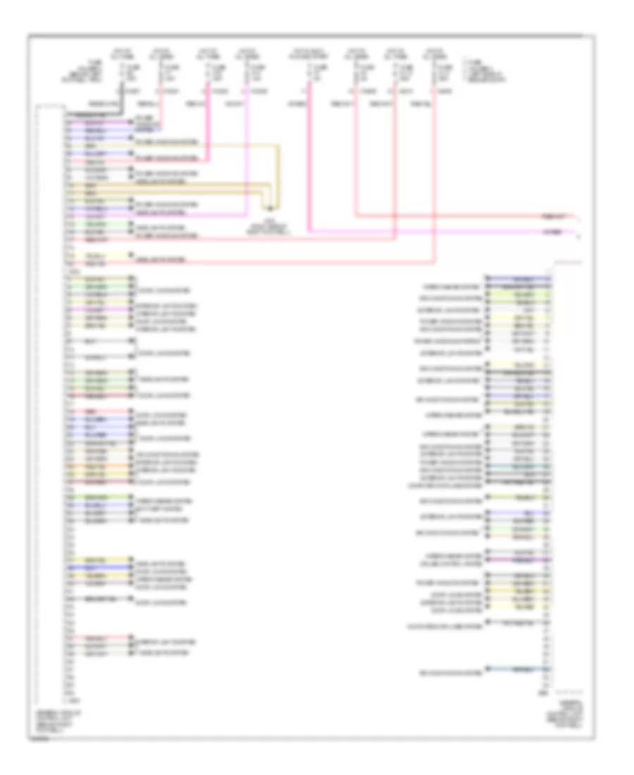
Электросхема блока предохранителей и реле (4 из 5) для MINI Cooper 2007
Электросхема блока предохранителей и реле (4 из 5) для MINI Cooper 2007 - Список элементов:
- (cooper s & bosch)
- (valeo & denso)
- A/t
- Abs w/ traction
- Abs w/o traction
- Abs/dsc unit (w dsc) abs control module (w/o dsc)
- Acc
- Control
- Control, w/ dsc
- Cooper s
- Cvt switch
- Data link connector
- Digital motor electronics control unit
- Driver outside mirror
- Driver's seat heating switch
- Electro- chromic rear view mirror
- Electronic immobilizer control unit
- From fuse f12 (diagram 4 of 5)
- From fuse fl7 (diagram 1 of 5)
- From k fuse f36 (diagram 4 of 5)
- Fuse f12 20a
- Fuse f13 5a (cooper s)
- Fuse f13 5a (cooper)
- Fuse f33 10a
- Fuse f34 10a
- Fuse f35 5a
- Fuse f36 5a
- Fuse f38 10a
- Fuse f40 5a
- Fuse f41 5a
- Fuse holder 2 (behind left footwell trim)
- Gear position switch
- Generator
- Headlight washer module
- Ignition switch
- Instrument cluster control module
- Left windshield washer jet heater
- M/t
- Mirror adjustment switch
- Nca
- Off
- Park distance control unit
- Passenger outside mirror
- Passenger's seat heating switch
- Red
- Reversing light switch
- Right windshield washer jet heater
- Run
- Start
- Steering angle sensor
- Steering control module fan relay
- Steering control unit/hydraulic pump
- Switch panel
- To fuse f39 (diagram 4 of 5)
- To fuse f6 (diagram 5 of 5)
- To ignition switch (diagram 4 of 5)
- Transmission control unit
- W/o mrs system 5
- Windshield defroster relay
- X10178
- X10204
- X10205
- X10206
- X10207
- X11177
- X1659
- X60004
- X6975
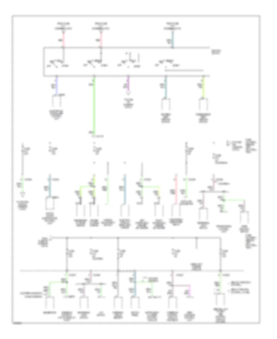
Электросхема блока предохранителей и реле (5 из 5) для MINI Cooper 2007
Электросхема блока предохранителей и реле (5 из 5) для MINI Cooper 2007 - Список элементов:
- Boost radio
- Brake light switch
- Clutch switch module
- Driver's seat belt hall sensor
- Eject box
- Electronic immobilizer control unit
- From fuse f29 (diagram 5 of 5)
- From fuse f31 (diagram 2 of 5)
- From ignition switch (diagram 4 of 5)
- From m fuse f29 (diagram 5 of 5)
- Front cigar lighter
- Front cigarette lighter relay
- Front washer pump relay
- Fuse f10 5a
- Fuse f11 5a
- Fuse f18 5a
- Fuse f29 15a
- Fuse f30 5a
- Fuse f32 15a
- Fuse f6 5a
- Fuse f7 5a
- Fuse f8 5a
- Fuse f9 5a
- Fuse holder 2 (behind left footwell trim)
- General module control unit
- Heating & a/c control module
- Indicator lamp, passenger deactivation
- Instrument cluster control module
- Interior lights system
- Interior temperature/ fan sensor
- Mrs system 5
- Multiple restraint system control unit
- Navigation computer
- Nca
- On-board monitor
- Passenger air bag deactivation switch
- Radio control module
- Rain sensor
- Rear washer pump relay
- Red
- Seat occupancy recognition
- To front cigarette lighter relay (diagram 5 of 5)
- To fuse f10 (diagram 5 of 5)
- Transmission control unit
- Turn indicator/ low beam switch
- Universal electronics charging & hands-free module
- W/ telephone provisions
- W/ universal electronics charging & hands-free module
- W/o mrs system 5
- Wave radio
- X10199
- X10200
- X10201
- X10203
- X10206
- X10207
- X1108 (left door)
- X11177
- X11633
- X1213
- X1313
- X151 (right side of right footwell)
- X1659
- X18126
- X2519
- X254
- X9320
БЛОКИ УПРАВЛЕНИЯ КУЗОВОМ
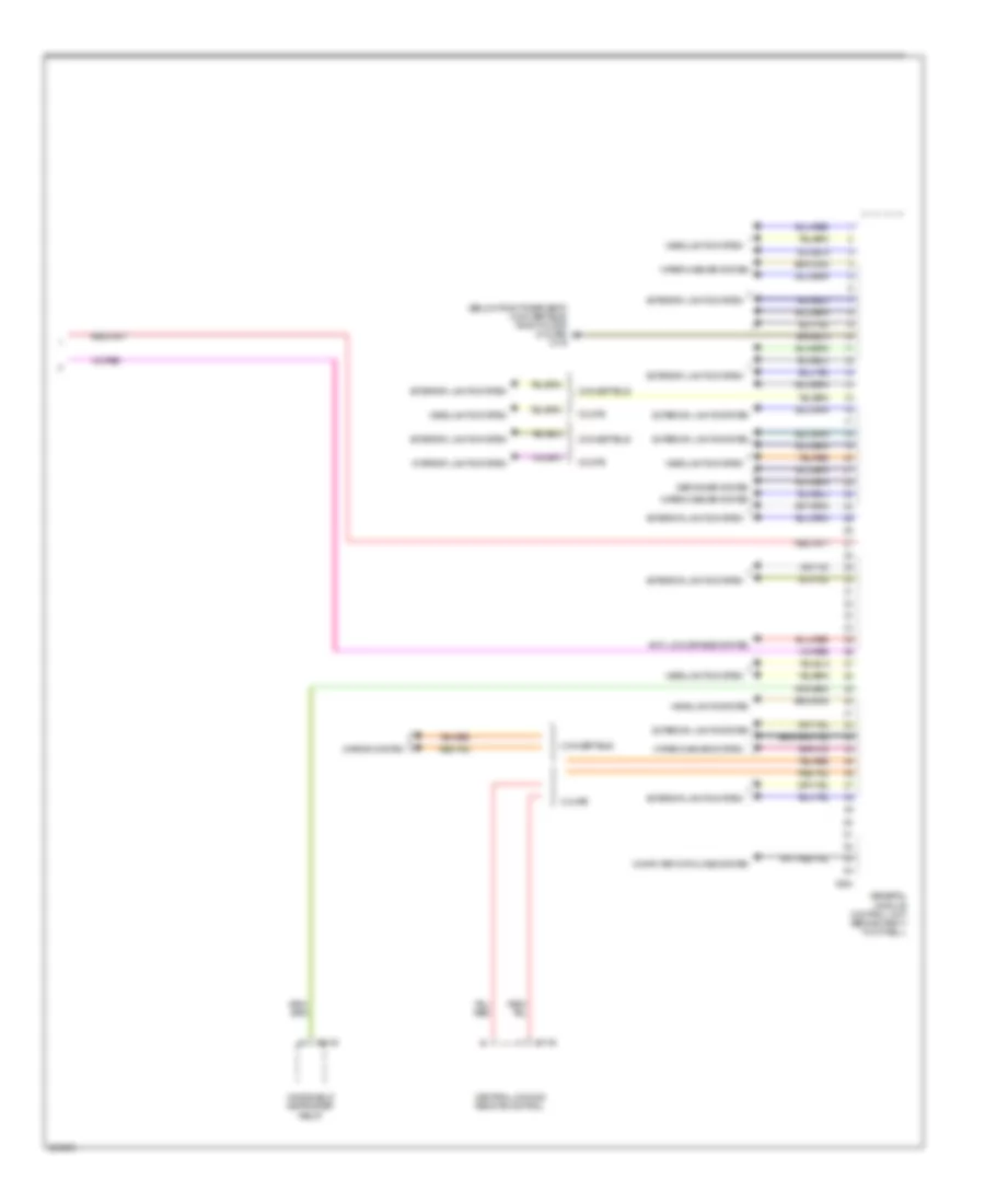
Электросхема блоков управления кузовом (1 из 2) для MINI Cooper 2007
Электросхема блоков управления кузовом (1 из 2) для MINI Cooper 2007 - Список элементов:
- Air conditioning system
- Anti-theft system
- Computer data lines system
- Cruise control system
- Door locks system
- Exterior lights system
- Fuse f1 30a
- Fuse f14 10a
- Fuse f19 30a
- Fuse f4 5a
- Fuse f7 5a
- Fuse fl 12 50a
- Fuse fl 8 50a
- Fuse holder 2 (behind left footwell trim)
- Fuse holder 3 (left side of engine compt)
- Fuse f32 20a
- General module control unit (behind right footwell)
- Headlights system
- Hot at all times
- Hot in accy, run and start
- Interior lights system
- Power windows system
- Power windows systems
- Red
- Wiper/washer system
- X10201
- X10202
- X10206
- X10207
- X151 (right side of right footwell)
- X253
- X255
- X332
- X4009
- X4010
Электросхема блоков управления кузовом (2 из 2) для MINI Cooper 2007
Электросхема блоков управления кузовом (2 из 2) для MINI Cooper 2007 - Список элементов:
- (below right rear seat) (convertible) (right door) (coupe) x179
- Anti-lock brakes system
- Central locking remote control
- Computer data lines system
- Convertible
- Coupe
- Defogger system
- Exterior lights system
- General module control unit (behind right footwell)
- Headlights system
- Interior lights system
- Mirror system
- Windshield defroster relay
- Wiper/washer system
- X1143
- X254
- X3148
БЛОКИРОВКИ СЕЛЕКТОРА СТОЯНОЧНЫЙ ТОРМОЗ
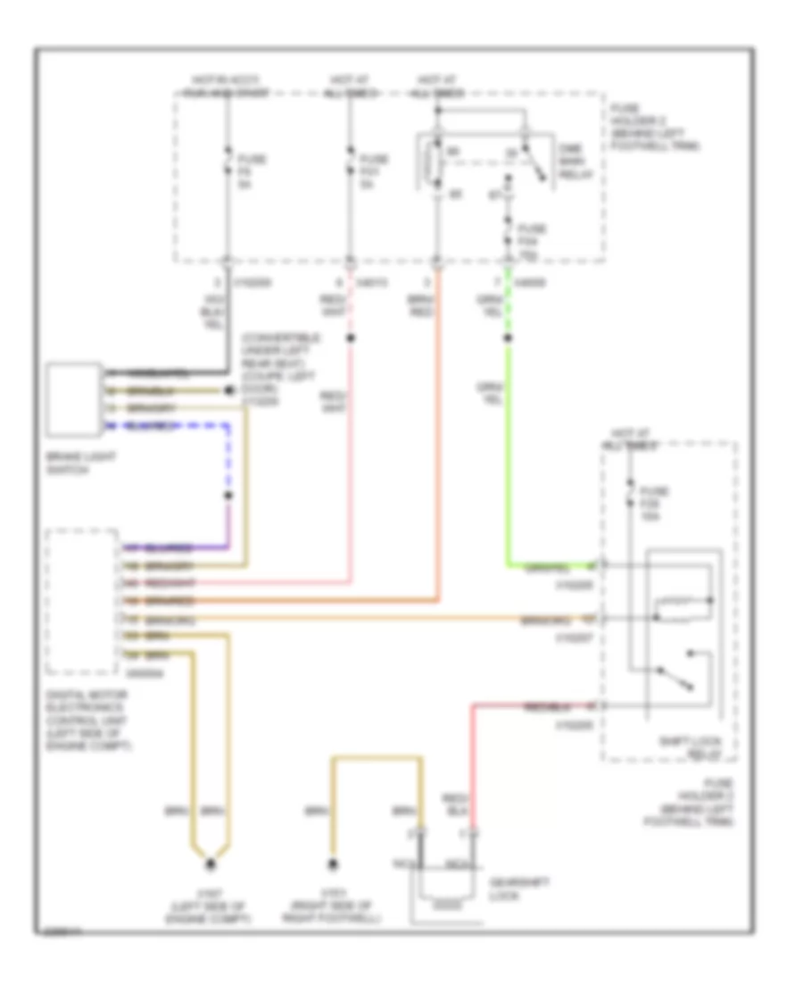
Электросхема блокировки селектора для MINI Cooper 2007
Электросхема блокировки селектора для MINI Cooper 2007 - Список элементов:
- (convertible: under left rear seat) (coupe: left door) x13230
- Brake light switch
- Digital motor electronics control unit (left side of engine compt)
- Dme main relay
- Fuse f01 5a
- Fuse f04 15a
- Fuse f26 10a
- Fuse f6 5a
- Fuse holder 2 (behind left footwell trim)
- Gearshift lock
- Hot at all times
- Hot in accy, run and start
- Nca
- Shift lock relay
- X10200
- X10205
- X10207
- X151 (right side of right footwell)
- X167 (left side of engine compt)
- X4009
- X4013
- X60004
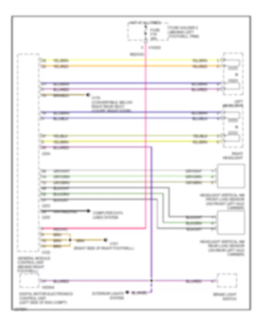
ВНЕШНЕЕ ОСВЕЩЕНИЕ
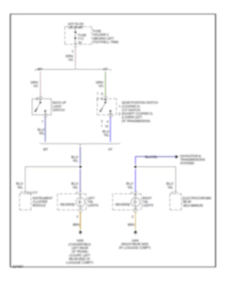
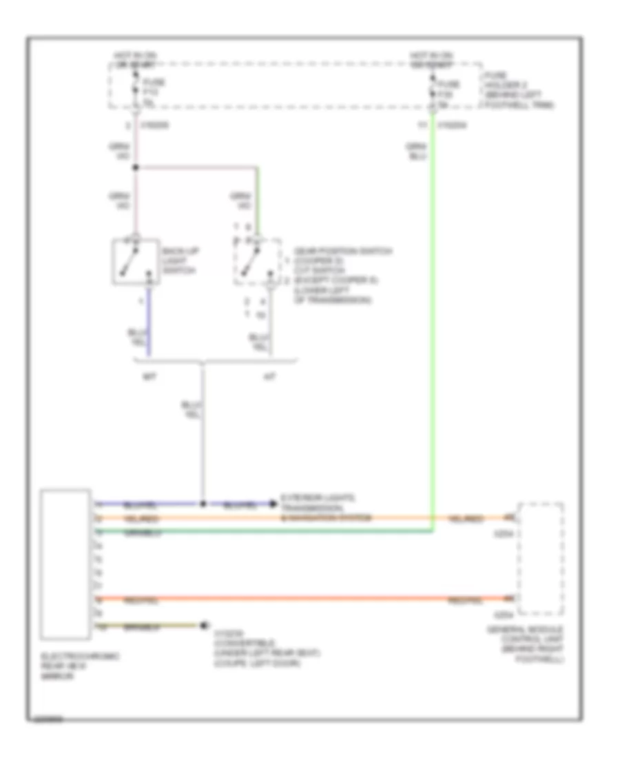
Электросхема заднего хода для MINI Cooper 2007
Электросхема заднего хода для MINI Cooper 2007 - Список элементов:
- (lower left of transmission)
- A/t
- Back-up light switch
- Cvt switch (except cooper s)
- Electrochromic rear view mirror
- Fuse f13 5a
- Fuse holder 2 (behind left footwell trim)
- Gear position switch (cooper s)
- Hot in on or start
- Instrument cluster module
- Left tail lights
- M/t
- Navigation & transmissions systems
- Reverse
- Right tail lights
- X11177
- X490 (convertible: left rear of trunk) (coupe: left rear side of luggage compt)
- X494 (right rear side of luggage compt)
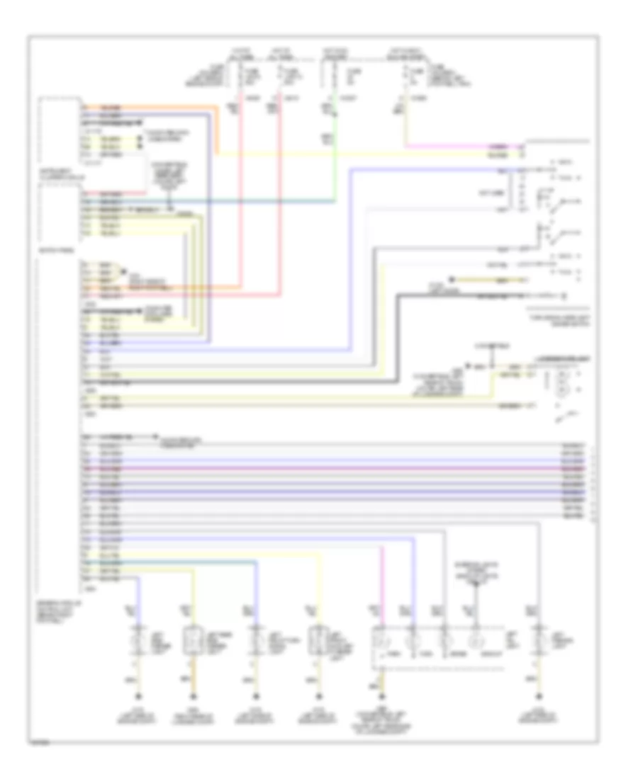
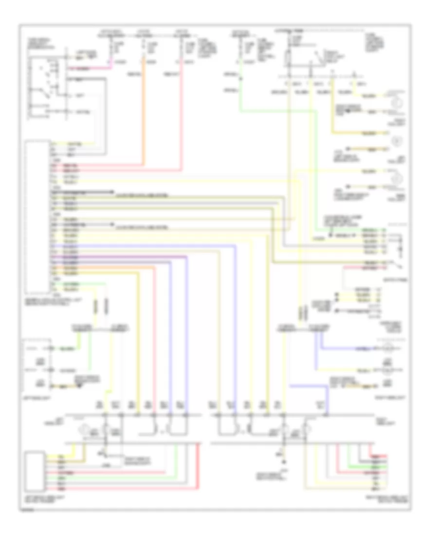
Электросхема внешнего освещения (1 из 2) для MINI Cooper 2007
Электросхема внешнего освещения (1 из 2) для MINI Cooper 2007 - Список элементов:
- (convertible: under left rear seat) (coupe: left door)
- (right rear of luggage compt)
- Backup
- Brake
- Computer data lines system
- Convertible
- Exterior lights system (back-up lights circuit)
- Fuse 5a
- Fuse holder 2 (behind left footwell trim)
- Fuse holder 3 (left side of engine compt)
- Fuse link 12 50a
- Fuse link 8 50a
- General module control unit (behind right footwell)
- Hot at all times
- Hot in accy, run and start
- Hot in on or start
- Instrument cluster module
- Left front auxiliary flasher light
- Left front turn signal light
- Left parking light
- Left rear side marker light
- Left side marker light
- Left tail light
- License plate light
- Not used
- Park
- Switch panel
- Turn
- Turn signal/headlight dimmer switch
- X10200
- X10207
- X1108 (left door)
- X11175
- X11177
- X13230
- X151 (right side of right footwell)
- X175 (left side of engine compt)
- X253
- X254
- X255
- X332
- X4009
- X4010
- X490 (convertible: left rear of trunk coupe: left rear of luggage compt)
- X490 (convertible: left rear of trunk coupe: left rear side of luggage compt)
- X494
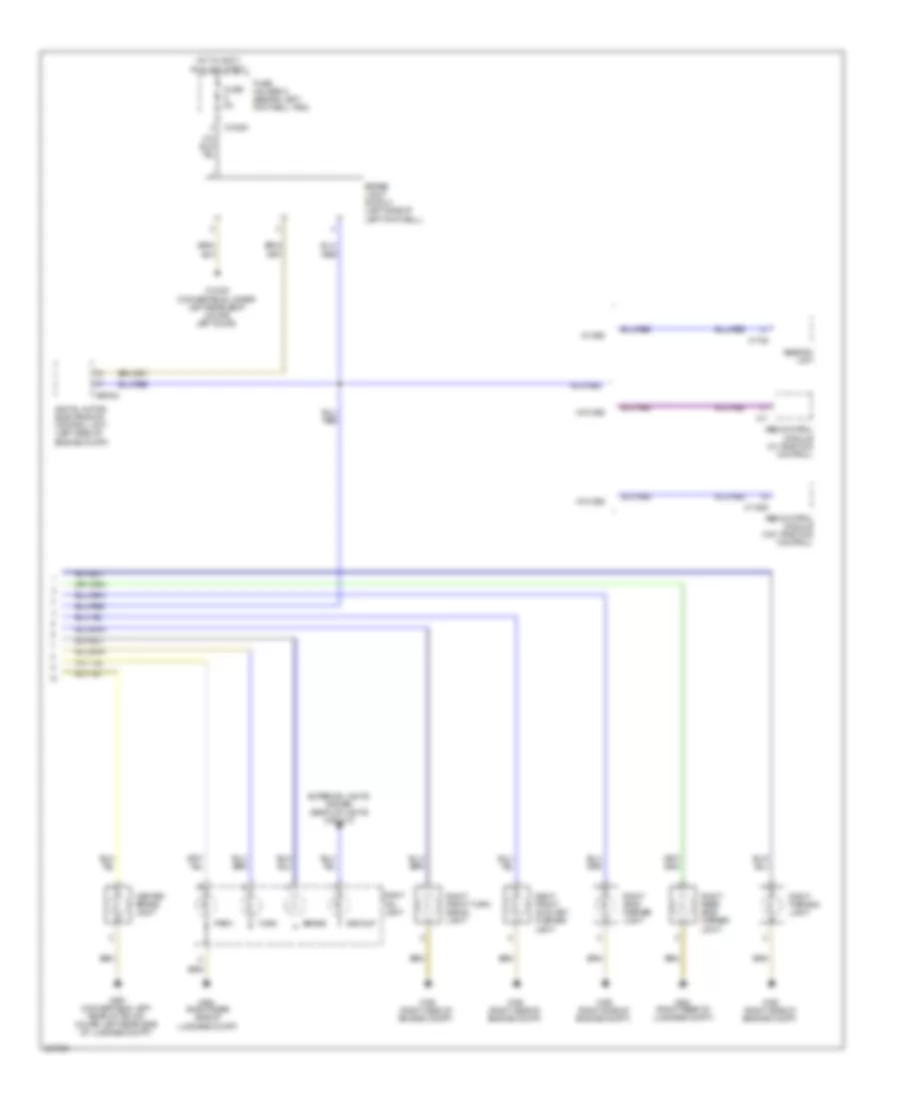
Электросхема внешнего освещения (2 из 2) для MINI Cooper 2007
Электросхема внешнего освещения (2 из 2) для MINI Cooper 2007 - Список элементов:
- Abs control module (w/ traction control)
- Abs control module (w/o traction control)
- Abs/dsc unit
- Backup
- Brake
- Brake light switch (left side of left footwell)
- Center brake light
- Digital motor electronics control unit (left side of engine compt)
- Exterior lights system (back-up lights circuit)
- Fuse 5a
- Fuse holder 2 (behind left footwell trim)
- Hot in accy, run and start
- Park
- Right front auxiliary flasher light
- Right front turn signal light
- Right parking light
- Right rear side marker light
- Right side marker light
- Right tail light
- Turn
- W/ dsc
- W/o dsc
- X10200
- X11
- X11525
- X13230 (convertible: under left rear seat coupe: left door)
- X165 (right side of engine compt)
- X1746
- X490 (convertible: left rear of trunk coupe: left rear side of luggage compt)
- X494 (right rear of luggage compt)
- X494 (right rear side of luggage compt)
- X60004
ВНУТРЕННЕЕ ОСВЕЩЕНИЕ
Электросхема подсветки, Кабриолет для MINI Cooper 2007
Электросхема подсветки, Кабриолет для MINI Cooper 2007 - Список элементов:
- (left door)
- (under left rear seat)
- Auxiliary instrument cluster
- Driver's door entrance light
- Driver's side footwell light
- Front interior/ reading lamp
- Front left door opener light
- Front right door opener light
- Fuse f14 10a
- Fuse f21 10a
- Fuse holder 2 (behind left footwell trim)
- General module control unit (behind right footwell)
- Glove compartment light
- Hot at all times
- Instrument cluster
- Interior light
- Interior light switch
- Interior lights system (illumination circuit)
- Left make-up mirror light
- Left reading light
- Luggage compartment light
- Passenger's door entrance light
- Passenger's side footwell light
- Rear power window switch
- Right make-up mirror light
- Right reading light
- Switch panel
- Top light
- W/ footwell lights
- W/ interior light package
- W/o footwell lights
- W/o interior light package
- X10202
- X10206
- X1108
- X11175
- X11177
- X13230
- X13230 (under left rear seat)
- X151 (right side of right footwell)
- X1740
- X1741
- X253
- X254
- X332
- X490 (left rear of trunk)
- X494 (right rear of luggage compt)
Электросхема подсветки, Кабриолет Except для MINI Cooper 2007
Электросхема подсветки, Кабриолет Except для MINI Cooper 2007 - Список элементов:
- (left door)
- Auxiliary instrument cluster
- Driver's door entrance light
- Front interior/ reading lamp
- Front left door opener light
- Front right door opener light
- Fuse f14 10a
- Fuse f21 10a
- Fuse holder 2 (behind left footwell trim)
- General module control unit (behind right footwell)
- Glove compartment light
- Hot at all times
- Instrument cluster
- Interior light
- Interior light switch
- Interior lights system (illumination circuit)
- Left front footwell light
- Left make-up mirror light
- Left reading light
- Luggage compartment light
- Passenger's door entrance light
- Rear interior/ reading lamp
- Right front footwell light
- Right make-up mirror light
- Right reading light
- Switch panel
- Top- light
- W/ interior light package
- W/o interior light package
- X10202
- X10206
- X1108
- X11175
- X11177
- X13230
- X13230 (left door)
- X151 (right side of right footwell)
- X1740
- X1741
- X179 (right door)
- X253
- X254
- X332
- X490 (left rear of trunk)
- X494 (right rear of luggage compt)
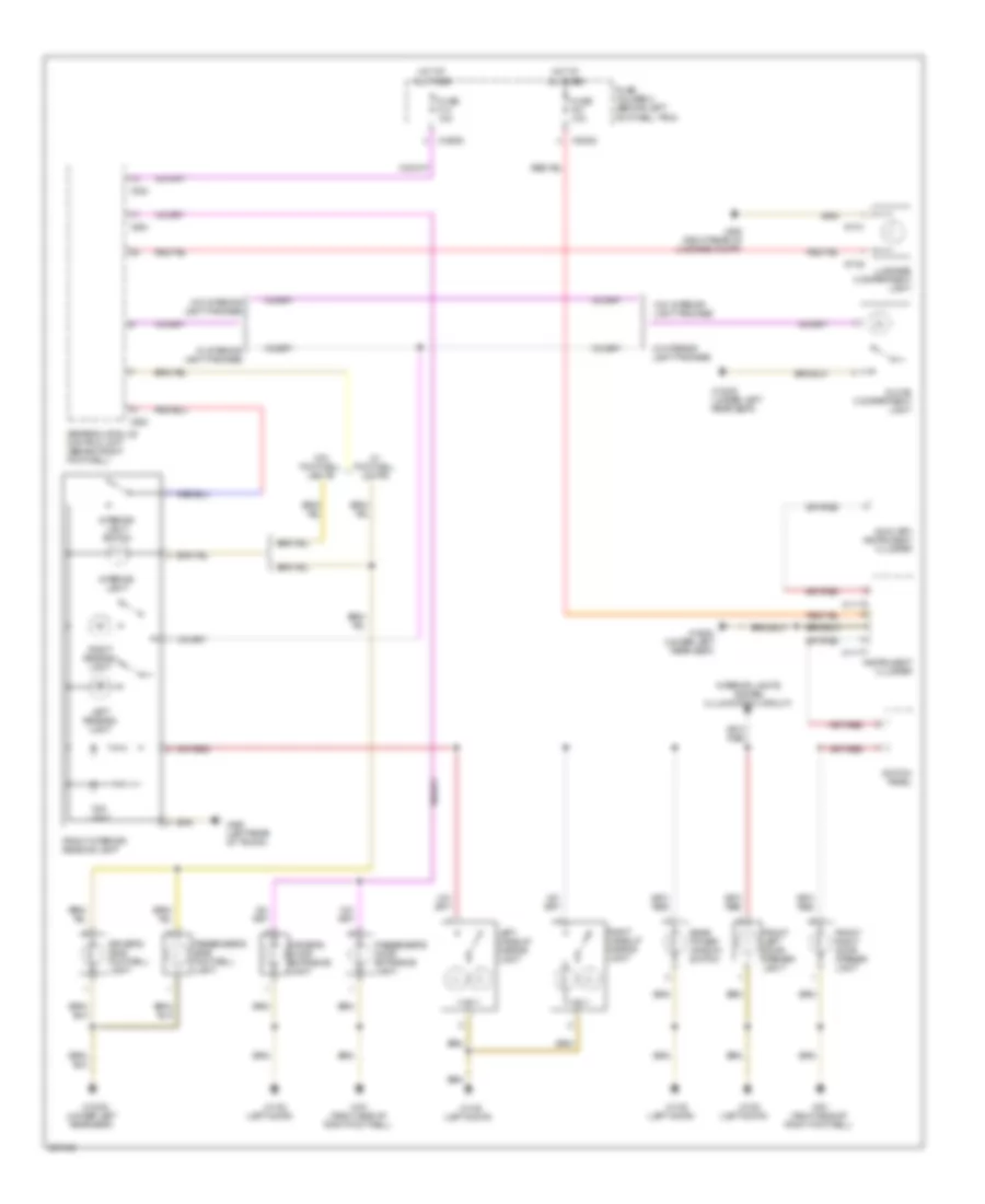
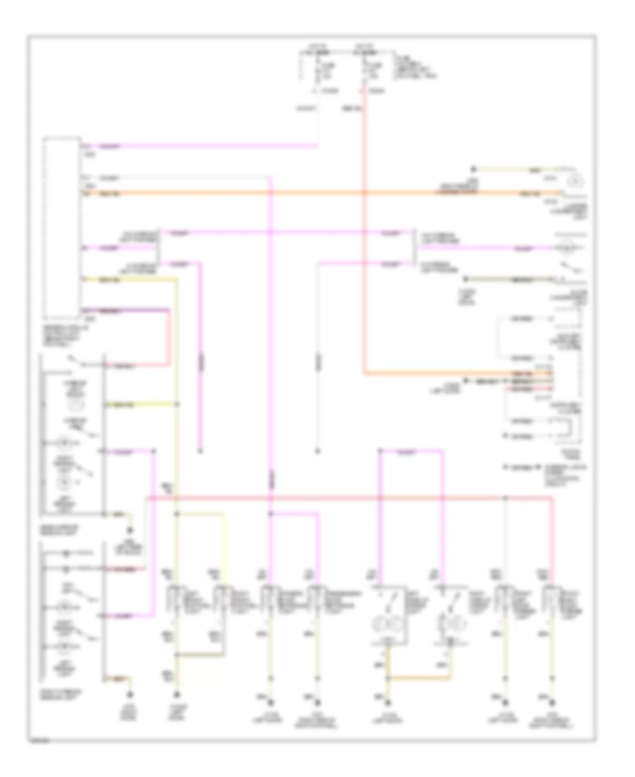
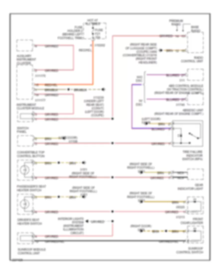
Электросхема подсветки приборов для MINI Cooper 2007
Электросхема подсветки приборов для MINI Cooper 2007 - Список элементов:
- (left door) x1108
- (right door) x179
- (right rear side of luggage compt) (coupe) x494 (convertible) x13016 (right front headliner)
- (right side of right footwell) x151
- Abs control module (w/ traction control) (right rear of engine compt.)
- Abs/dsc unit (right rear of engine compt.)
- Auxiliary instrument cluster
- Base radio
- Convertible top control button
- Driver's seat heater switch
- Front cigar lighter
- Fuse f21 10a
- Fuse holder 2 (behind left footwell trim)
- Gear indicator light
- Hot at all times
- Instrument cluster module
- Interior lights system (instrument illumination circuit)
- Nca
- Passenger's seat heater switch
- Premium radio
- Radio control unit
- Sunroof control switch
- Sunroof module control unit
- Switch panel
- Tire failure indicator switch (rpa)
- W/ dsc
- W/o dsc
- X10202
- X11
- X11175
- X11177
- X1213
- X13230 (under left rear seat) (convt) (left door) (coupe)
- X151 (right side of right footwell)
- X1746
- X9320
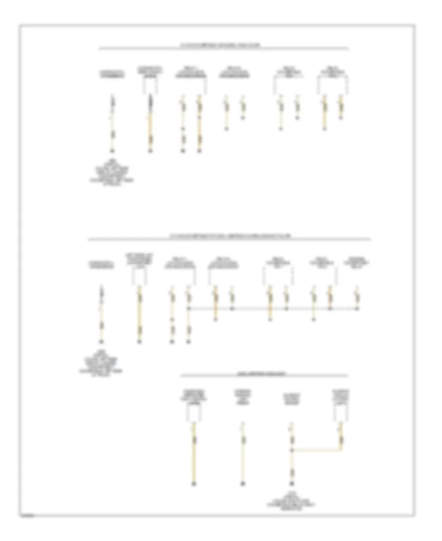
ЗАЗЕМЛЕНИЕ ПОДКЛЮЧЕНИЕ МАССЫ
Электросхема подключение массы заземления (1 из 4) для MINI Cooper 2007
Электросхема подключение массы заземления (1 из 4) для MINI Cooper 2007 - Список элементов:
- (w/ multiple restraint system)
- (w/o multiple restraint system)
- Abs control module
- Abs/dsc unit
- Compensator
- Digital motor electronics control unit
- Driver's seat belt buckle contact
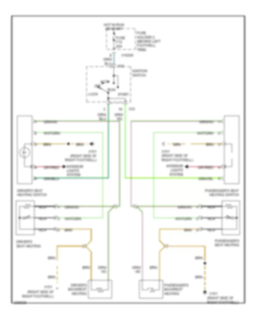
- Driver's seat heater
- Driver's seat heating switch
- Driver's seatback heater
- Eject box
- Fan control module, power steering
- Front cigar lighter
- Gear indicator light
- Gearshift lock
- General module control unit
- Hall sensor, driver's seat belt buckle
- Hall sensor, passenger's seat belt buckle
- Ignition coil
- Left side airbag satellite sensor
- Lighting, front right door opener
- Multiple restraint system control unit
- Nca
- Only
- Outside mirror, front passenger's side
- Passenger's door entrance light
- Passenger's seat belt buckle contact
- Passenger's seat heater
- Passenger's seat heating switch
- Passenger's seatback heater
- Passenger's side make-up mirror light
- Passengers door lock switch
- Radio control unit
- Right headlight
- Right side airbag satellite sensor
- Seat occupancy recognition
- Shield
- Shift lock elector level lock
- Universal electronic charging and hands-free module
- Volute spring
- W/ abs
- W/ cooper s
- W/ dsc
- W/ telephone provision
- W/ universal electronic charging and hands-free module
- W/o cooper s
- W/o traction control
- Windshield defroster, left heating zone
- X151 (right side of right footwell)
- X18170 (under center console)
- X18723 (behind right side trim panel)
- X4 (right rear of engine compt)
- X46 (under center console)
- X6000
- X6454
Электросхема подключение массы заземления (2 из 4) для MINI Cooper 2007
Электросхема подключение массы заземления (2 из 4) для MINI Cooper 2007 - Список элементов:
- 2006,
- Amplifier
- Boost radio
- Brake fluid level switch
- Cd changer
- Center brake light
- Central locking drive, trunk lid/ tailgate
- Central locking drive, trunk lid/tailgate
- Compt)
- Convertible
- Coupe
- Digital motor electronics control unit
- Diode
- Front left auxiliary flasher unit
- Front left turn signal
- Front right auxiliary flash unit
- Front right turn signal lamp
- Fuse holder iii
- Gear position switch
- General module control unit
- Headlight washer pump
- Horn for anti-theft alarm system
- Left fog light
- Left headlight
- Left horn
- Left parking light
- Left windshield washer jet heater
- License plate lights
- License plate lights (coupe)
- Luggage compartment light
- Microwave sensor, driver's door
- Microwave sensor, passenger's door
- Microwave sensor, rear left
- Microwave sensor, rear right
- Motor, electric fan i
- Navigation computer
- Nca
- On/off wiper motor relay
- Park distance control unit (pdc)
- Radio control unit (coupe)
- Rear fog light
- Rear right brake pad sensor
- Rear window
- Right fog right
- Right horn
- Right parking light
- Right storage compartment lock driver's unit
- Right storage compartment lock microswitch
- Right windshield washer jet heater
- Side marker light, left
- Side marker light, rear left
- Side marker light, rear right
- Side marker light, right
- Single- stage blower
- Steering control unit/ hydraulic pump
- Switch, trunk lid contact
- Switching unit, 2-stage blower
- Taillight, right
- Two- stage blower
- Underhood light switch
- W/ rear window antenna
- W/o rear window antenna
- Washer fluid level switch
- Washer pump
- Wave radio
- Wave trap 2
- Wiper motor
- X165 (right side of engine
- X167 (left side of engine compt)
- X173 (behind battery)
- X175 (left side of engine compt)
- X179 (partial) (coupe: right door, convertible: below right rear door)
- X490 (partial) (coupe: left rear side of luggage compt, convertible: left rear of trunk)
- X494 (right rear side of luggage compt)
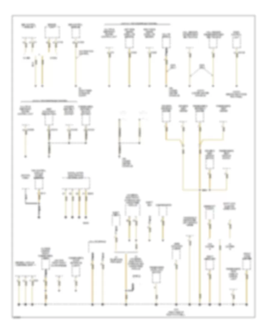
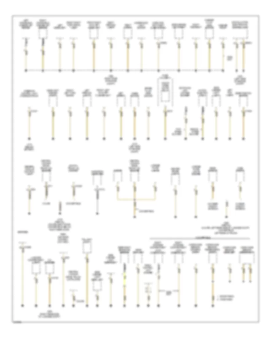
Электросхема подключение массы заземления (3 из 4) для MINI Cooper 2007
Электросхема подключение массы заземления (3 из 4) для MINI Cooper 2007 - Список элементов:
- (2005 early prod coupe)
- (2005 early prod)
- (2005 late prod)
- (2006, 2007)
- (except 2005 early prod)
- Automatic transmission central shift unit
- Blower motor
- Blower output stage
- Brake light switch
- Clutch switch module
- Control module, interior protection i
- Convertible
- Convertible soft top control module
- Coupe
- Driver's door entrance light
- Driver's side footwell light
- Electro- chromic interior rear-view mirror
- Electronic immobilizer control unit
- Fan relay, steering control module
- Fresh air/air recir- culation flap motor
- Front interior reading lamp
- Glove box light
- Heating & a/c control module
- Heating/ air con- ditioning control panel
- Instrument cluster control module
- Lighting, front left door opener
- Make-up mirror light, driver's side
- Make-up mirror light, passenger's side
- Microswitch for left storage compartment lock
- Mirror adjustment switch
- Nca
- Not used
- Obd ii connector
- On-board monitor control unit
- Outside mirror fold-in control unit
- Outside mirror, driver's side
- Passenger's side footwell light
- Radio control unit
- Rain sensor
- Rear window wiper motor
- Relay, front washer pump
- Relay, rear washer pump
- Relay, rear window wiper motor
- Sensor, interior temper- ature/ fan
- Steering angle sensor
- Sunroof control switch
- Sunroof module control unit
- Switch panel
- Switch, rear power window
- Switch, tire failure indicator
- System lock, driver's door
- Transmission control unit
- Turn indicator/ low beam switch
- W/ boost radio
- W/ ihka
- W/ wave radio
- W/o ihka
- W10 engine w/ a/t transmission
- W11 engine w/ egs transmission control
- Windshield defroster, right heating zone
- Windshield wiper switch
- X1108 (left door) (partial)
- X13016 (convertible: front of headliner, coupe: rear of headliner)
- X13230 (convertible: behind left door, coupe: left door entrance) (partial)
Электросхема подключение массы заземления (4 из 4) для MINI Cooper 2007
Электросхема подключение массы заземления (4 из 4) для MINI Cooper 2007 - Список элементов:
- 2005 late prod, 2006 & 2007
- Interior/ reading lamp, front
- Left drive unit for storage compartment lock
- Microswitch, cross brace
- Microswitch, rear window shelf
- Nca
- Relay 1, lock & sliding canvas sunroof
- Relay 2, lock & sliding canvas sunroof
- Relay, convertible top 1
- Relay, convertible top 2
- Storage compartment relay
- Sunroof control switch
- Sunroof module control unit
- W/ cvm convertible top & early 2005 coupe
- W/ cvm2 convertible top, 2005 late prod coupe & 2006-2007 coupe
- Windshield defroster right heating zone
- X179 (partial) (coupe: right door, convertible: below right rear door)
- X490 (partial) (coupe: left rear side of luggage compartment, convertible: left rear of trunk)
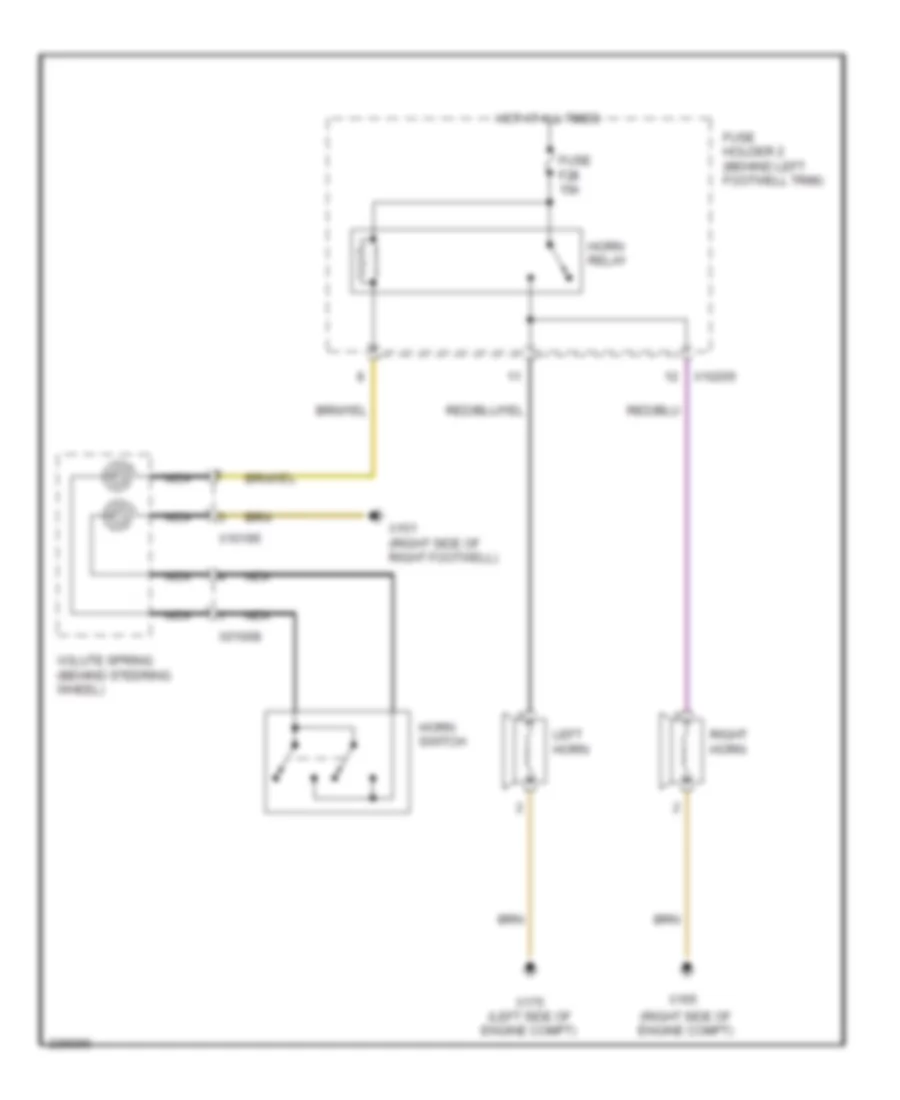
Звуковой сигнал Гудок
Электросхема звукового сигнал Гудка для MINI Cooper 2007
Электросхема звукового сигнал Гудка для MINI Cooper 2007 - Список элементов:
- (right side of engine compt)
- Fuse f28 15a
- Fuse holder 2 (behind left footwell trim)
- Horn relay
- Horn switch
- Hot at all times
- Left horn
- Nca
- Right horn
- Volute spring (behind steering wheel)
- X01008
- X10195
- X10205
- X151 (right side of right footwell)
- X165
- X175 (left side of engine compt)
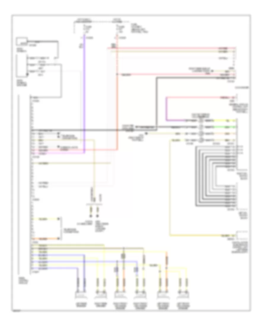
Магнитола Мультимедия
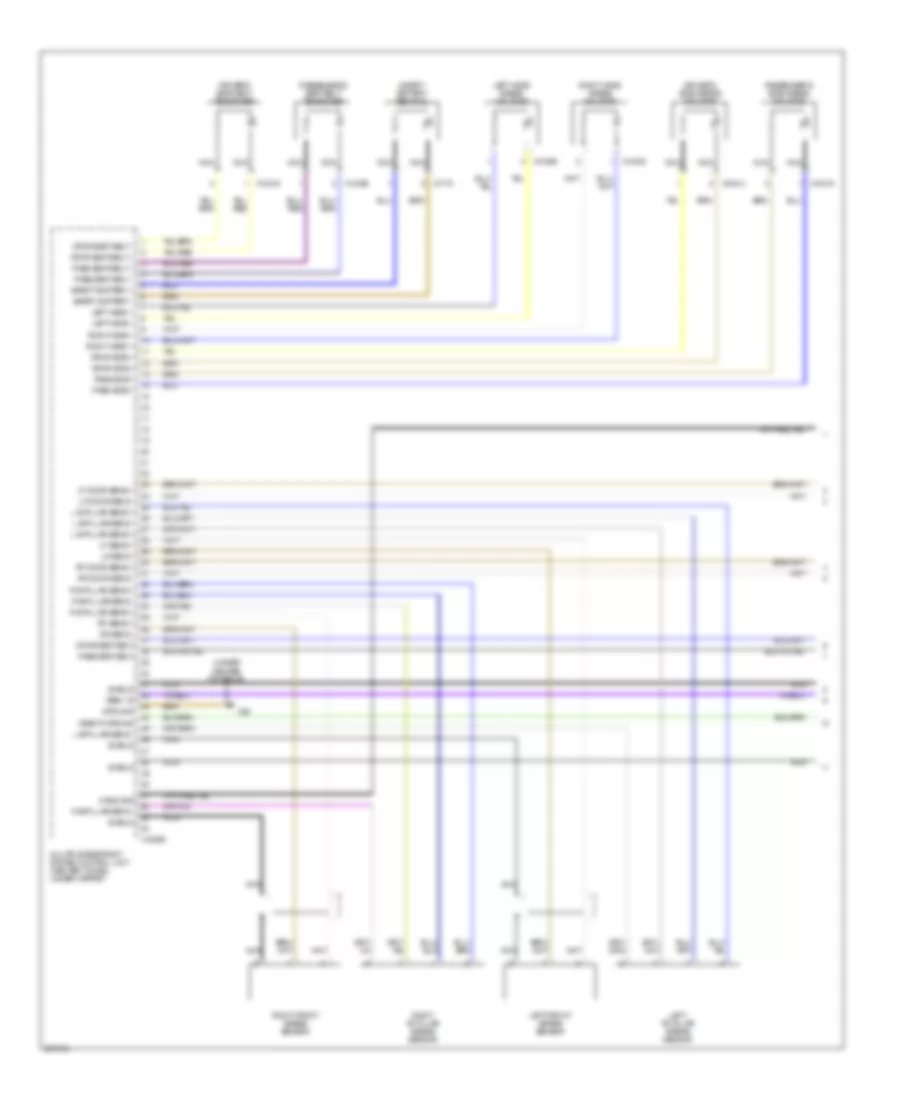
Эдектросхема магнитолы. Базовая комплектация., С Телефонные Условия для MINI Cooper 2007
Эдектросхема магнитолы. Базовая комплектация., С Телефонные Условия для MINI Cooper 2007 - Список элементов:
- (right rear side of luggage compt) x494
- Am/fm
- Am/fm antenna
- Am/fm antenna amplifier
- Cd changer
- Computer data lines system
- Contact spring (volute spring)
- Convertible
- Coupe
- Digital motor electronics control unit (left rear engine compt)
- Fuse f10 5a
- Fuse f27 15a
- Fuse holder 2 (behind left footwell trim)
- General module control unit (behind right footwell)
- Hot at all times
- Hot in accy, run and start
- Interior lights system
- Left front high-range speaker
- Left front mid-range speaker
- Left mfl switch block
- Left rear speaker
- Nca
- Radio control module
- Right front high-range speaker
- Right front mid-range speaker
- Right mfl switch block
- Right rear speaker
- Telephone connections
- X01000
- X01001
- X01002
- X01003
- X01068
- X01104
- X10195
- X10205
- X10206
- X13016 (in headliner)
- X13364
- X13647
- X151 (right side of footwell)
- X1532
- X18126
- X18180
- X18805
- X255
- X494 (right rear side of luggage compt.)
- X60004
- X807
- X813
- X9960
Эдектросхема магнитолы. Базовая комплектация., без Телефонные Условия для MINI Cooper 2007
Эдектросхема магнитолы. Базовая комплектация., без Телефонные Условия для MINI Cooper 2007 - Список элементов:
- (right rear side of luggage compt) x494
- Am/fm
- Am/fm antenna
- Am/fm antenna amplifier
- Cd changer
- Computer data lines system
- Contact spring (volute spring)
- Convertible
- Coupe
- Digital motor electronics control unit (left rear engine compt)
- Fuse f10 5a
- Fuse f27 15a
- Fuse holder 2 (behind left footwell trim)
- General module control unit (behind right footwell)
- Hot at all times
- Hot in accy, run and start
- Interior lights system
- Left front mid-range speaker
- Left front tweeter speaker
- Left mfl switch block
- Left rear speaker
- Nca
- Radio control module
- Right front mid-range speaker
- Right front tweeter speaker
- Right mfl switch block
- Right rear speaker
- X01000
- X01001
- X01002
- X01003
- X01068
- X01104
- X10195
- X10205
- X10206
- X13016 (in headliner)
- X13364
- X151 (right side of footwell)
- X18180
- X2519
- X255
- X494 (right rear side of luggage compt.)
- X60004
- X807
- X813
- X9345
- X9960
Электросхема премиум магнитолы (1 из 2) для MINI Cooper 2007
Электросхема премиум магнитолы (1 из 2) для MINI Cooper 2007 - Список элементов:
- (convertible)
- (coupe)
- Am/fm
- Amplifier
- Amplifier (convertible: below passenger's seat) (coupe: right side of luggage compt)
- Antenna
- Fuse f10 5a
- Fuse f27 15a
- Fuse holder 2 (behind left footwell trim)
- Hot at all times
- Hot in accy, run and start
- Interior lights system
- Nca
- Radio control module
- Telephone connections
- X01068
- X01104
- X10205
- X10206
- X10266
- X13016 (in headliner)
- X13364
- X13647
- X1532
- X18126
- X18805
- X494 (right rear of luggage compt.)
- X494 (right rear side of luggage compt)
- X807
- X813
Электросхема премиум магнитолы (2 из 2) для MINI Cooper 2007
Электросхема премиум магнитолы (2 из 2) для MINI Cooper 2007 - Список элементов:
- (right rear side of luggage compt) x494
- (under left front seat) navigation computer
- Cd changer
- Computer data lines system
- Contact spring (volute spring)
- Digital motor electronics control unit (left rear of engine compt)
- General module control unit (behind right footwell)
- Left front mid-range speaker
- Left front tweeter speaker
- Left mfl switch block
- Left rear speaker
- Nca
- Right front mid-range speaker
- Right front tweeter speaker
- Right mfl switch block
- Right rear speaker
- W/ hifi
- W/o hifi
- X01000
- X01001
- X01002
- X01003
- X10195
- X1261
- X1312
- X151 (right side of right footwell)
- X18180
- X18514
- X18515
- X255
- X397
- X60004
- X9960
Навигация GPS Парктроники
Электросхема навигации GPS для MINI Cooper 2007
Электросхема навигации GPS для MINI Cooper 2007 - Список элементов:
- (convertible: under left rear seat) (coupe: left door)
- (right rear of engine compt)
- Abs control module
- Abs control module (right rear of engine compt)
- Abs/dsc control module
- Amplifier (below passenger's seat) (convertible) (right side of luggage compt) (coupe)
- Computer data lines system
- Exterior lights, mirrors, transmissions systems
- Fuse f10 5a
- Fuse f22 15a
- Fuse holder 2 (behind left footwell trim)
- Gps antenna
- Hot at all times
- Hot in accy run and start
- Mirrors system
- Navigation computer (under right front seat) (coupe) (under left front seat) (convertible)
- Nca
- On-board monitor
- Radio control unit
- Red
- Switch panel
- W/ dsc
- W/ premium radio
- W/o dsc & w/ traction control
- W/o dsc & w/o traction control
- W/o premium radio
- X10201
- X10202
- X10266
- X11
- X11525
- X1312
- X1313
- X13230
- X1532
- X1746
- X179 (convertible: below right rear seat) (coupe: right door)
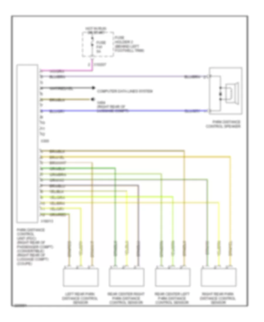
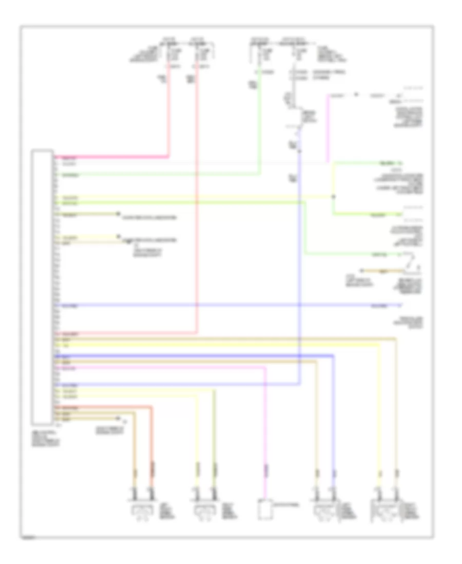
Электросхема парктроников для MINI Cooper 2007
Электросхема парктроников для MINI Cooper 2007 - Список элементов:
- Computer data lines system
- Fuse f41 5a
- Fuse holder 2 (behind left footwell trim)
- Hot in run or start
- Left rear park distance control sensor
- Park distance control speaker
- Park distance control unit (pdc) (right rear of passenger compt) (convertible) (right rear of luggage compt) (coupe)
- Rear center left park distance control sensor
- Rear center right park distance control sensor
- Right rear park distance control sensor
- X10207
- X18013
- X300
- X494 (right rear of luggage compt)
Подогрев стекол и зеркал
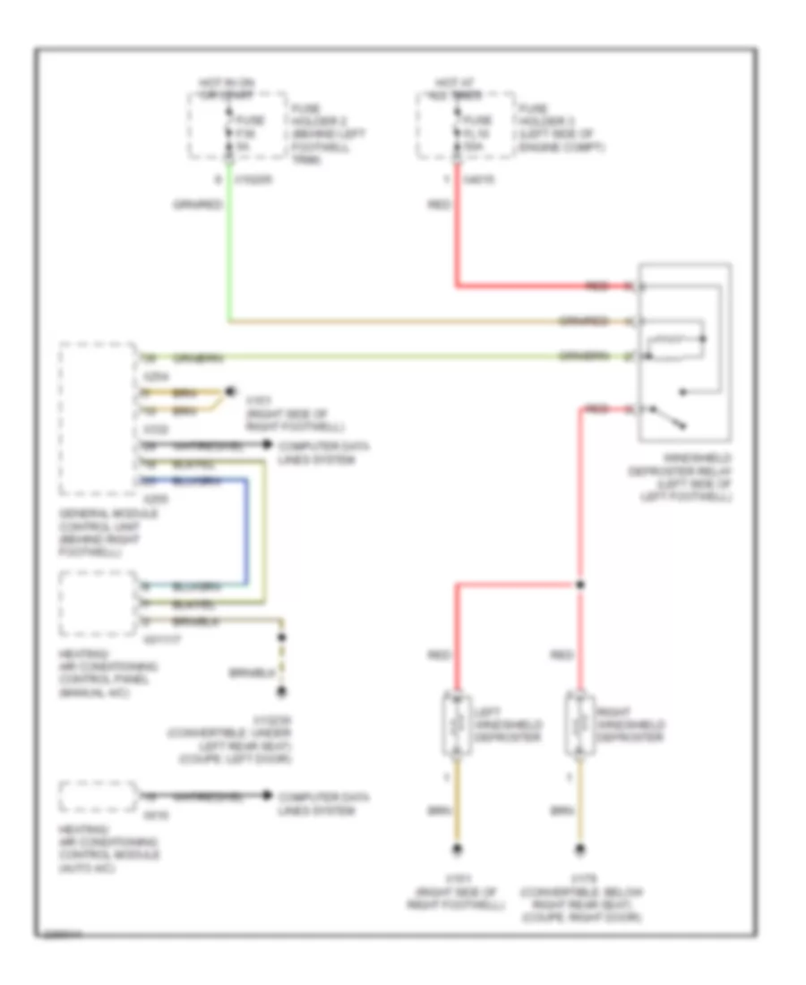
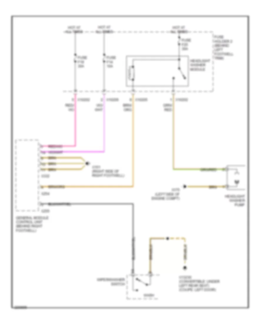
Электросхема подогрева лобового стекла для MINI Cooper 2007
Электросхема подогрева лобового стекла для MINI Cooper 2007 - Список элементов:
- Computer data lines system
- Fuse f36 5a
- Fuse fl10 50a
- Fuse holder 2 (behind left footwell trim)
- Fuse holder 3 (left side of engine compt)
- General module control unit (behind right footwell)
- Heating/ air conditioning control module (auto a/c)
- Heating/ air conditioning control panel (manual a/c)
- Hot at all times
- Hot in on or start
- Left windshield defroster
- Red
- Right windshield defroster
- Windshield defroster relay (left side of left footwell)
- X01117
- X10205
- X13230 (convertible: under left rear seat) (coupe: left door)
- X151 (right side of right footwell)
- X179 (convertible: below right rear seat) (coupe: right door)
- X254
- X255
- X332
- X4015
- X610
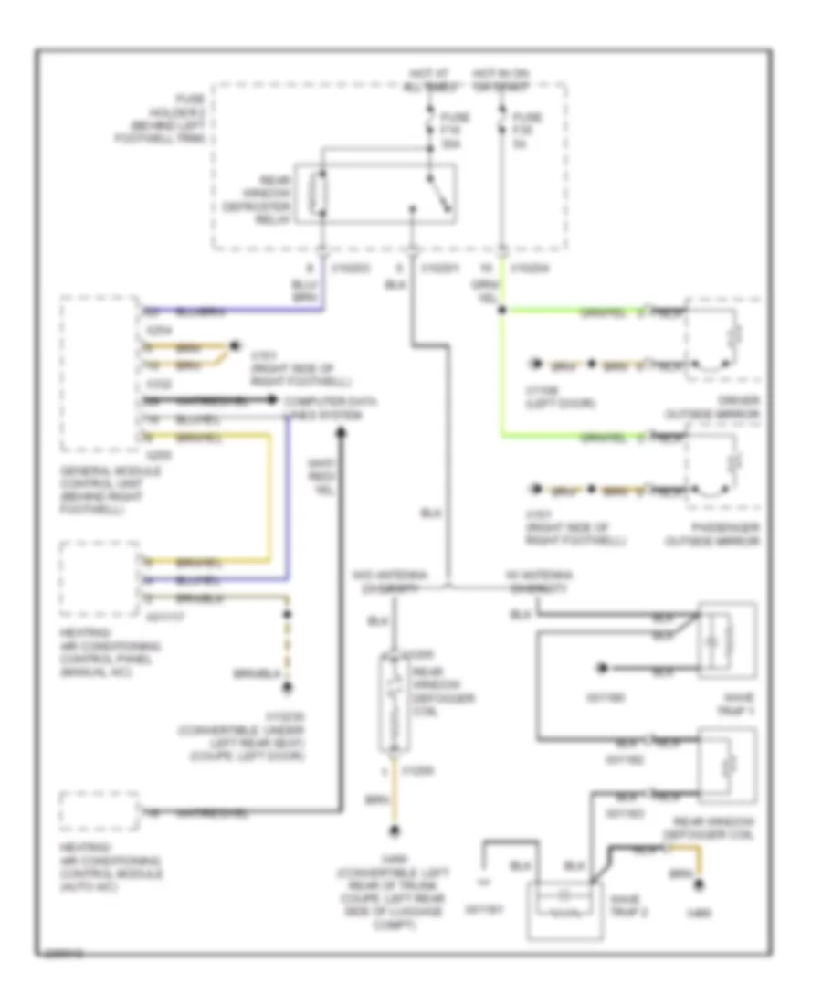
Электросхема подогрева заднего стекла и зеркал заднего вида для MINI Cooper 2007
Электросхема подогрева заднего стекла и зеркал заднего вида для MINI Cooper 2007 - Список элементов:
- Computer data lines system
- Driver outside mirror
- Fuse f16 30a
- Fuse f35 5a
- Fuse holder 2 (behind left footwell trim)
- General module control unit (behind right footwell)
- Heating/ air conditioning control module (auto a/c)
- Heating/ air conditioning control panel (manual a/c)
- Hot at all times
- Hot in on or start
- Nca
- Passenger outside mirror
- Rear window defogger coil
- Rear window defroster relay
- W/ antenna diversity
- W/o antenna diversity
- Wave trap 1
- Wave trap 2
- X01117
- X01180
- X01181
- X01182
- X01183
- X10201
- X10203
- X10204
- X1108 (left door)
- X1265
- X1266
- X13230 (convertible: under left rear seat) (coupe: left door)
- X151 (right side of right footwell)
- X254
- X255
- X332
- X490
- X490 (convertible: left rear of trunk coupe: left rear side of luggage compt)
ПОДУШКИ БЕЗОПАСНОСТИ AIR BAG
Электросхема подушек безопасности SRS AirBag (1 из 2) для MINI Cooper 2007
Электросхема подушек безопасности SRS AirBag (1 из 2) для MINI Cooper 2007 - Список элементов:
- (under center console)
- Deactivate ind
- Driver's seat belt tensioner
- Driver's side airbag inflator
- Drvr seat belt
- Drvr seat belt +
- Drvr seat belt -
- Drvr side +
- Drvr side -
- Ground
- K-bus sig
- L b-pillar sens +
- L b-pillar sens -
- Left "b" pillar airbag sensor
- Left front airbag sensor
- Left head +
- Left head -
- Left head airbag inflator
- Lf door sens +
- Lf door sens -
- Lf sens +
- Lf sens -
- Multiple restraint system control unit (center tunnel under carpet)
- Nca
- Pass seat belt
- Pass seat belt +
- Pass seat belt -
- Pass side +
- Pass side -
- Passenger's seat belt tensioner
- Passenger's side airbag inflator
- R b-pillar sens +
- R b-pillar sens -
- Rf door sens +
- Rf door sens -
- Rf sens +
- Rf sens -
- Right "b" pillar airbag sensor
- Right front airbag sensor
- Right head +
- Right head -
- Right head airbag inflator
- Safety battery +
- Safety battery -
- Safety battery terminal
- Shield
- Term 15
- X10214
- X10215
- X10216
- X10395
- X10400
- X10429
- X1770
- X18069
- X46
Электросхема подушек безопасности SRS AirBag (2 из 2) для MINI Cooper 2007
Электросхема подушек безопасности SRS AirBag (2 из 2) для MINI Cooper 2007 - Список элементов:
- (under center console) x46
- Computer data lines system
- Driver's airbag inflator assemblies
- Driver's seat belt buckle contact
- Drvr airbag +
- Drvr airbag -
- Fuse f18 5a
- Fuse holder 2 (behind left footwell trim)
- Hot in accy, run and start
- Instrument cluster control module
- K-bus sig
- Left front door airbag sensor
- Multiple restraint system control unit (center tunnel under carpet)
- Nca
- Pass airbag +
- Pass airbag -
- Passenger airbag deactivation indicator lamp
- Passenger's airbag inflator assemblies
- Passenger's seat belt buckle contact
- Right front door airbag sensor
- Seat occupancy recognition
- Volute spring
- X01099
- X10179
- X10203
- X11175
- X46 (under center console)
- X548
- X783
ПРЕДУПРЕЖДАЮЩИЕ СИСТЕМЫ
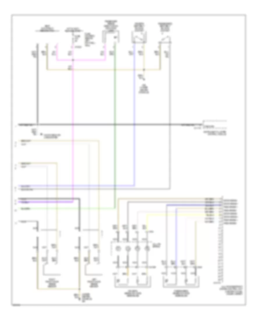
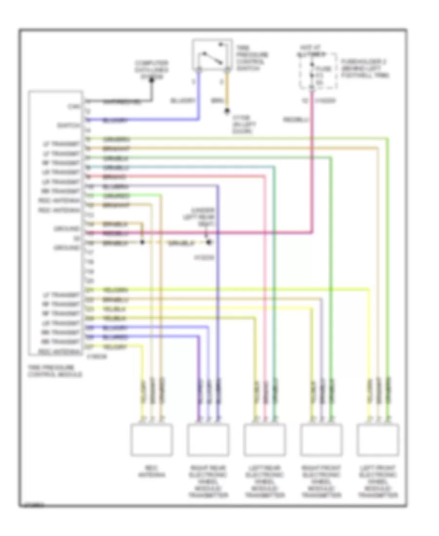
Электросхема системы контроля давления в шинах для MINI Cooper 2007
Электросхема системы контроля давления в шинах для MINI Cooper 2007 - Список элементов:
- (under left rear seat)
- Can
- Computer data lines system
- Fuse f3 5a
- Fuseholder 2 (behind left footwell trim)
- Ground
- Hot at all times
- Left front electronic wheel module/ transmitter
- Left rear electronic wheel module/ transmitter
- Lf transmit
- Lr transmit
- Rdc antenna
- Rf transmit
- Right front electronic wheel module/ transmitter
- Right rear electronic wheel module/ transmitter
- Rr transmit
- Switch
- Tire pressure control module
- Tire pressure control switch
- X10200
- X1108 (in left door)
- X13230
- X18034
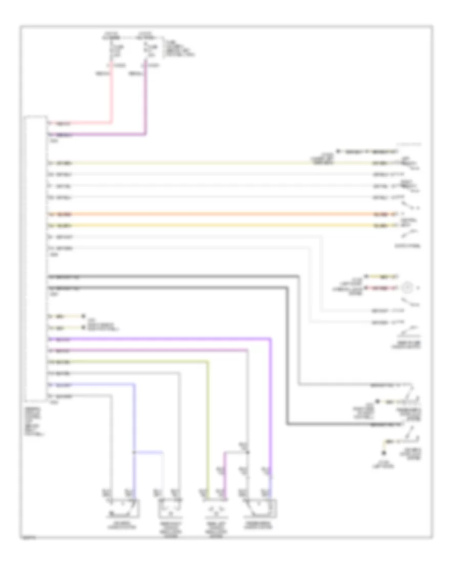
ПРИБОРНАЯ ПАНЕЛЬ
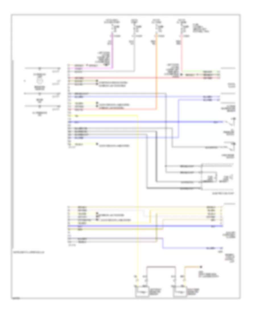
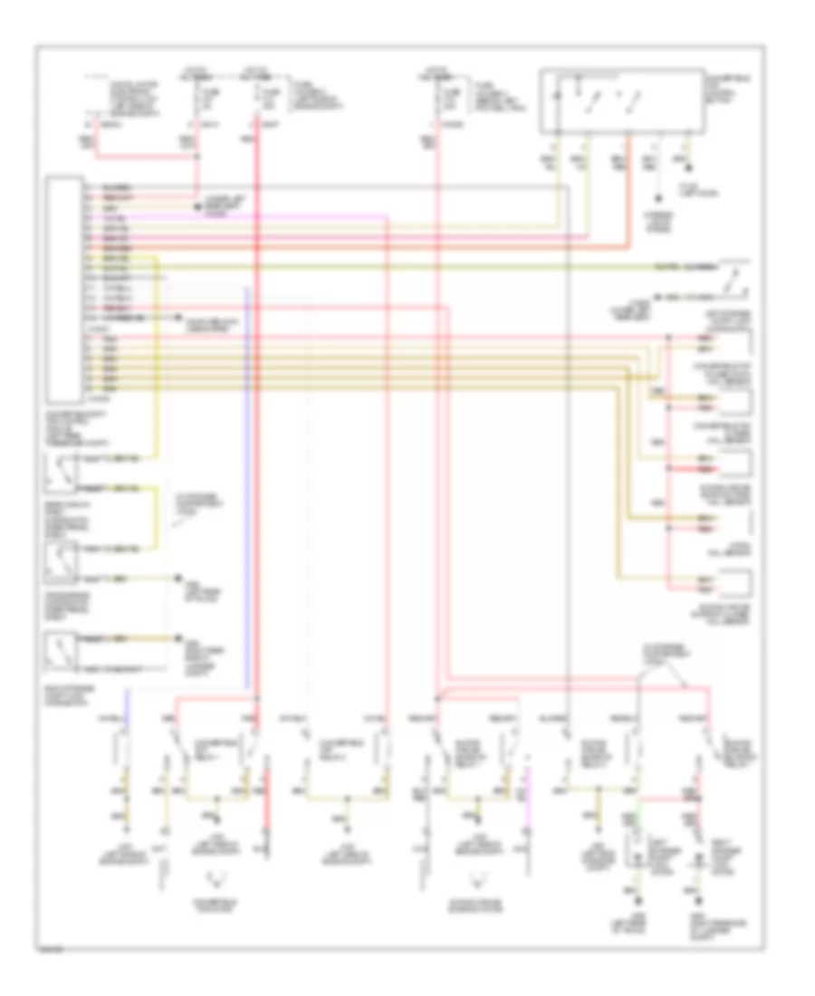
Электросхема панели приборов для MINI Cooper 2007
Электросхема панели приборов для MINI Cooper 2007 - Список элементов:
- (left door) (coupe) (under left rear seat) (convertible) x13230
- Auxiliary instrument cluster
- Brake ind
- Brake pad wear ind
- Charge ind lamp
- Computer data lines system
- Digital clock
- Electric fuel pump
- Exterior lights system
- Exterior lights systems
- Fuel level sensor 1
- Fuel level sensor 2
- Fuse fuse f21 10a
- Fuse fuse f3 5a
- Fuse fuse f5 5a
- Fuse fuse f9 5a
- Fuse holder 2 (behind left footwell trim)
- General module control unit
- Hand brake switch
- Hot at all times
- Hot in accy, run and start
- Hot in start
- Instrument cluster module
- Interior lights system
- Left front brake pad sensor
- Oil pressure ind
- Oil pressure switch
- Outside temperature sensor
- Right rear brake pad sensor
- Starting/charging system
- X10200
- X10202
- X10206
- X11175
- X11177
- X255
- X494 (right rear side of luggage compt)
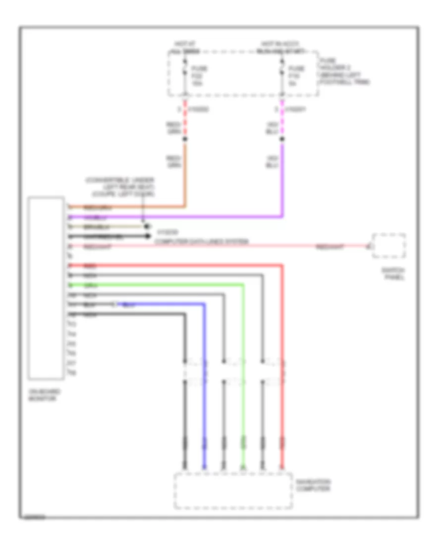
бортовая компьютерная схема для MINI Cooper 2007
бортовая компьютерная схема для MINI Cooper 2007 - Список элементов:
- (convertible: under left rear seat) (coupe: left door)
- Computer data lines system
- Fuse f10 5a
- Fuse f22 15a
- Fuse holder 2 (behind left footwell trim)
- Hot at all times
- Hot in accy, run and start
- Navigation computer
- Nca
- On-board monitor
- Red
- Switch panel
- X10201
- X10202
- X13230
ПРИВОД ЗЕРКАЛ
Электросхема затемняющегося зеркала заднего вида для MINI Cooper 2007
Электросхема затемняющегося зеркала заднего вида для MINI Cooper 2007 - Список элементов:
- (lower left of transmission)
- A/t
- Back-up light switch
- Cvt switch (except cooper s)
- Electrochromic rear view mirror
- Exterior lights, transmission, & navigation system
- Fuse f13 5a
- Fuse f35 5a
- Fuse holder 2 (behind left footwell trim)
- Gear position switch (cooper s)
- General module control unit (behind right footwell)
- Hot in on or start
- M/t
- X10204
- X10206
- X13230 (convertible: (under left rear seat) (coupe: left door)
- X254
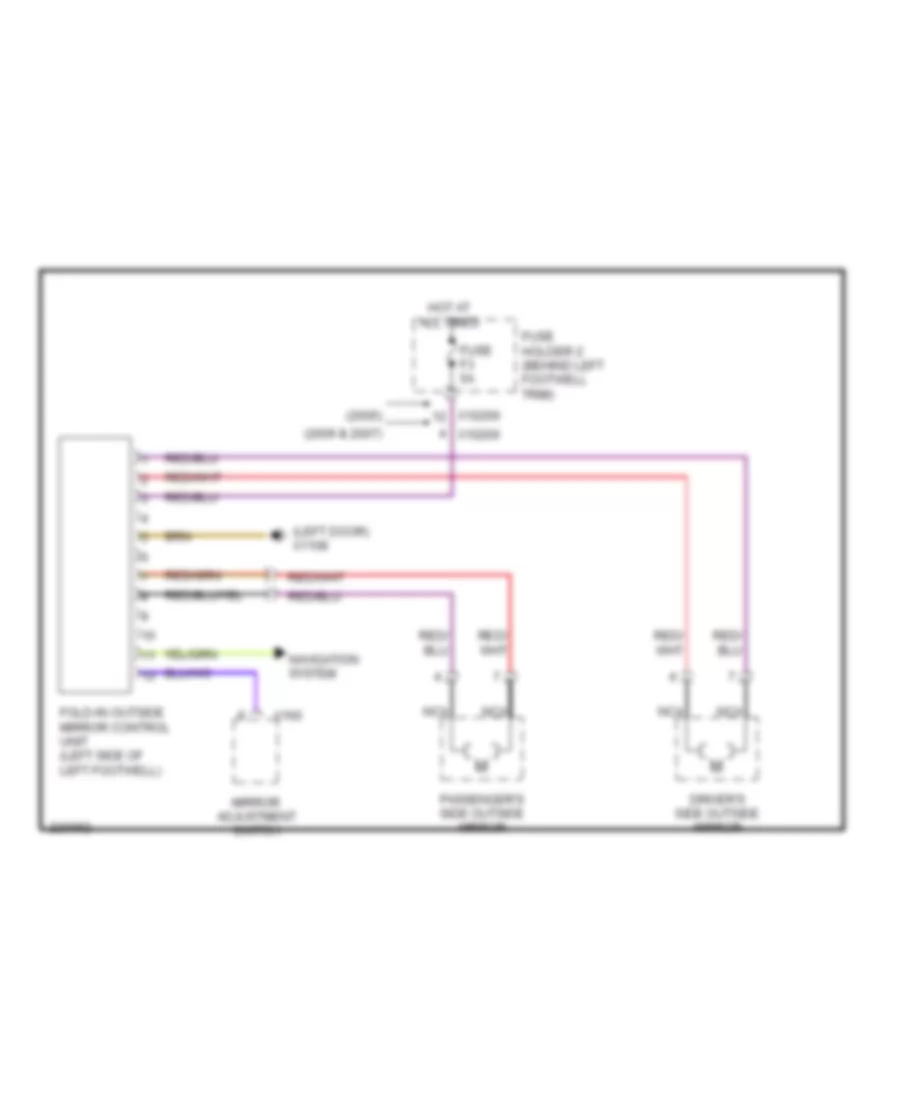
Электросхема складывания зеркал заднего вида для MINI Cooper 2007
Электросхема складывания зеркал заднего вида для MINI Cooper 2007 - Список элементов:
- (2005)
- (2006 & 2007)
- (left door) x1108
- Driver's side outside mirror
- Fold-in outside mirror control unit (left side of left footwell)
- Fuse f3 5a
- Fuse holder 2 (behind left footwell trim)
- Hot at all times
- Mirror adjustment switch
- Navigation system
- Nca
- Passenger's side outside mirror
- X10200
- X160
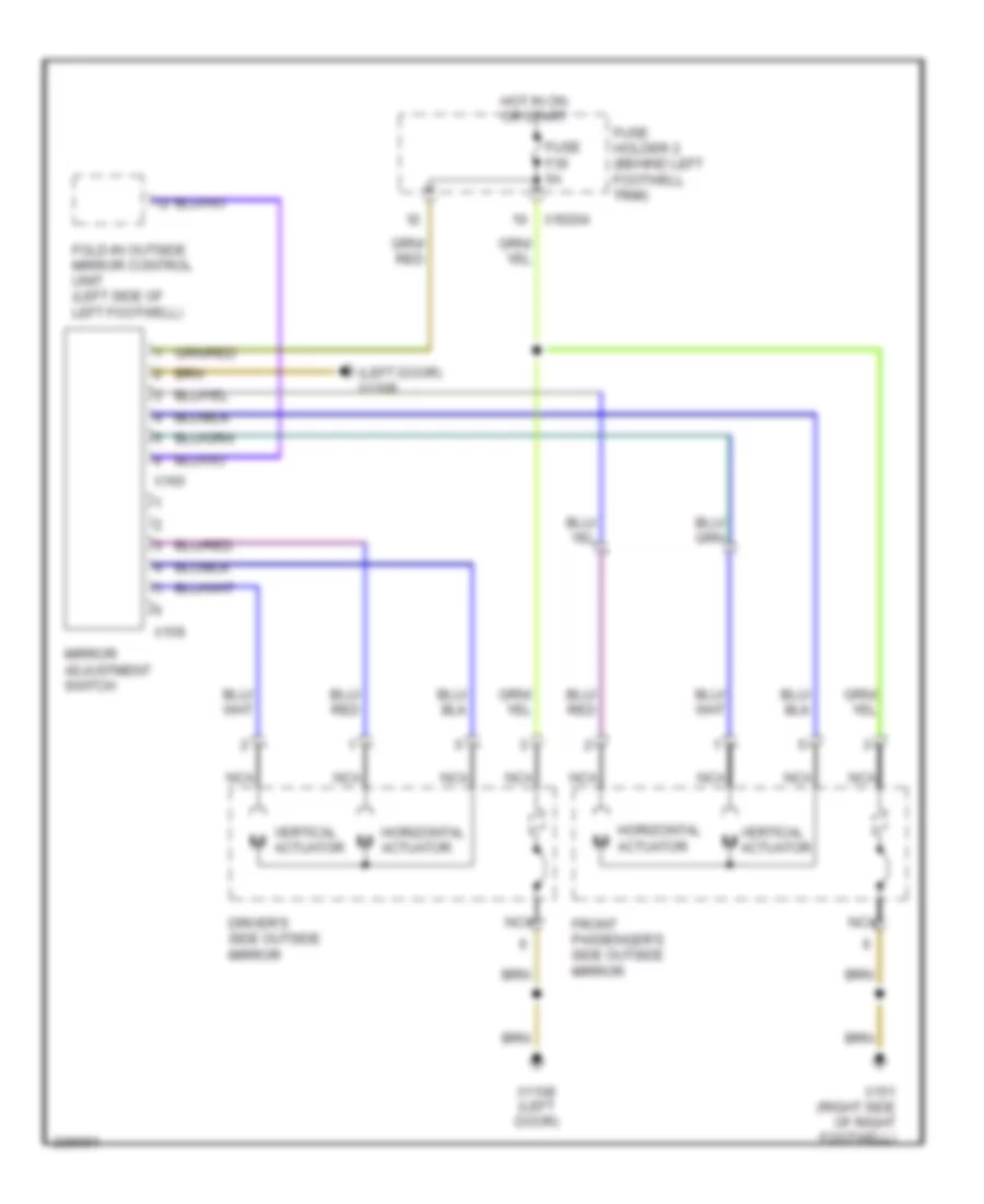
Электросхема привода зеркал для MINI Cooper 2007
Электросхема привода зеркал для MINI Cooper 2007 - Список элементов:
- (left door) x1108
- Driver's side outside mirror
- Fold-in outside mirror control unit (left side of left footwell)
- Front passenger's side outside mirror
- Fuse f35 5a
- Fuse holder 2 (behind left footwell trim)
- Horizontal actuator
- Hot in on or start
- Mirror adjustment switch
- Nca
- Vertical actuator
- Vertical m actuator
- X10204
- X1108 (left door)
- X151 (right side of right footwell)
- X159
- X160
ПРИВОД ЛЮКА И КРЫШИ
Электросхема складной крыши для MINI Cooper 2007
Электросхема складной крыши для MINI Cooper 2007 - Список элементов:
- (under left rear seat) x13230
- (w/ storage compartment lock)
- Catch hall sensor
- Computer data lines system
- Convertible soft top control module (left rear passenger compt)
- Convertible top closed hall sensor
- Convertible top control button
- Convertible top folded down hall sensor
- Convertible top motor
- Convertible top relay 1
- Convertible top relay 2
- Cross brace microswitch (rear parcel shelf)
- Digital motor electronic control unit (left side of engine compt)
- Fuse f01 5a
- Fuse f15 20a
- Fuse fl3 40a
- Fuse holder 2 (behind left footwell trim)
- Fuse holder 3 (left side of engine compt)
- Hot at all times
- Interior lights system
- Left storage compt lock microswitch
- Left storage compt lock motor
- Nca
- Rear window shelf microswitch (rear parcel shelf)
- Red
- Right storage compt lock motor
- Right storage compt lock microswitch
- Sliding canvas sunroof motor
- Sliding canvas sunroof closed hall sensor
- Sliding canvas sunroof open hall sensor
- Sliding canvas sunroof relay 1
- Sliding canvas sunroof relay 2
- X10206
- X1108 (left door)
- X13037
- X13038
- X13230 (under left rear seat)
- X167 (left side of engine compt)
- X4007
- X4013
- X490 (left rear of trunk)
- X494 (right rear side of luggage compt)
- X60004
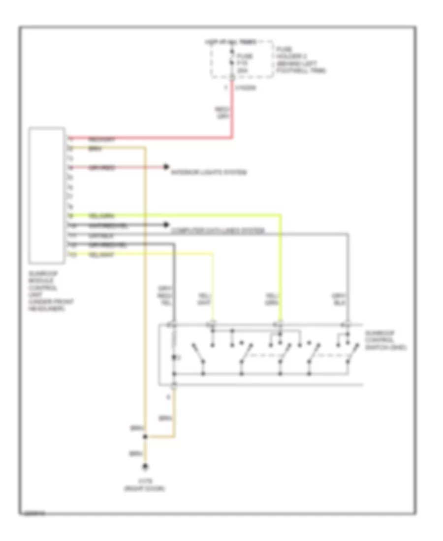
Электросхема привода люка для MINI Cooper 2007
Электросхема привода люка для MINI Cooper 2007 - Список элементов:
- Computer data lines system
- Fuse f15 20a
- Fuse holder 2 (behind left footwell trim)
- Hot at all times
- Interior lights system
- Sunroof control switch (shd)
- Sunroof module control unit (under front headliner)
- X10206
- X179 (right door)
ПРИВОД СТЕКЛОПОДЪЕМНИКОВ
Электросхема стеклоподъемников, Кабриолет для MINI Cooper 2007
Электросхема стеклоподъемников, Кабриолет для MINI Cooper 2007 - Список элементов:
- Central lock
- Driver's door lock system
- Driver's window motor
- Fuse f1 30a
- Fuse f19 30a
- Fuse holder 2 (behind left footwell trim)
- General module control unit (behind right footwell)
- Hot at all times
- Interior lights system
- Left window
- Passenger's door lock system
- Passenger's window motor
- Rear left window regulator motor
- Rear power window switch
- Rear right window regulator motor
- Right window
- Switch panel
- X10201
- X10202
- X1108 (left door)
- X13230 (under left rear seat)
- X151 (right side of right footwell)
- X253
- X255
- X332
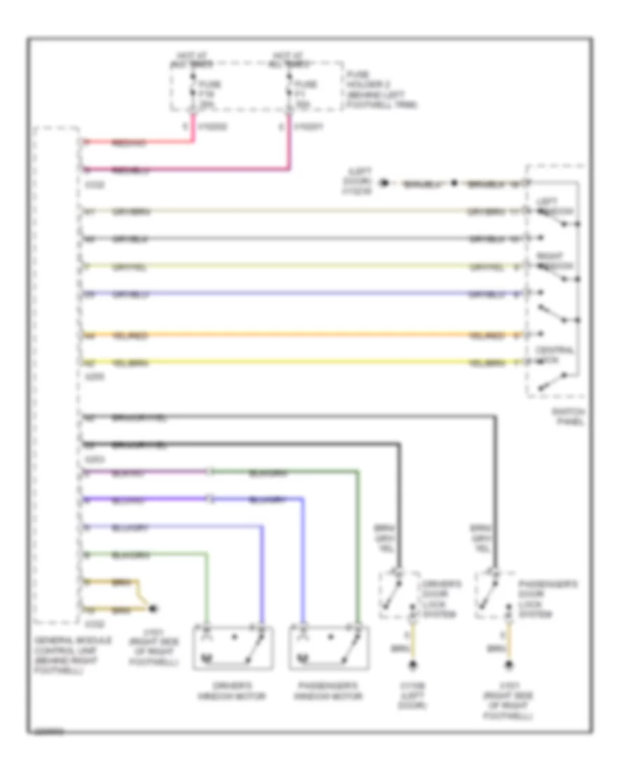
Электросхема стеклоподъемников, Кабриолет Except для MINI Cooper 2007
Электросхема стеклоподъемников, Кабриолет Except для MINI Cooper 2007 - Список элементов:
- (left door) x13230
- (right side of right footwell)
- Central lock
- Driver's door lock system
- Driver's window motor
- Fuse f1 30a
- Fuse f19 30a
- Fuse holder 2 (behind left footwell trim)
- General module control unit (behind right footwell)
- Hot at all times
- Left window
- Passenger's door lock system
- Passenger's window motor
- Right window
- Switch panel
- X10201
- X10202
- X1108 (left door)
- X151
- X151 (right side of right footwell)
- X253
- X255
- X332
Противоугонная система Сигнализация
Электросхема противоугонной сигнализации, Кабриолет для MINI Cooper 2007
Электросхема противоугонной сигнализации, Кабриолет для MINI Cooper 2007 - Список элементов:
- (left door) x1108
- (left rear of trunk)
- (right side of engine compt)
- Central locking drive, trunk lid/tailgate (center rear of trunk)
- Computer data lines system
- Diode
- Driver's door lock
- Driver's door microwave sensor
- Fuel filler door lock
- Fuse f1 30a
- Fuse f14 10a
- Fuse f19 30a
- Fuse f23 20a
- Fuse f24 5a
- Fuse f4 5a
- Fuse f7 5a
- Fuse fl 12 50a
- Fuse fl 8 50a
- Fuse holder 2 (behind left footwell trim)
- Fuse holder 3 (left side of engine compt)
- General module control unit (behind right footwell)
- Hot at all times
- Hot in accy, run and start
- License plate lights
- Not used
- Passenger's door lock
- Passenger's door microwave sensor
- Rear left microwave sensor
- Rear right microwave sensor
- Red
- Siren w/ tilt alarm sensor
- Switch panel
- Theft ind
- Trunk lid contact switch
- Turn signal/ headlight dimmer switch
- Underhood light switch
- X10200
- X10201
- X10202
- X10206
- X10207
- X1108 (left door)
- X13230 (under left rear seat)
- X151 (right side of right footwell)
- X165
- X165 (right side of engine compt)
- X179 (below right rear seat)
- X253
- X254
- X255
- X332
- X4009
- X4010
- X490
- X490 (left rear of trunk)
- X494 (right rear side of luggage compt)
Электросхема противоугонной сигнализации, Кабриолет Except для MINI Cooper 2007
Электросхема противоугонной сигнализации, Кабриолет Except для MINI Cooper 2007 - Список элементов:
- (left door) x1108
- (left rear side of luggage compt)
- (not used)
- (right side of engine compt)
- Central locking drive, trunk lid/tailgate
- Central locking remote control (under front headliner)
- Computer data lines system
- Driver's door lock
- Fuel filler door lock
- Fuse f1 30a
- Fuse f14 10a
- Fuse f19 30a
- Fuse f23 20a
- Fuse f24 5a
- Fuse f4 5a
- Fuse f7 5a
- Fuse fl 12 50a
- Fuse fl 8 50a
- Fuse holder 2 (behind left footwell trim)
- Fuse holder 3 (left side of engine compt)
- General module control unit (behind right footwell)
- Hot at all times
- Hot in accy, run and start
- Interior protection 1 control module (in headliner)
- License plate lights
- Passenger's door lock
- Power distribution system
- Red
- Siren w/ tilt sensor
- Switch panel
- Theft ind
- Turn signal/ headlight dimmer switch
- Underhood light switch
- X10200
- X10201
- X10202
- X10206
- X10207
- X1108 (left door)
- X13230 (left door)
- X151 (right side of right footwell)
- X165
- X165 (right side of engine compt)
- X179 (right door)
- X253
- X254
- X255
- X332
- X4009
- X4010
- X490
- X494 (right rear side of luggage compt)
Электросхема иммобилайзера для MINI Cooper 2007
Электросхема иммобилайзера для MINI Cooper 2007 - Список элементов:
- (convertible: under left rear seat)
- (coupe: left door)
- Acc lock
- Clutch switch module (m/t)
- Computer data lines system
- Digital motor electronics control unit (left side of engine compt)
- Electronic immobilizer control unit (left side of dash)
- Fuse f24 5a
- Fuse f5 5a
- Fuse f6 5a
- Fuse holder 2 (behind left footwell trim)
- Hot at all times
- Hot in accy, run and start
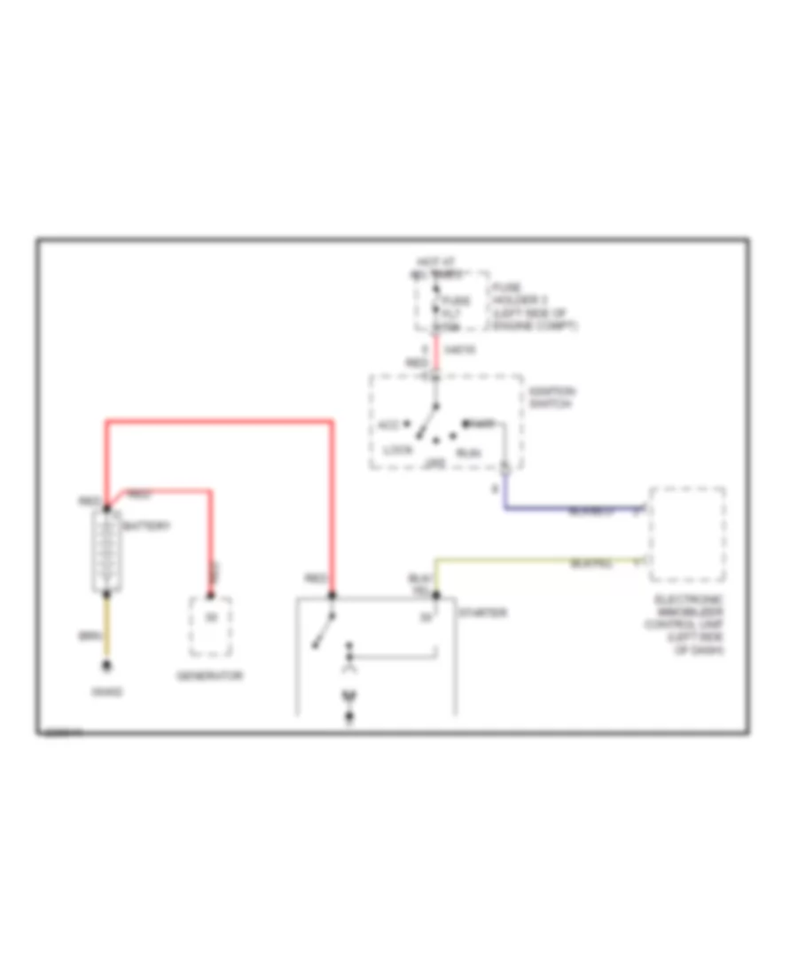
- Ignition switch
- Instrument cluster control module
- Off
- Start
- Starting/ charging system
- Toroidal coil
- Transmissions system
- X10199
- X10200
- X11177
- X13230
- X33
- X60004
СИСТЕМА АНТИБЛОКИРОВОЧНОЙ ТОРМОЗНОЙ СИСТЕМЫ ABS
Электросхема антиблокировочной тормозной системы АБС (ABS), С Динамическое Управление Стабильностью для MINI Cooper 2007
Электросхема антиблокировочной тормозной системы АБС (ABS), С Динамическое Управление Стабильностью для MINI Cooper 2007 - Список элементов:
- (2006 early prod)
- (left door) (coupe) (under left rear seat) (convertible)
- (lower steering column) steering angle sensor
- (others)
- (right rear of engine compt)
- Abs/dsc unit (right rear of engine compt)
- Brake fluid level switch (left side of engine compt)
- Brake light switch
- Computer data lines system
- Digital motor electronics control unit (left rear engine compt)
- Dsc sensor (transverse acceleration sensor) (under lever cover)
- Fuse f06 30a
- Fuse f2 5a
- Fuse f33 10a
- Fuse f40 5a
- Fuse f6 5a
- Fuse fl6 40a
- Fuse holder 2 (behind left footwell trim)
- Fuse holder 3 (left side of engine compt)
- Hot at all times
- Hot in accy, run and start
- Hot in on or start
- Left front speed sensor
- Left rear speed sensor
- Navigation computer (under right front seat) (coupe) (under left front seat) (convertible)
- Nca
- Outside mirror fold-in control unit (left side of left footwell)
- Pressure sensor (in left water box)
- Right front speed sensor
- Right rear speed sensor
- Switch panel
- Tire pressure warning (rdm) switch
- X10200
- X10205
- X10207
- X1313
- X13230
- X1746
- X175 (left side of engine compt)
- X4 (right rear of engine compt)
- X4010
- X4013
- X6004
Anti-lock Brakes Wiring Diagram, withTraction Control & without Динамическое Управление Стабильностью для MINI Cooper 2007
Anti-lock Brakes Wiring Diagram, withTraction Control & without Динамическое Управление Стабильностью для MINI Cooper 2007 - Список элементов:
- (2006 early prod)
- (others)
- (right rear of engine compt)
- Abs control module (right rear of engine compt)
- Brake fluid level switch (in brake fluid reservoir)
- Brake light switch
- Computer data lines system
- Digital motor electronics control unit (left rear engine compt)
- Fuse f06 30a
- Fuse f33 10a
- Fuse f6 5a
- Fuse fl6 40a
- Fuse holder 2 (behind left footwell trim)
- Fuse holder 3 (left side of engine compt)
- Hot at all times
- Hot in accy, run and start
- Hot in on or start
- Left front speed sensor
- Left rear speed sensor
- Navigation computer (under right front seat) (coupe) (under left front seat) (convertible)
- Nca
- Outside mirror fold-in control unit (left side of left footwell)
- Right front speed sensor
- Right rear speed sensor
- Switch panel
- Tire failure indicator (rpa) switch
- X10200
- X10205
- X11
- X1313
- X175 (left side of engine compt)
- X4010
- X4013
- X60004
Anti-lock Brakes Wiring Diagram, without Traction Control & without Динамическое Управление Стабильностью для MINI Cooper 2007
Anti-lock Brakes Wiring Diagram, without Traction Control & without Динамическое Управление Стабильностью для MINI Cooper 2007 - Список элементов:
- (2006 early prod)
- (others)
- 2006 early prod
- Abs control module (right rear of engine compt)
- Brake fluid level switch (in brake fluid reservoir)
- Brake light switch
- Digital motor electronics control unit (left rear engine compt)
- Fuse f6 5a
- Fuse fl6 40a
- Fuse holder 2 (behind left footwell trim)
- Fuse holder 3 (left side of engine compt)
- Hot at all times
- Hot in accy, run and start
- Left front speed sensor
- Left rear speed sensor
- Navigation computer (under right front seat) (coupe) (under left front seat) (convertible)
- Nca
- Others
- Outside mirror fold-in control unit (left side of left footwell)
- Right front speed sensor
- Right rear speed sensor
- Tire failure indicator (rpa) switch
- X10200
- X11525
- X1313
- X175 (left side of engine compt)
- X4 (right rear of engine compt.)
- X4010
- X60004
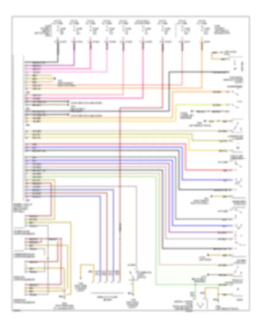
СИСТЕМА КОНДИЦИОНЕРА
Электросхема кондиционера, С Двойные Охлаждающие вентиляторы Стадии (1 из 2) для MINI Cooper 2007
Электросхема кондиционера, С Двойные Охлаждающие вентиляторы Стадии (1 из 2) для MINI Cooper 2007 - Список элементов:
- (left door)
- Air distribution motor (center console)
- Air stratification flap motor (under right side of dash center console)
- Blower motor
- Blower output stage (center of dash)
- Computer data lines system
- Fuse f30 5a
- Fuse f31 30a
- Fuse f41 5a
- Fuse holder 2 (behind left footwell trim)
- Heat exchanger sensor (behind center of dash)
- Heater blower relay
- Heating & a/c control module
- Hot at all times
- Hot in accy, run and start
- Hot in on or start
- Interior temperature sensor
- Nca
- Power steering control module fan
- Red
- Solar sensor (top of dash)
- Steering control module fan relay (left side of left footwell)
- Switch panel
- X10201
- X10205
- X10207
- X1108
- X1108 (left door)
- X13230 (under left rear seat) (convertible) (left door) (coupe)
- X1879
- X610
- X6454
Электросхема кондиционера, С Двойные Охлаждающие вентиляторы Стадии (2 из 2) для MINI Cooper 2007
Электросхема кондиционера, С Двойные Охлаждающие вентиляторы Стадии (2 из 2) для MINI Cooper 2007 - Список элементов:
- (left side of engine compt)
- A/c compressor clutch
- A/c compressor relay
- A/c pressure sensor (lower left side of engine)
- Computer data lines system
- Coolant temperature sensor (rear of engine)
- Digital motor electronics control unit (left side of engine compt)
- Electric fan 1 motor
- Electric fan relay
- Electric fan stage 2 relay
- Evaporator temperature sensor (under left side of center console)
- Fan switch second stage
- Fresh air/ recirculation flap motor (behind glove box)
- Fuse f03 15a
- Fuse f05 5a
- Fuse f07 30a
- Fuse f08 30a
- Fuse fl9 50a
- Fuse holder 3 (left side of engine compt)
- General module control unit (behind right footwell)
- Hot at all times
- Hot w/ dme main relay energized
- Nca
- Red
- X1108 (left door)
- X167
- X175 (left side of engine compt)
- X179 (convertible: below right rear seat) (coupe: right door)
- X253
- X254
- X255
- X4007
- X4010
- X4013
- X4014
- X53
- X6000
- X60004
- X8687
Электросхема кондиционера, С Одноступенчатые Охлаждающие вентиляторы (1 из 2) для MINI Cooper 2007
Электросхема кондиционера, С Одноступенчатые Охлаждающие вентиляторы (1 из 2) для MINI Cooper 2007 - Список элементов:
- (left door) x1108
- Air distribution motor (center console)
- Air stratification flap motor (under right side of dash center console)
- Blower motor
- Blower output stage (center of dash)
- Computer data lines system
- Fuse f30 5a
- Fuse f31 30a
- Fuse holder 2 (behind left footwell trim)
- Heat exchanger sensor (behind center of dash)
- Heater blower relay
- Heating & a/c control module
- Hot at all times
- Hot in accy, run and start
- Interior temperature sensor
- Nca
- Red
- Solar sensor (top of dash)
- Switch panel
- X10201
- X10205
- X10207
- X1108 (left door)
- X13230 (under left rear seat) (convertible) (left door) (coupe)
- X1879
- X610
Электросхема кондиционера, С Одноступенчатые Охлаждающие вентиляторы (2 из 2) для MINI Cooper 2007
Электросхема кондиционера, С Одноступенчатые Охлаждающие вентиляторы (2 из 2) для MINI Cooper 2007 - Список элементов:
- (left side of engine compt)
- A/c compressor clutch
- A/c compressor relay
- A/c pressure sensor (lower left side of engine)
- Computer data lines system
- Coolant temperature sensor (rear of engine)
- Digital motor electronics control unit (left side of engine compt)
- Electric fan 1 motor
- Electric fan relay
- Evaporator temperature sensor (under left side of center console)
- Fresh air/ recirculation flap motor (behind glove box)
- Fuse f03 15a
- Fuse f05 5a
- Fuse f07 30a
- Fuse f08 20a
- Fuse holder 3 (left side of engine compt)
- General module control unit (behind right footwell)
- Hot at all times
- Hot w/ dme main relay energized
- Red
- X1108 (left door)
- X167
- X175 (left side of engine compt)
- X179 (convertible: below right rear seat) (coupe: right door)
- X253
- X254
- X255
- X4010
- X4013
- X4014
- X6000
- X60004
- X8687
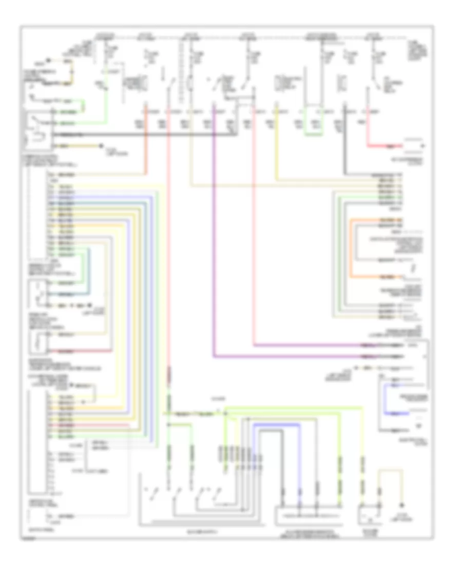
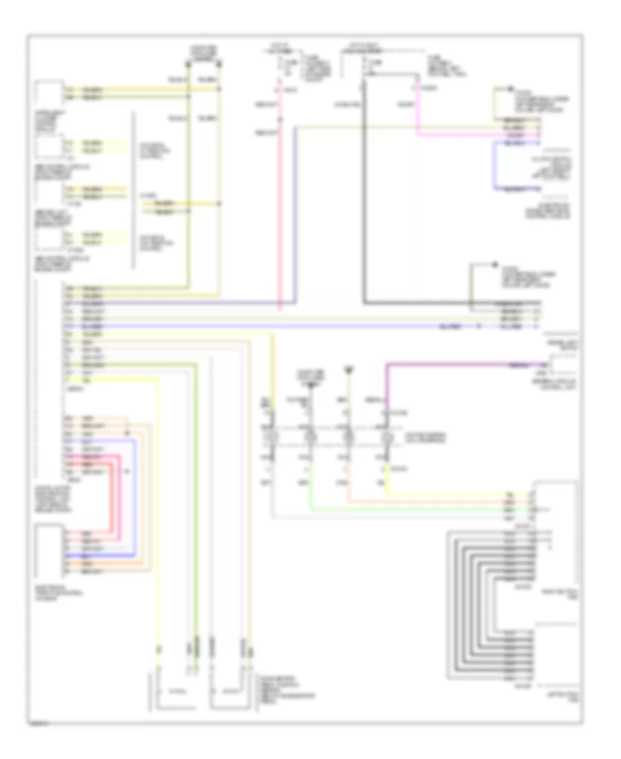
Электросхема кондиционера с ручный управлением, С Двойные Охлаждающие вентиляторы Стадии для MINI Cooper 2007
Электросхема кондиционера с ручный управлением, С Двойные Охлаждающие вентиляторы Стадии для MINI Cooper 2007 - Список элементов:
- (convertible: under left rear seat) (coupe: left door) x13230
- (left door)
- (not used)
- (or red)
- A/c compres- sor relay
- A/c compressor clutch
- A/c pressure sensor (lower left side of engine)
- Blower motor
- Blower series resistor (below left side of glove box)
- Blower switch
- Coolant temperature sensor (rear of engine)
- Digital motor electronics control unit (left side of engine compt)
- Elec- tric fan stage relay
- Electric fan 1 motor
- Electric fan relay
- Evaporator temperature sensor (under left side of center console)
- Fresh air/ recirculation flap motor (behind glove box)
- Fuse f03 15a
- Fuse f05 5a
- Fuse f07 30a
- Fuse f08 30a
- Fuse f31 30a
- Fuse f41 5a
- Fuse fl9 50a
- Fuse holder 2 (behind left footwell trim)
- Fuse holder 3 (left side of engine compt)
- General module control unit (behind right footwell)
- Heater blower relay
- Heating & a/c control panel
- Hot at all times
- Hot in on or start
- Hot w/ dme main relay energized
- Nca
- Power steering control module fan
- Red
- Second stage fan switch
- Steering control module fan relay (left side of left footwell)
- Switch panel
- W/ ihkr
- W/ ihs
- X01117
- X10201
- X10205
- X10207
- X1108
- X1108 (left door)
- X175 (left side of engine comp)
- X1879
- X253
- X255
- X4007
- X4010
- X4013
- X4014
- X53
- X6000
- X60004
- X6454
- X8687
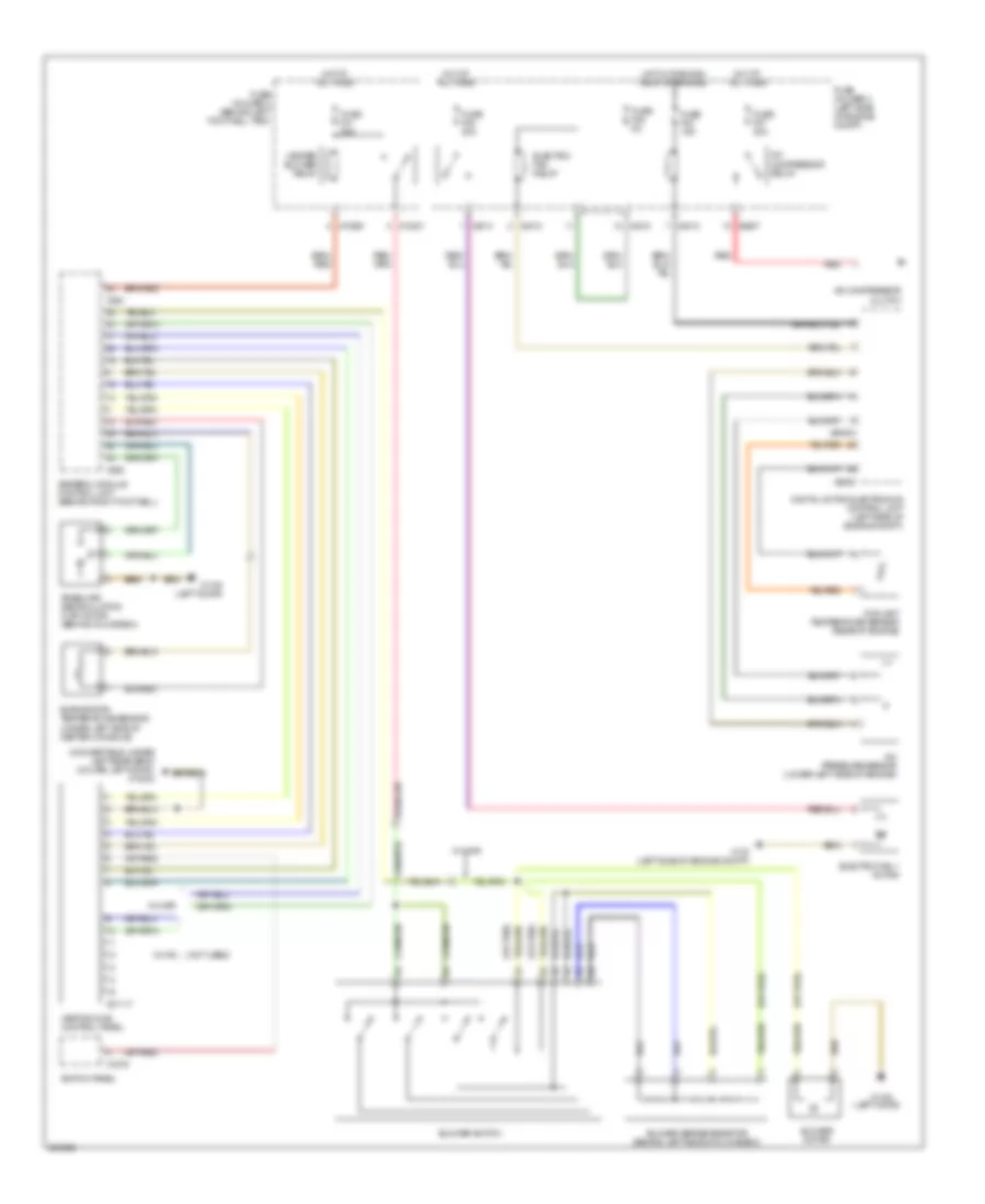
Электросхема кондиционера с ручный управлением, С Одноступенчатые Охлаждающие вентиляторы для MINI Cooper 2007
Электросхема кондиционера с ручный управлением, С Одноступенчатые Охлаждающие вентиляторы для MINI Cooper 2007 - Список элементов:
- (convertible: under left rear seat) (coupe: left door) x13230
- (left door)
- (not used)
- (or red)
- A/c compressor clutch
- A/c compressor relay
- A/c pressure sensor (lower left side of engine)
- Blower motor
- Blower series resistor (behind left side of glove box)
- Blower switch
- Coolant temperature sensor (rear of engine)
- Digital motor electronics control unit (left side of engine compt)
- Electric fan 1 motor
- Electric fan relay
- Evaporator temperature sensor (under left side of center console)
- Fresh air/ recirculation flap motor (behind glove box)
- Fuse f03 15a
- Fuse f05 5a
- Fuse f07 30a
- Fuse f08 20a
- Fuse f31 30a
- Fuse holder 2 (behind left footwell trim)
- Fuse holder 3 (left side of engine compt)
- General module control unit (behind right footwell)
- Heater blower relay
- Heating & a/c control panel
- Hot at all times
- Hot w/ dme main relay energized
- Red
- Switch panel
- W/ ihkr
- W/ ihs
- X01117
- X10201
- X10205
- X1108
- X1108 (left door)
- X175 (left side of engine compt)
- X1879
- X253
- X255
- X4010
- X4013
- X4014
- X6000
- X60004
- X8687
СИСТЕМА КРУИЗКОНТРОЛЯ
Электросхема системы круизконтроля для MINI Cooper 2007
Электросхема системы круизконтроля для MINI Cooper 2007 - Список элементов:
- Abs control module (right rear of engine compt)
- Abs/dsc unit (right rear of engine compt)
- Accelerator pedal position sensor (below accelerator pedal)
- Brake light switch
- Clutch switch module (left side of left footwell)
- Computer data lines system
- Contact spring (volute spring)
- Digital motor electronics control unit (left side of engine compt)
- Electronic immobilizer (ews) control module
- Electronic throttle control housing
- Fuse 5a
- Fuse holder 2 (behind left footwell trim)
- Fuse holder 3 (left side of engine compt)
- General module control unit
- Hot at all times
- Hot in accy, run and start
- Instrument cluster control module
- Left button pad
- Nca
- Red
- Right button pad
- W/ dsc
- W/o dsc & w/ traction control
- W/o dsc & w/o traction control
- X01000
- X01001
- X01002
- X01003
- X10195
- X10200
- X11
- X11525
- X13230 (convertible: under left rear seat) (coupe: left door)
- X151
- X1746
- X255
- X4013
- X6000
- X60004
СИСТЕМА ОХЛАЖДЕНИЯ
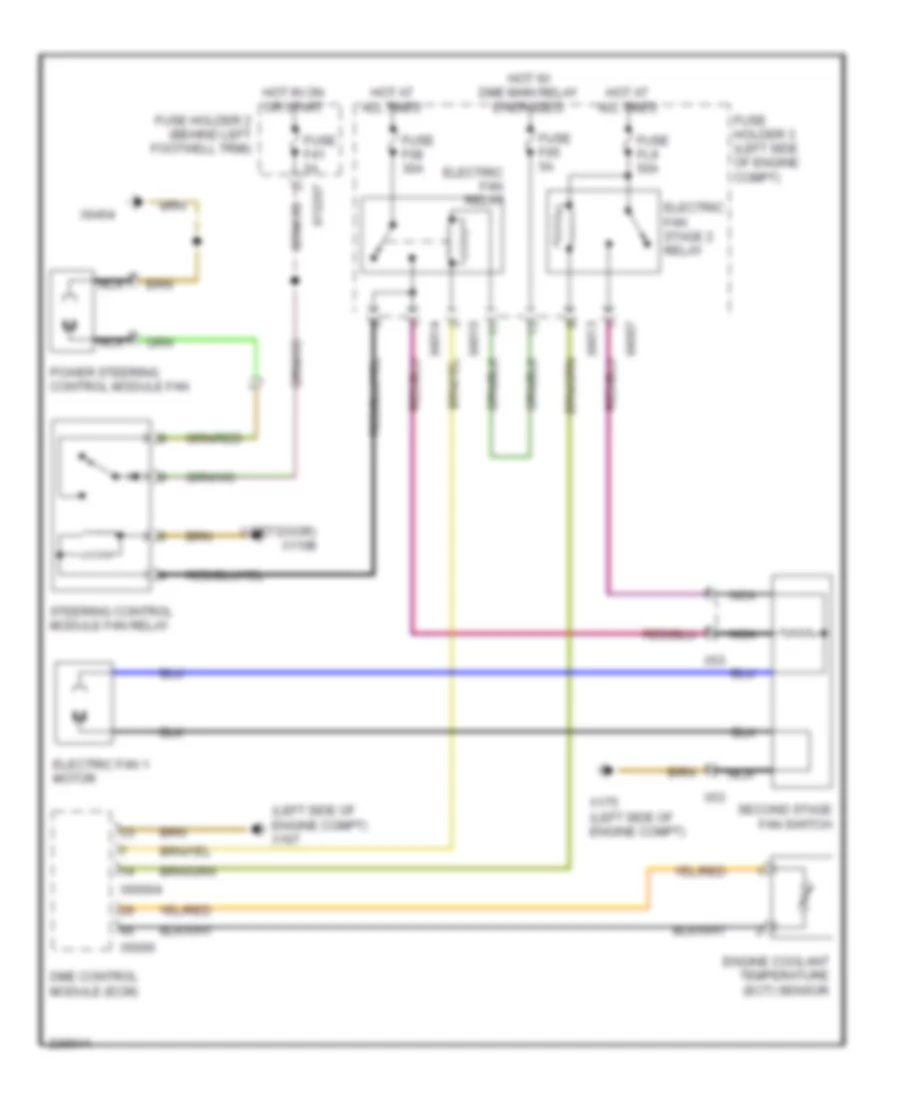
Электросхема системы охлаждения, двойная стадия для MINI Cooper 2007
Электросхема системы охлаждения, двойная стадия для MINI Cooper 2007 - Список элементов:
- (left door) x1108
- (left side of engine compt) x167
- Dme control module (ecm)
- Electric fan 1 motor
- Electric fan relay
- Electric fan stage 2 relay
- Engine coolant temperature (ect) sensor
- Fuse f05 5a
- Fuse f08 30a
- Fuse f41 5a
- Fuse fl9 50a
- Fuse holder 2 (behind left footwell trim)
- Fuse holder 3 (left side of engine compt)
- Hot at all times
- Hot in on or start
- Hot w/ dme main relay energized
- Nca
- Power steering control module fan
- Second stage fan switch
- Steering control module fan relay
- X10207
- X175 (left side of engine compt)
- X4007
- X4010
- X4013
- X4014
- X53
- X6000
- X60004
- X6454
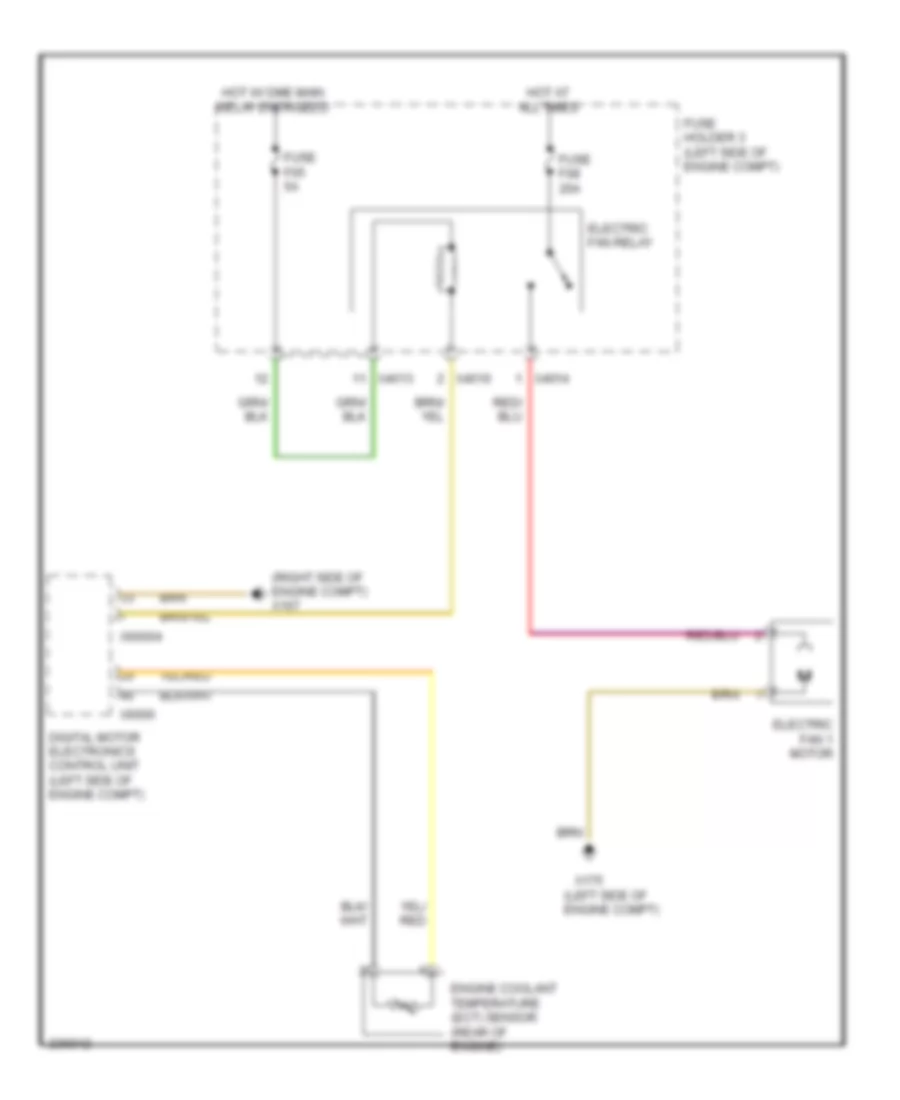
Электросхема системы охлаждения, одноступенчатая для MINI Cooper 2007
Электросхема системы охлаждения, одноступенчатая для MINI Cooper 2007 - Список элементов:
- (left side of engine compt)
- (right side of engine compt) x167
- Digital motor electronics control unit (left side of engine compt)
- Electric fan 1 motor
- Electric fan relay
- Engine coolant temperature (ect) sensor (rear of engine)
- Fuse f05 5a
- Fuse f08 20a
- Fuse holder 3 (left side of engine compt)
- Hot at all times
- Hot w/ dme main relay energized
- X175
- X4010
- X4013
- X4014
- X6000
- X60004
СИСТЕМА ПЕРЕДАЧИ ДАННЫХ
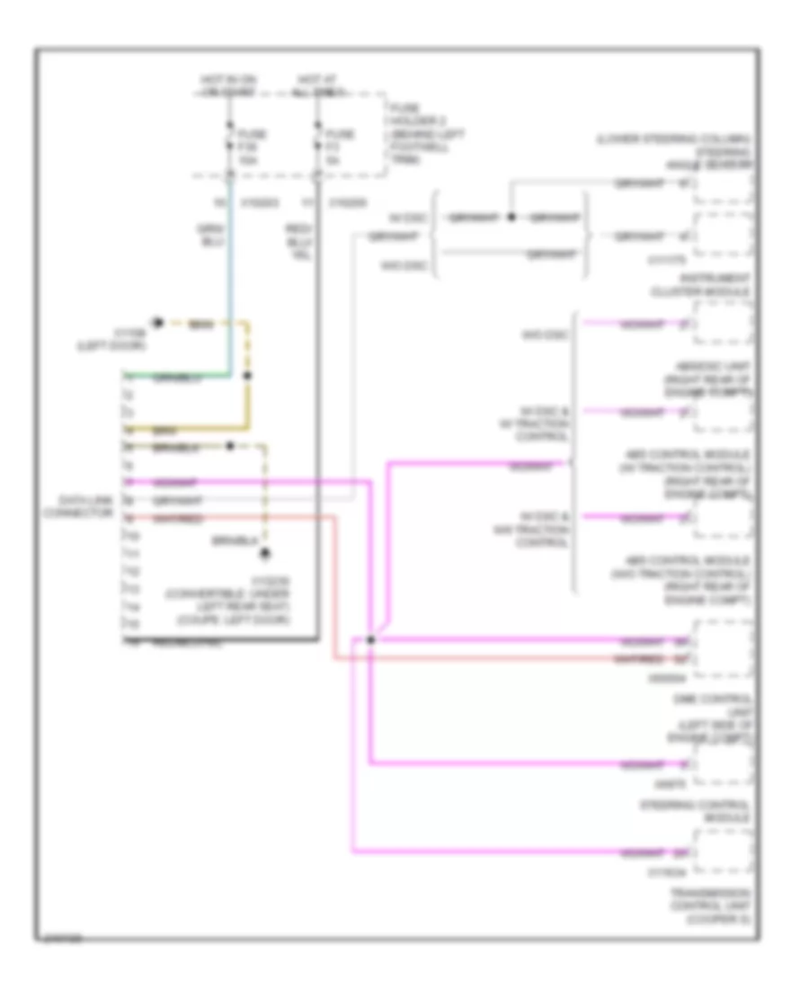
схема соединителя канала связи для MINI Cooper 2007
схема соединителя канала связи для MINI Cooper 2007 - Список элементов:
- (lower steering column) steering angle sensor
- Abs control module (w/ traction control) (right rear of engine compt)
- Abs control module (w/o traction control) (right rear of engine compt)
- Abs/dsc unit (right rear of engine compt)
- Connector
- Data link
- Dme control unit (left side of engine compt)
- Fuse f3 5a
- Fuse f36 10a
- Fuse holder 2 (behind left footwell trim)
- Hot at all times
- Hot in on or start
- Instrument cluster module
- Steering control module
- Transmission control unit (cooper s)
- W/ dsc
- W/ dsc & w/ traction control
- W/ dsc & w/0 traction control
- W/o dsc
- X10200
- X10203
- X1108 (left door)
- X11175
- X11634
- X13230 (convertible: under left rear seat) (coupe: left door)
- X60004
- X6975
высокая/Низкая Автобусная Схема для MINI Cooper 2007
высокая/Низкая Автобусная Схема для MINI Cooper 2007 - Список элементов:
- Abs control module (w/ traction control) (right rear of engine compt)
- Abs control unit (w/o traction control) (right rear of engine compt)
- Abs/dsc unit (right rear of engine compt)
- Amplifier
- Auxiliary
- Boost radio
- Cd changer
- Cluster
- Contact spring (volute spring)
- Convertible soft top control module
- Cooper s
- Digital motor electronics control unit (left side of engine compt)
- Eject box
- Electronic immobilizer control unit (left side of dash)
- Except cooper s
- General module (behind right footwell)
- Instrument
- Instrument cluster module
- Multiple restraint system control unit (center tunnel, under carpet)
- Navigation computer
- Nca
- On-board monitor
- Park distance control unit (convt: right rear passenger compt) (coupe: right rear of luggage compt)
- Radio control module
- Rain sensor (windshield top)
- Steering angle sensor (w/ dsc) (lower steering column)
- Sunroof module control unit (under front headliner)
- Transmission control unit (left side of left footwell)
- Universal electronic charging & hands-free module (ulf)
- Video control module
- W/ dsc
- W/ ihka
- W/ telephone provisions
- W/ universal electronic charging & hands-free module (ulf)
- W/o dsc & w/ traction control
- W/o dsc & w/o traction control
- Wave radio
- X11
- X11175
- X11176
- X11177
- X11525
- X11633
- X1312
- X14133
- X1746
- X18114
- X19561
- X254
- X255
- X4545
- X60004
СИСТЕМА УПРАВЛЕНИЯ ДВИГАТЕЛЯ
1.6L
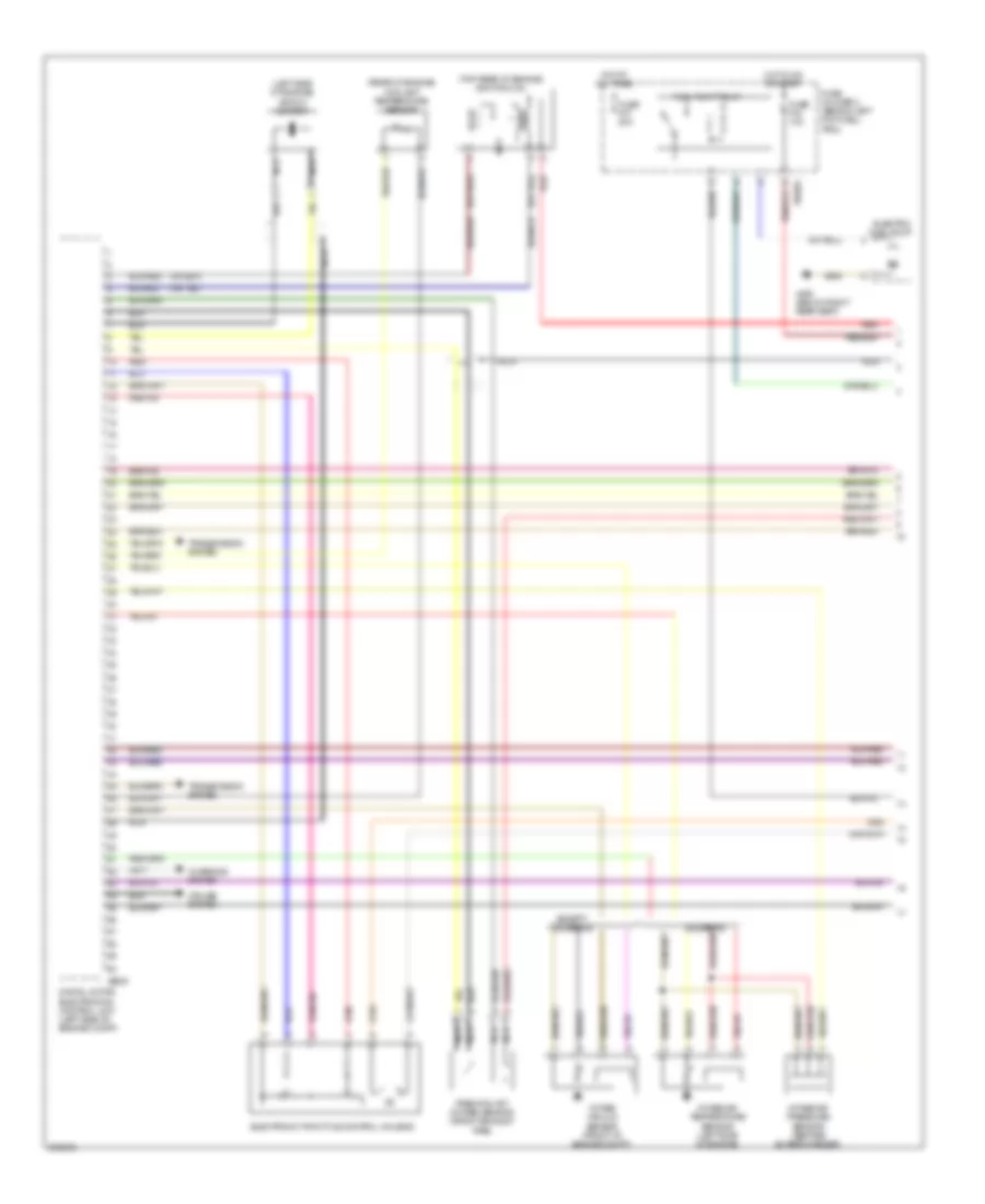
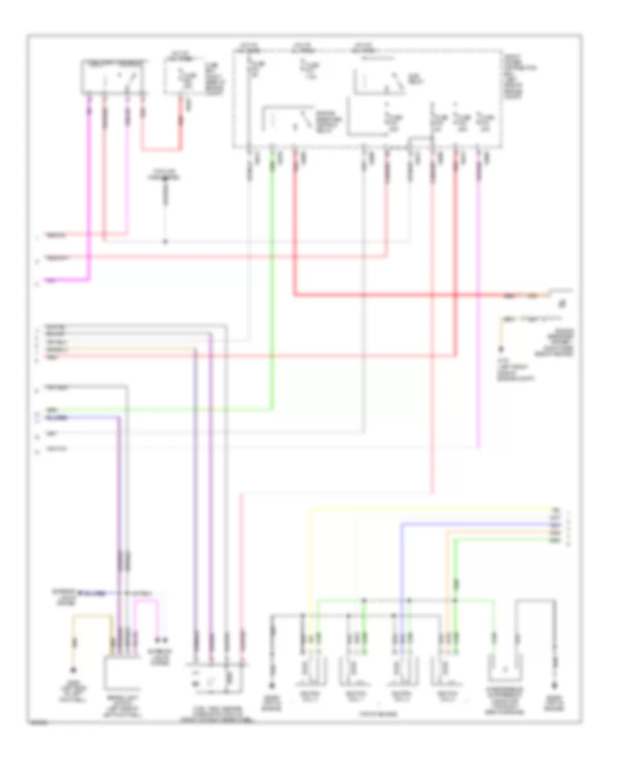
1.6L, Электросхема системы управления двигателем (1 из 3) для MINI Cooper 2007
1.6L, Электросхема системы управления двигателем (1 из 3) для MINI Cooper 2007 - Список элементов:
- (left side of engine) knock sensor
- (rear of engine) coolant temperature sensor
- (top rear of engine) ignition coil
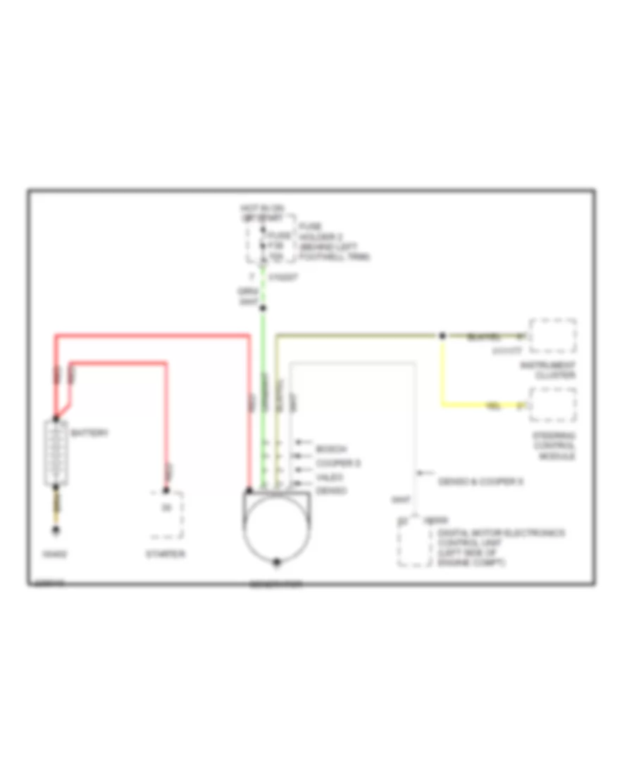
- Charging system
- Cooper s
- Cruise system
- Digital motor electronics control unit (left side of engine compt)
- Electric fuel pump
- Electronic throttle control housing
- Except cooper s
- Fuel pump relay
- Fuse f34 10a
- Fuse f37 20a
- Fuse holder 2 (behind left footwell trim)
- Hot at all times
- Hot in on or start
- Intake air pressure sensor (before supercharger)
- Intake air temperature sensor (left side of engine)
- Intake vacuum sensor (front of engine compt)
- Nca
- Precatalyst oxygen sensor (front exhaust pipe)
- Red
- Transmission system
- X10204
- X490 (below right rear seat)
- X6000
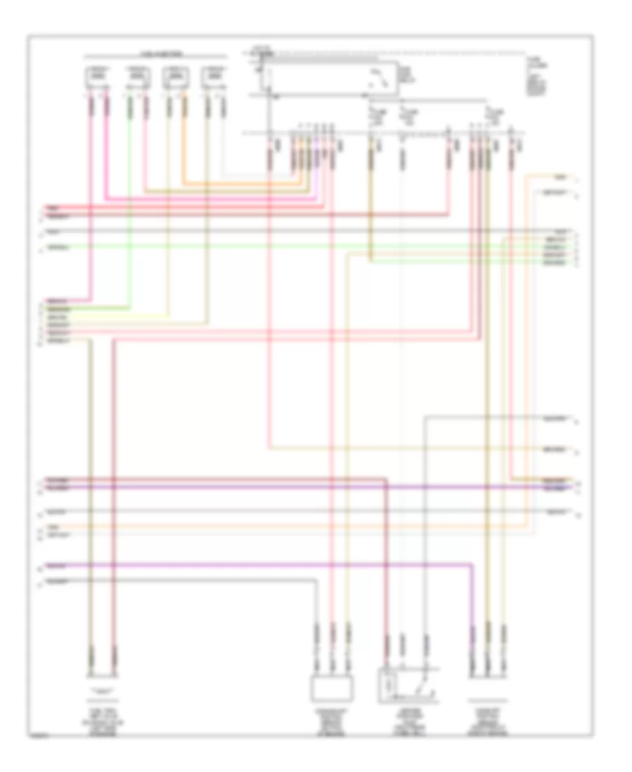
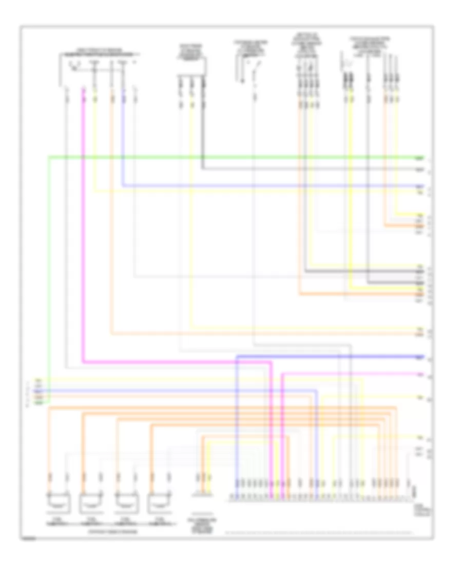
1.6L, Электросхема системы управления двигателем (2 из 3) для MINI Cooper 2007
1.6L, Электросхема системы управления двигателем (2 из 3) для MINI Cooper 2007 - Список элементов:
- Camshaft position sensor (right front side of engine)
- Crankshaft position sensor (bottom of engine)
- Cyl 1
- Cyl 2
- Cyl 3
- Cyl 4
- Dme main relay
- Fuel injectors
- Fuel tank vent valve solenoid valve (left side of engine)
- Fuse f02 20a
- Fuse f03 15a
- Fuse f04 15a
- Fuse holder (left side of engine compt)
- Hot at all times
- Leakage diagnosis pump (right rear wheelwell)
- Nca
- Red
- X4009
- X4013
- X8687
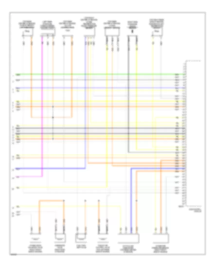
1.6L, Электросхема системы управления двигателем (3 из 3) для MINI Cooper 2007
1.6L, Электросхема системы управления двигателем (3 из 3) для MINI Cooper 2007 - Список элементов:
- (convertible: under left rear seat) (coupe: left door) x13230
- (left side of left footwell) clutch switch
- Accelerator pedal position sensor (right side of left footwell)
- Air conditioning system
- Anti-theft system
- Brake light switch (left side of left footwell)
- Catalyst oxygen sensor (front exhaust pipe)
- Computer data lines system
- Contact spring (volute spring)
- Cruise control system
- Digital motor electronics control unit (left side of engine compt)
- Exterior lights system
- Fuse f01 5a
- Fuse f6 5a
- Fuse holder 2 (behind left footwell trim)
- Fuse holder 3 (left side of engine compt)
- Hot at all times
- Hot in acc, run or start
- Nca
- Power tops system
- Shift interlock system
- X10200
- X13230 (under left rear seat) (convt) (left door) (coupe)
- X167 (left side of engine compt)
- X4013
- X6000
- X6004
- X6454
1.6L ТУРБО
1.6L турбо, Электросхема системы управления двигателем (1 из 4) для MINI Cooper 2007
1.6L турбо, Электросхема системы управления двигателем (1 из 4) для MINI Cooper 2007 - Список элементов:
- Accelerator pedal module (part of acceleration pedal assembly)
- Anti-theft system
- Brake vacuum sensor
- Clutch module (under left side of dash)
- Computer data lines system
- Coolant pressure sensor
- Cooling fans system
- Dme control module
- Electric fuel pump
- Front power distribution box (left side of engine compt)
- Fuel pump relay
- Fuse f010 15a
- Fuse f43 20a
- Hot at all times
- Hot w/ terminal 30g relay energized
- Junction box (right side of right footwell)
- Neutral sensor (left rear of engine)
- Power saving relay
- Red
- Starting/ charging system
- Starting/charging system
- W/ automatic engine start-stop function
- X11002
- X11008
- X11010
- X13795 (behind left rear trim panel)
- X167
- X2042 (left side of left footwell)
- X4010
- X4014
- X60004
1.6L турбо, Электросхема системы управления двигателем (2 из 4) для MINI Cooper 2007
1.6L турбо, Электросхема системы управления двигателем (2 из 4) для MINI Cooper 2007 - Список элементов:
- (left front side of engine compt)
- (top of engine)
- Brake light switch (left side of left footwell)
- Cooling fans system
- Dme relay
- Engine breather heater 1 (right rear side of engine)
- Engine breather heating relay
- Exterior lights system
- Front power distribution box (left side of engine compt)
- Fuel injectors relay
- Fuel tank leakage diagnostic module (front of right rear wheel)
- Fuse box (right rear of engine compt)
- Fuse f01 5a
- Fuse f02 25a
- Fuse f03 20a
- Fuse f04 20a
- Fuse f05 5a
- Fuse f07 7.5a
- Fuse f68 40a
- Hot at all times
- Ignition coil 1
- Ignition coil 2
- Ignition coil 3
- Ignition coil 4
- Interference suppression capacitor (top right side of engine)
- Red
- X175
- X2042 (left side of left footwell)
- X4009
- X4010
- X4013
- X6401
- X64561 (top of engine)
1.6L турбо, Электросхема системы управления двигателем (3 из 4) для MINI Cooper 2007
1.6L турбо, Электросхема системы управления двигателем (3 из 4) для MINI Cooper 2007 - Список элементов:
- (bottom of exhaust pipe) oxygen sensor (behind catalytic converter)
- (right front of engine) electric throttle valve actuator
- (right rear of engine) crankshaft sensor
- (top of exhaust pipe) oxygen sensor (before catalytic converter)
- (top rear center of engine) oil pressure switch
- (top right side of engine)
- Dme control module
- Fuel injection 1
- Fuel injection 2
- Fuel injection 3
- Fuel injection 4
- Nca
- Rail pressure sensor (right side of engine)
- X60232
1.6L турбо, Электросхема системы управления двигателем (4 из 4) для MINI Cooper 2007
1.6L турбо, Электросхема системы управления двигателем (4 из 4) для MINI Cooper 2007 - Список элементов:
- (left rear of engine) turbocharger coolant pump
- (right side of engine) knock sensor
- (top front center of engine) intake temperature boost pressure sensor
- (top rear center of engine)
- (top rear center of engine) characteristic map thermostat
- (top rear center of engine) volume control valve
- (top right rear side of engine) engine coolant temperature sensor
- Dme control module
- Fuel tank vent valve
- Hot-film air mass meter (top rear center of engine)
- Intake camshaft sensor
- Intake pipe pressure sensor (right front side of engine)
- Intake vanos solenoid valve (right front side of engine)
- Nca
- Thrust air control valve (top left rear side of engine)
- Wastegate valve (right side of engine)
- X60231
СИСТЕМА УСИЛИТЕЛЯ РУЛЯ
Электросхема усилителя руля для MINI Cooper 2007
Электросхема усилителя руля для MINI Cooper 2007 - Список элементов:
- Abs control module (w/ traction control) (right rear of engine compt)
- Abs control module (w/o traction control) (right rear of engine compt)
- Abs/dsc control module (right rear of engine compt)
- Data link connector
- Digital motor electronics control unit (left side of engine compt)
- Fuse f39 5a
- Fuse fl4 100a
- Fuse holder 2 (behind left footwell trim)
- Fuse holder 3 (left side of engine compt)
- Hot at all times
- Hot in on or start
- Red
- Starting/charging system
- Steering control unit/ hydraulic pump (lower left side of engine)
- Transmission control unit (left side of left footwell) (cooper s)
- W/ dsc
- W/o dsc w/ traction control
- W/o dsc w/o traction control
- X01123
- X10207
- X11
- X11525
- X11634
- X13441
- X173 (behind battery)
- X1746
- X60004
- X6975
Система Фар
Электросхема фар для MINI Cooper 2007
Электросхема фар для MINI Cooper 2007 - Список элементов:
- (convertible: under left rear seat) (coupe: left door)
- (left door) x1108
- (left side of engine compt)
- (right rear side of luggage compt)
- (right side of engine compt)
- (right side of engine compt) x165
- (right side of right footwell)
- (right side of right footwell) x151
- All times
- Computer data lines system
- Front fog light relay
- Fuse f010 15a
- Fuse f40 5a
- Fuse f8 5a
- Fuse fl12 50a
- Fuse fl8 50a
- Fuse holder 2 (behind left footwell trim)
- Fuse holder 3 (left side of engine compt)
- General module control unit (behind right footwell)
- High beam
- Hot at
- Hot at all times
- Hot in accy,
- Hot in on or start
- Instrument cluster module
- Left fog light
- Left headlight
- Left xenon headlight ignition trigger
- Low beam
- Rear fog light
- Red
- Right fog light
- Right headlight
- Right xenon headlight ignition trigger
- Run and start
- Switch panel
- Turn signal/ headlight dimmer switch
- W/ halogen headlight
- W/ xenon headlight
- X10200
- X10207
- X11175
- X11177
- X13230
- X151
- X165
- X175
- X254
- X255
- X332
- X4009
- X4010
- X4013
- X4014
- X494
Электросхема корректора фар для MINI Cooper 2007
Электросхема корректора фар для MINI Cooper 2007 - Список элементов:
- (right side of right footwell)
- Brake light switch
- Computer data lines system
- Digital motor electronics control unit (left side of eng compt)
- Exterior lights system
- Fuse f19 30a
- Fuse holder 2 (behind left footwell trim)
- General module control unit (behind right footwell)
- Headlight vertical aim front load sensor (on front left axle carrier)
- Headlight vertical aim rear load sensor (on rear left axle carrier)
- Hot at all times
- Left headlight
- Right headlight
- X10202
- X151
- X179 (convertible: below right rear seat) (coupe: right door)
- X253
- X254
- X255
- X332
- X60004
СИСТЕМЫ СИДЕНИЙ
Электросхема подогрева сидений для MINI Cooper 2007
Электросхема подогрева сидений для MINI Cooper 2007 - Список элементов:
- (right side of right footwell)
- Acc
- Driver's backrest heating
- Driver's seat heating
- Driver's seat heating switch
- Fuse f12 20a
- Fuse holder 2 (behind left footwell trim)
- Hot in run or start
- Ignition switch
- Interior lights system
- Lock
- Nca
- Off
- Passenger's backrest heating
- Passenger's seat heating
- Passenger's seat heating switch
- Run
- Start
- X10206
- X151
- X151 (right side of right footwell)
- X33
Стартер Генератор
Электросхема Генератора для MINI Cooper 2007
Электросхема Генератора для MINI Cooper 2007 - Список элементов:
- Battery
- Bosch
- Cooper s
- Denso
- Denso & cooper s
- Digital motor electronics control unit (left side of engine compt)
- Fuse f38 10a
- Fuse holder 2 (behind left footwell trim)
- Generator
- Hot in on or start
- Instrument cluster
- Red
- Starter
- Steering control module
- Valeo
- X10207
- X11177
- X6000
- X6402
Электросхема стартера для MINI Cooper 2007
Электросхема стартера для MINI Cooper 2007 - Список элементов:
- Acc
- Battery
- Electronic immobilizer control unit (left side of dash)
- Fuse fl7 50a
- Fuse holder 3 (left side of engine compt)
- Generator
- Hot at all times
- Ignition switch
- Lock
- Off
- Red
- Run
- Start
- Starter
- X4010
- X6402
Стеклоочистители и Стеклоомыватели Дворники
Электросхема передних стеклоочистителей дворников и омывателя лобового стекла, Кабриолет для MINI Cooper 2007
Электросхема передних стеклоочистителей дворников и омывателя лобового стекла, Кабриолет для MINI Cooper 2007 - Список элементов:
- (left side of engine compt)
- Computer data lines system
- Fast/ slow wiper motor relay
- Front washer pump relay
- Fuse f09 20a
- Fuse f11 5a
- Fuse f23 20a
- Fuse f7 5a
- Fuse holder 2 (behind left footwell trim)
- Fuse holder 3 (left side of engine compt)
- General module control unit (behind right footwell)
- Hot at all times
- Hot in accy,
- Hot in on or start
- Rain sensor (windshield top)
- Run and start
- Washer fluid level switch
- Washer pump
- Wiper motor
- Wiper motor relay
- Wiper/washer switch
- X10200
- X10207
- X1108 (left door)
- X13230 (under left rear seat)
- X165 (right side of engine compt)
- X175
- X253
- X254
- X255
- X332
- X4009
- X4010
- X4013
Электросхема передних стеклоочистителей дворников и омывателя лобового стекла, Кабриолет Except для MINI Cooper 2007
Электросхема передних стеклоочистителей дворников и омывателя лобового стекла, Кабриолет Except для MINI Cooper 2007 - Список элементов:
- (left side of engine compt)
- Computer data lines system
- Fast/ slow wiper motor relay
- Front washer pump relay
- Fuse f09 20a
- Fuse f11 5a
- Fuse f23 20a
- Fuse f7 5a
- Fuse holder 2 (behind left footwell trim)
- Fuse holder 3 (left side of engine compt)
- General module control unit (behind right footwell)
- Hot at all times
- Hot in acc,
- Hot in on or start
- Rain sensor (windshield top)
- Rear washer pump relay
- Run and start
- Washer fluid level switch
- Washer pump
- Wiper motor
- Wiper motor relay
- Wiper/washer switch
- X10200
- X10207
- X1108 (left door)
- X13230 (left door)
- X165 (right side of engine compt)
- X175
- X253
- X254
- X255
- X332
- X4009
- X4010
- X4013
схема шайбы фары для MINI Cooper 2007
схема шайбы фары для MINI Cooper 2007 - Список элементов:
- Fuse f14 10a
- Fuse f19 30a
- Fuse f25 30a
- Fuse holder 2 (behind left footwell trim)
- General module control unit (behind right footwell)
- Headlight washer module
- Headlight washer pump
- Hot at all times
- Wash
- Wiper/washer switch
- X10202
- X10205
- X10206
- X13230 (convertible: under left rear seat) (coupe: left door)
- X151 (right side of right footwell)
- X175 (left side of engine compt)
- X254
- X255
- X332
Электросхема заднего стеклоочистителя дворника и омывателя для MINI Cooper 2007
Электросхема заднего стеклоочистителя дворника и омывателя для MINI Cooper 2007 - Список элементов:
- (left door)
- Front washer pump relay
- Fuse f11 5a
- Fuse f17 15a
- Fuse f23 20a
- Fuse holder 2 (behind left footwell trim)
- General module control unit (behind right footwell)
- Hot at all times
- Hot in on or start
- Rear washer pump relay
- Rear window wiper motor (on liftgate)
- Rear wiper motor relay
- Washer fluid level switch
- Window washer pump
- Wiper/washer switch
- X10204
- X10207
- X1108
- X1108 (left door)
- X13230 (left door)
- X165 (right side of engine compt)
- X253
- X254
- X255
- X332
Электросхема быстрого подогрева шайбы для MINI Cooper 2007
Электросхема быстрого подогрева шайбы для MINI Cooper 2007 - Список элементов:
- (convertible: under left rear seat) (coupe: left door) x13230
- (left side of left footwell) clutch switch
- Accelerator pedal position sensor (right side of left footwell)
- Air conditioning system
- Anti-theft system
- Brake light switch (left side of left footwell)
- Catalyst oxygen sensor (front exhaust pipe)
- Computer data lines system
- Contact spring (volute spring)
- Cruise control system
- Digital motor electronics control unit (left side of engine compt)
- Exterior lights system
- Fuse f01 5a
- Fuse f6 5a
- Fuse holder 2 (behind left footwell trim)
- Fuse holder 3 (left side of engine compt)
- Hot at all times
- Hot in acc, run or start
- Nca
- Power tops system
- Shift interlock system
- X10200
- X13230 (under left rear seat) (convt) (left door) (coupe)
- X167 (left side of engine compt)
- X4013
- X6000
- X6004
- X6454
ЦЕНТРАЛЬНЫЙ ЗАМОК
Электросхема центрального замка, Кабриолет для MINI Cooper 2007
Электросхема центрального замка, Кабриолет для MINI Cooper 2007 - Список элементов:
- (left door) x1108
- (left rear of trunk)
- (right side of engine compt)
- Central locking drive, trunk lid/tailgate (center rear of trunk)
- Computer data lines system
- Diode
- Driver's door lock
- Driver's door microwave sensor
- Fuel filler door lock
- Fuse f1 30a
- Fuse f14 10a
- Fuse f19 30a
- Fuse f23 20a
- Fuse f24 5a
- Fuse f4 5a
- Fuse f7 5a
- Fuse fl 12 50a
- Fuse fl 8 50a
- Fuse holder 2 (behind left footwell trim)
- Fuse holder 3 (left side of engine compt)
- General module control unit (behind right footwell)
- Hot at all times
- Hot in accy, run and start
- License plate lights
- Not used
- Passenger's door lock
- Passenger's door microwave sensor
- Rear left microwave sensor
- Rear right microwave sensor
- Red
- Siren w/ tilt alarm sensor
- Switch panel
- Theft ind
- Trunk lid contact switch
- Turn signal/ headlight dimmer switch
- Underhood light switch
- X10200
- X10201
- X10202
- X10206
- X10207
- X1108 (left door)
- X13230 (under left rear seat)
- X151 (right side of right footwell)
- X165
- X165 (right side of engine compt)
- X179 (below right rear seat)
- X253
- X254
- X255
- X332
- X4009
- X4010
- X490
- X490 (left rear of trunk)
- X494 (right rear side of luggage compt)
Электросхема центрального замка, Кабриолет Except для MINI Cooper 2007
Электросхема центрального замка, Кабриолет Except для MINI Cooper 2007 - Список элементов:
- (left door) x1108
- (left rear side of luggage compt)
- (not used)
- (right side of engine compt)
- Central locking drive, trunk lid/tailgate
- Central locking remote control (under front headliner)
- Computer data lines system
- Driver's door lock
- Fuel filler door lock
- Fuse f1 30a
- Fuse f14 10a
- Fuse f19 30a
- Fuse f23 20a
- Fuse f24 5a
- Fuse f4 5a
- Fuse f7 5a
- Fuse fl 12 50a
- Fuse fl 8 50a
- Fuse holder 2 (behind left footwell trim)
- Fuse holder 3 (left side of engine compt)
- General module control unit (behind right footwell)
- Hot at all times
- Hot in accy, run and start
- Interior protection 1 control module (in headliner)
- License plate lights
- Passenger's door lock
- Power distribution system
- Red
- Siren w/ tilt sensor
- Switch panel
- Theft ind
- Turn signal/ headlight dimmer switch
- Underhood light switch
- X10200
- X10201
- X10202
- X10206
- X10207
- X1108 (left door)
- X13230 (left door)
- X151 (right side of right footwell)
- X165
- X165 (right side of engine compt)
- X179 (right door)
- X253
- X254
- X255
- X332
- X4009
- X4010
- X490
- X494 (right rear side of luggage compt)

 Čeština
 Dansk
Dansk Deutsch
 Ελληνικά
 English
 English
 Suomi
Suomi Français
 Français
 עברית
עברית Hrvatski
 Magyar
 Italiano
 日本語
日本語 한국어
한국어 Nederlands
 Polski
 Português
 Português
 Română
 Русский
 Slovenčina
 Slovenščina
 Svenska
 Türkçe
 中文 (中国)