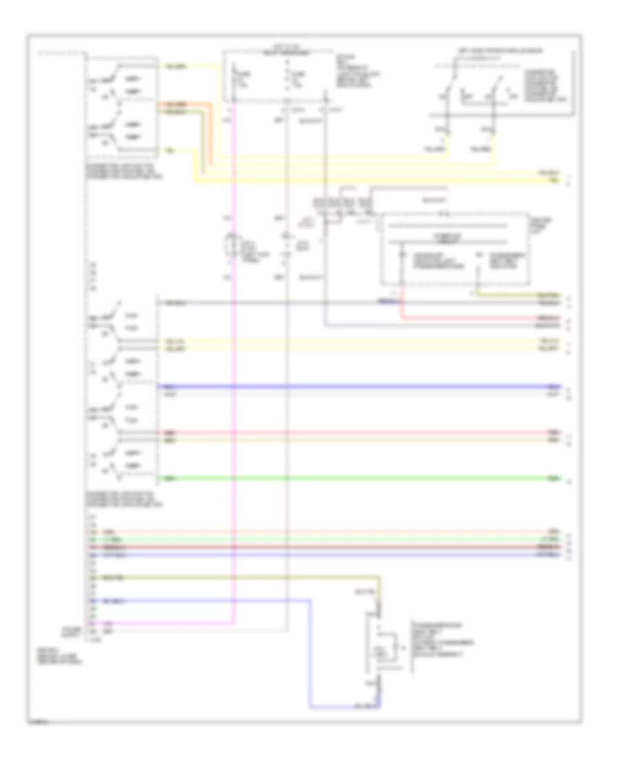
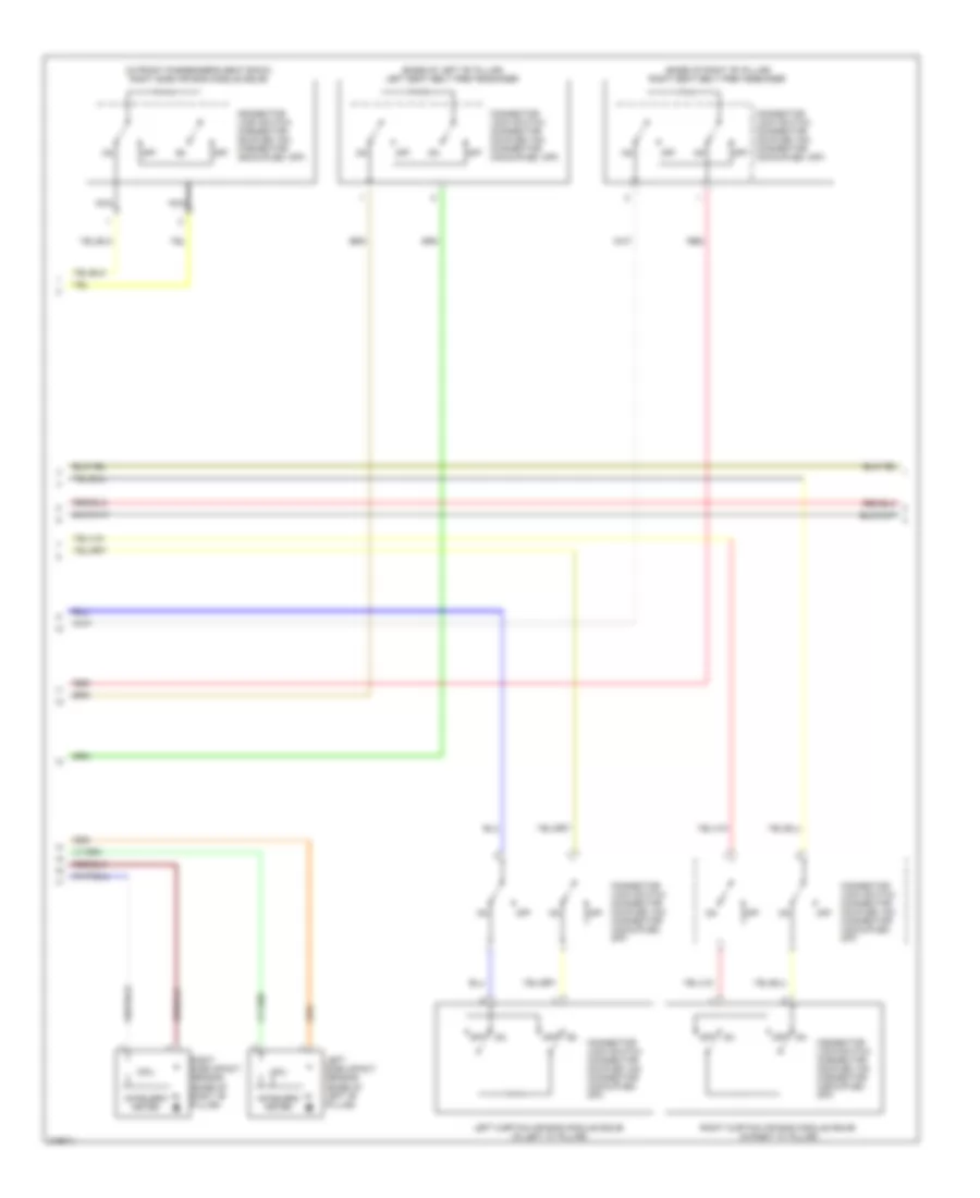
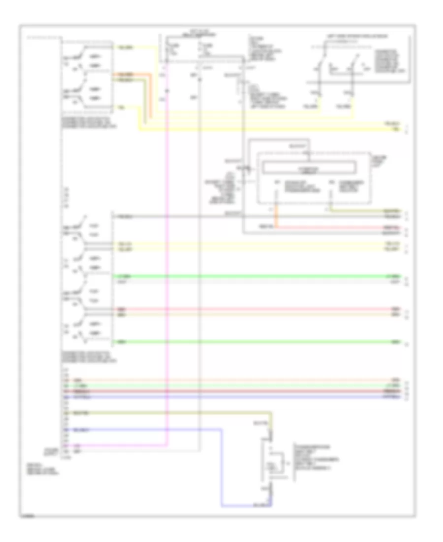
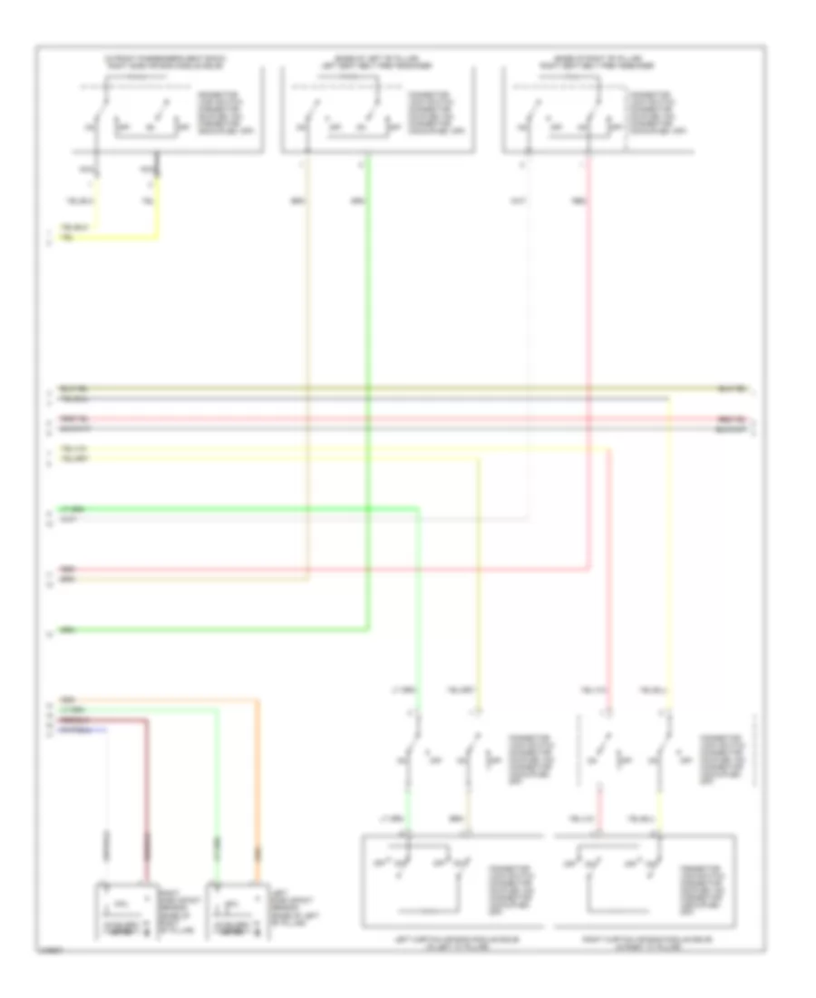
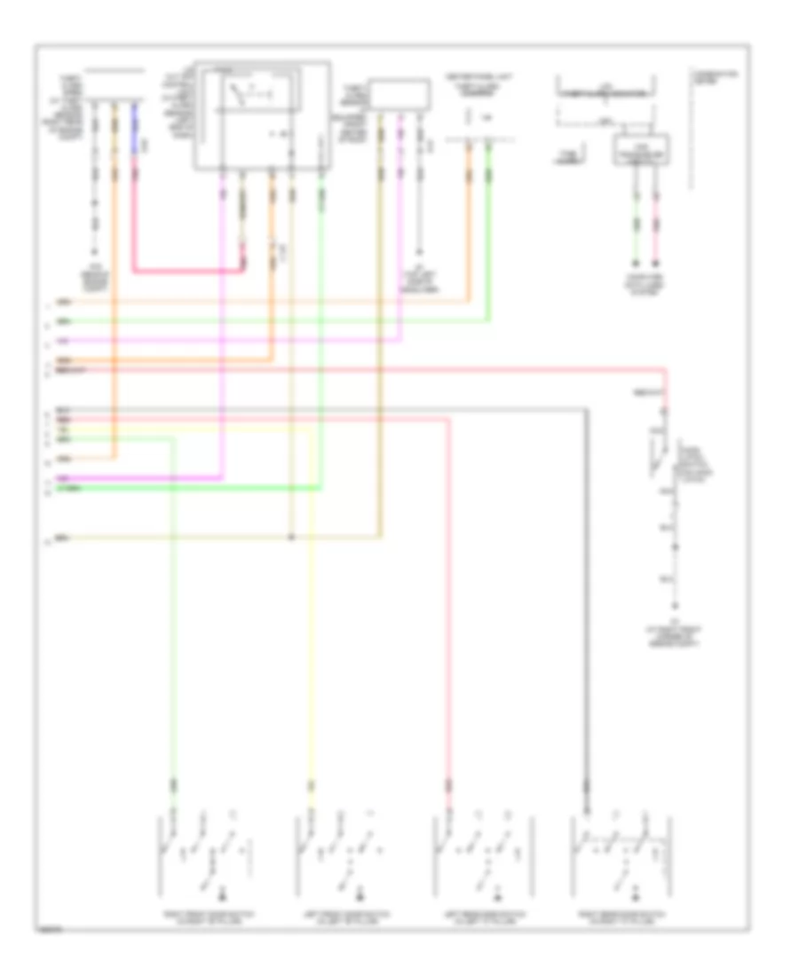
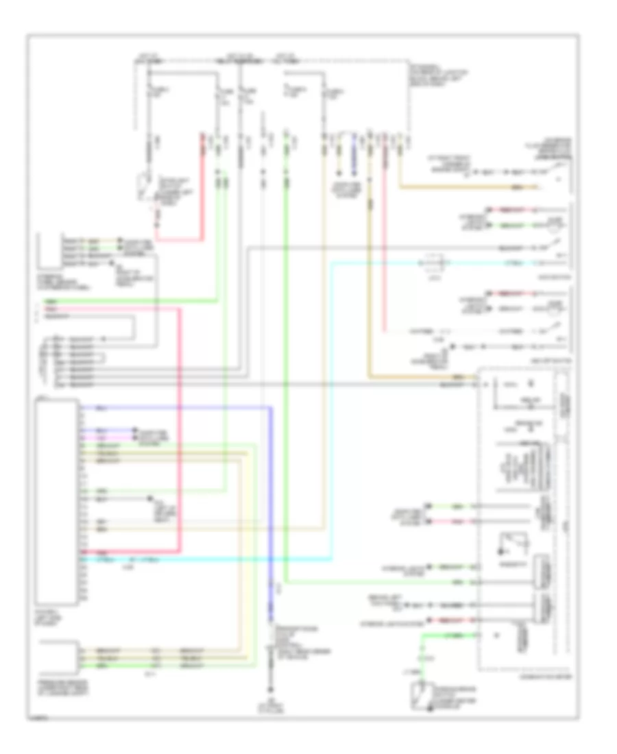
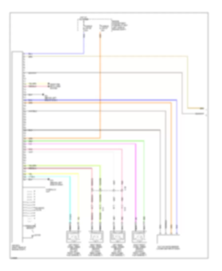
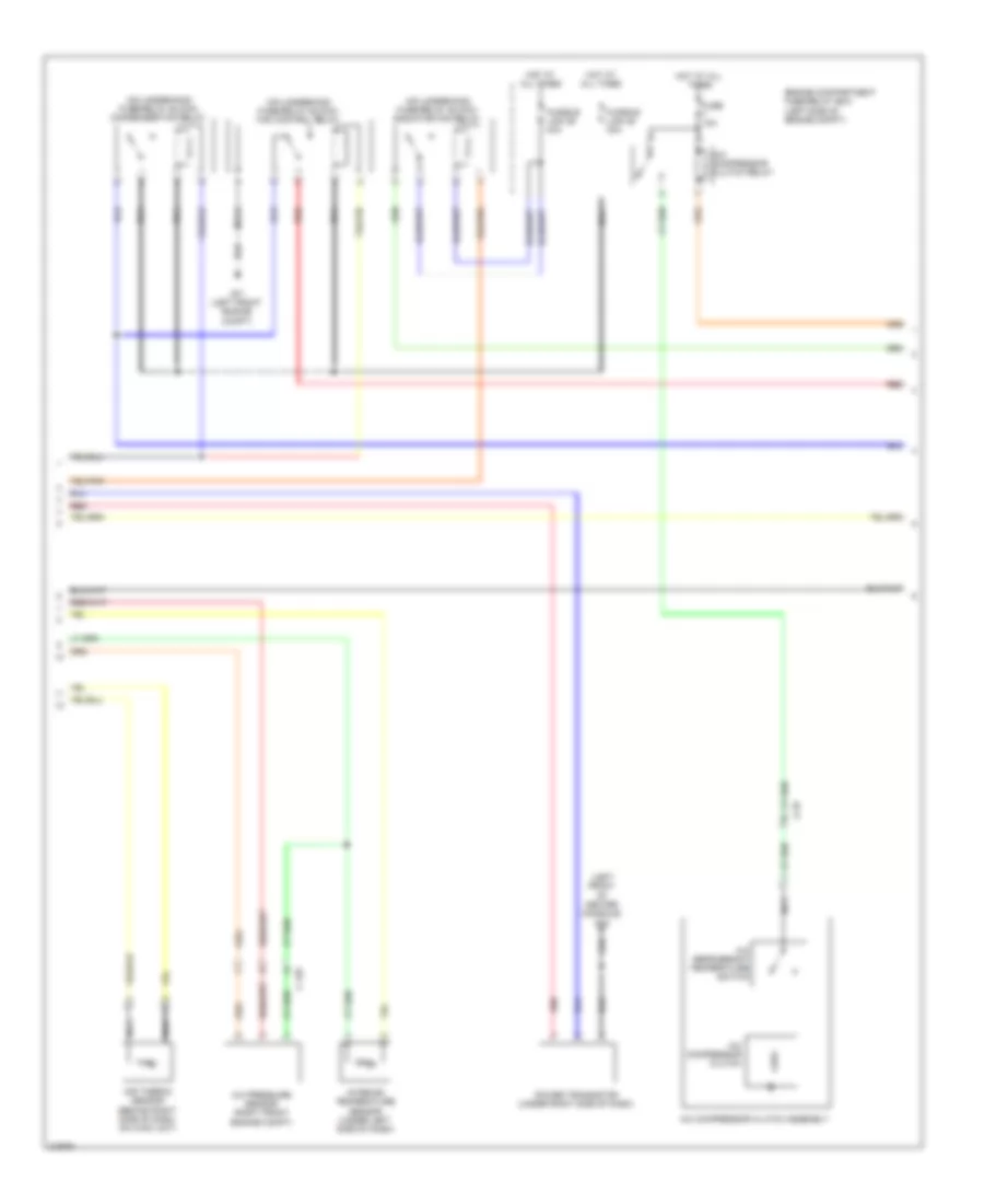
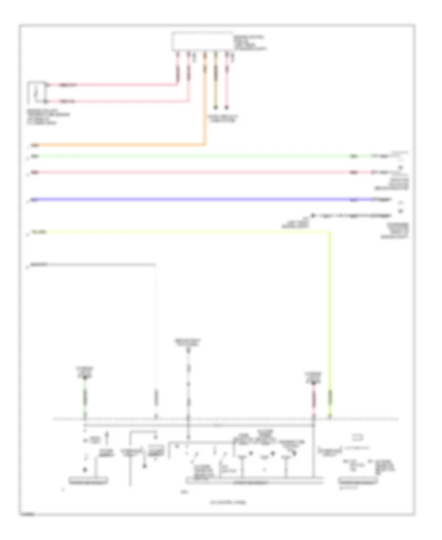
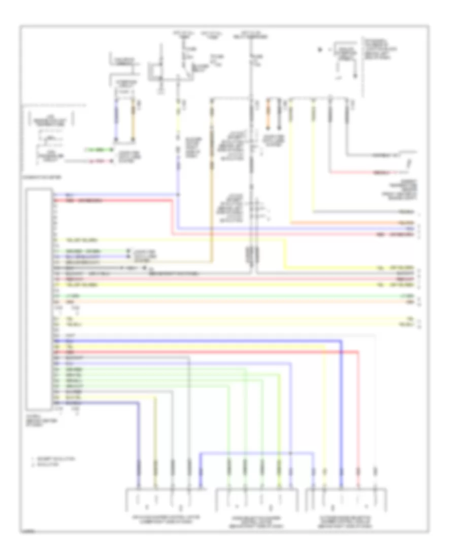
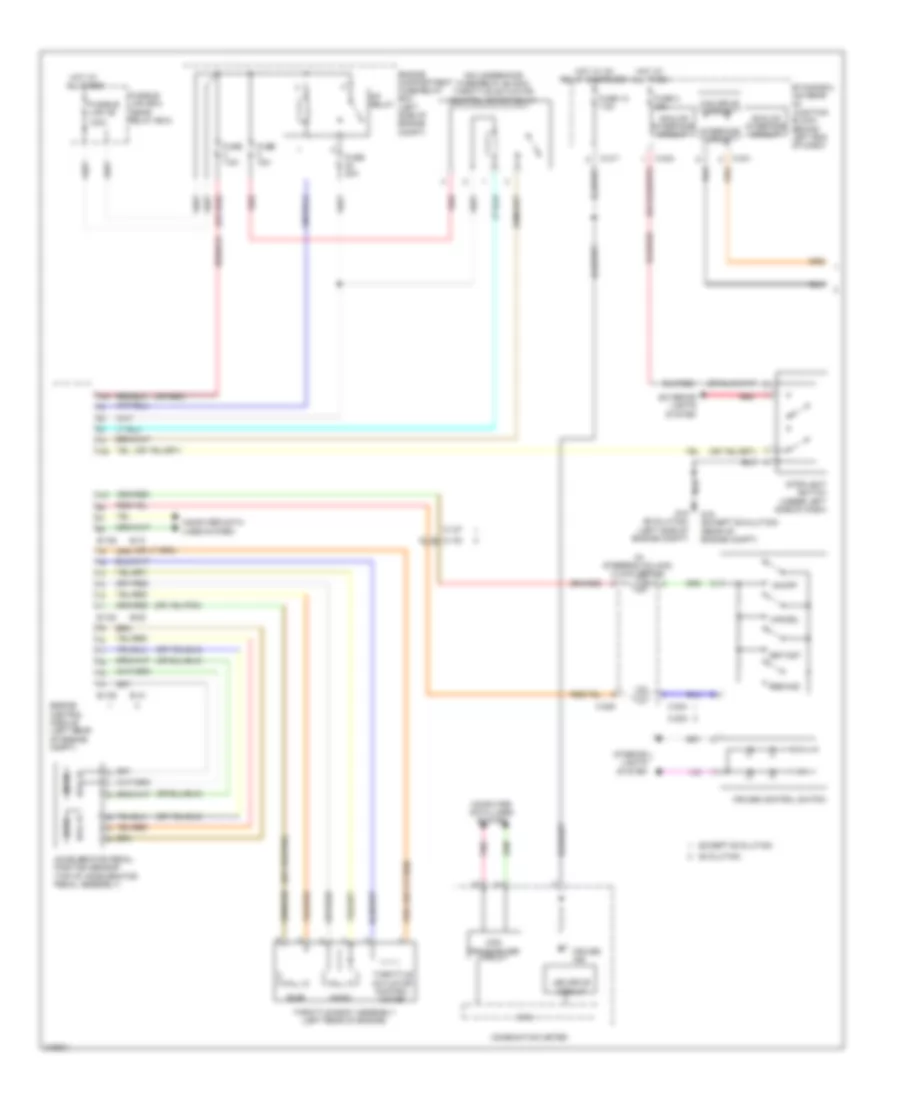
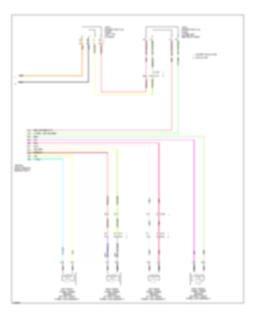
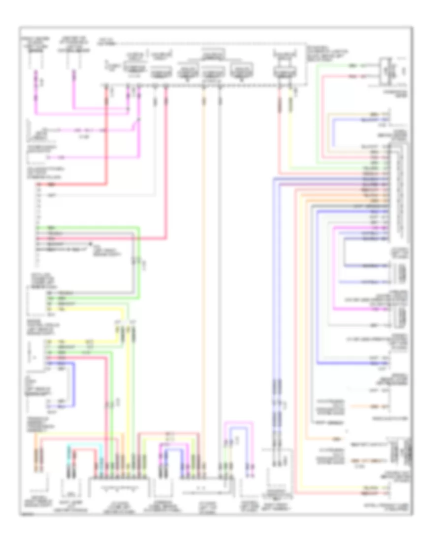
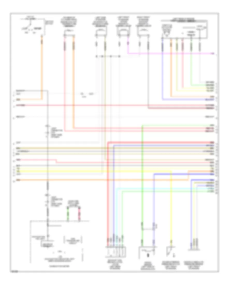
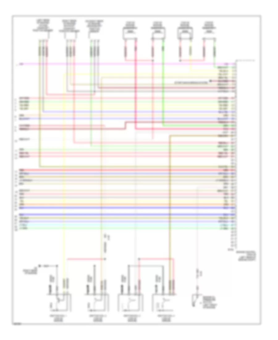
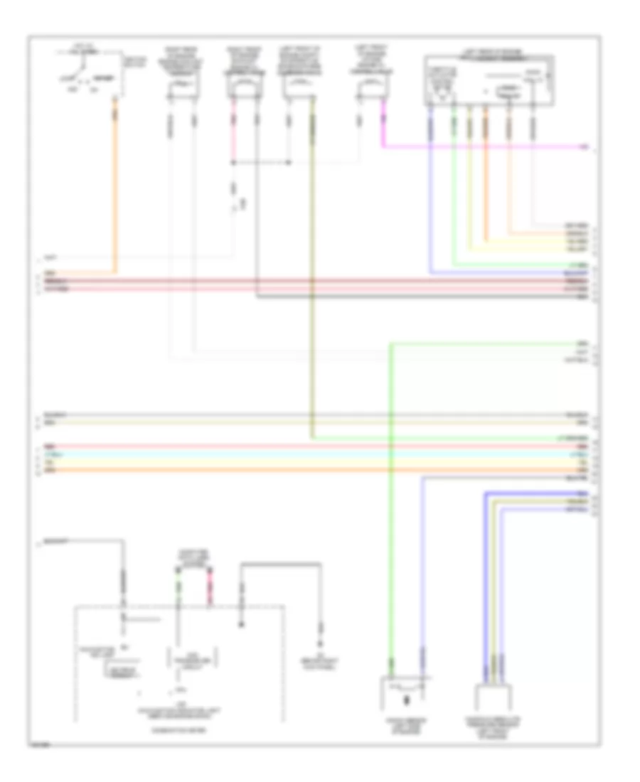
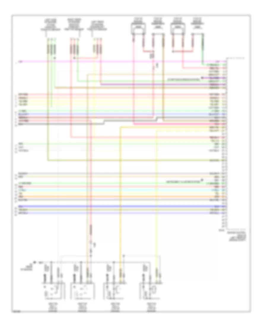
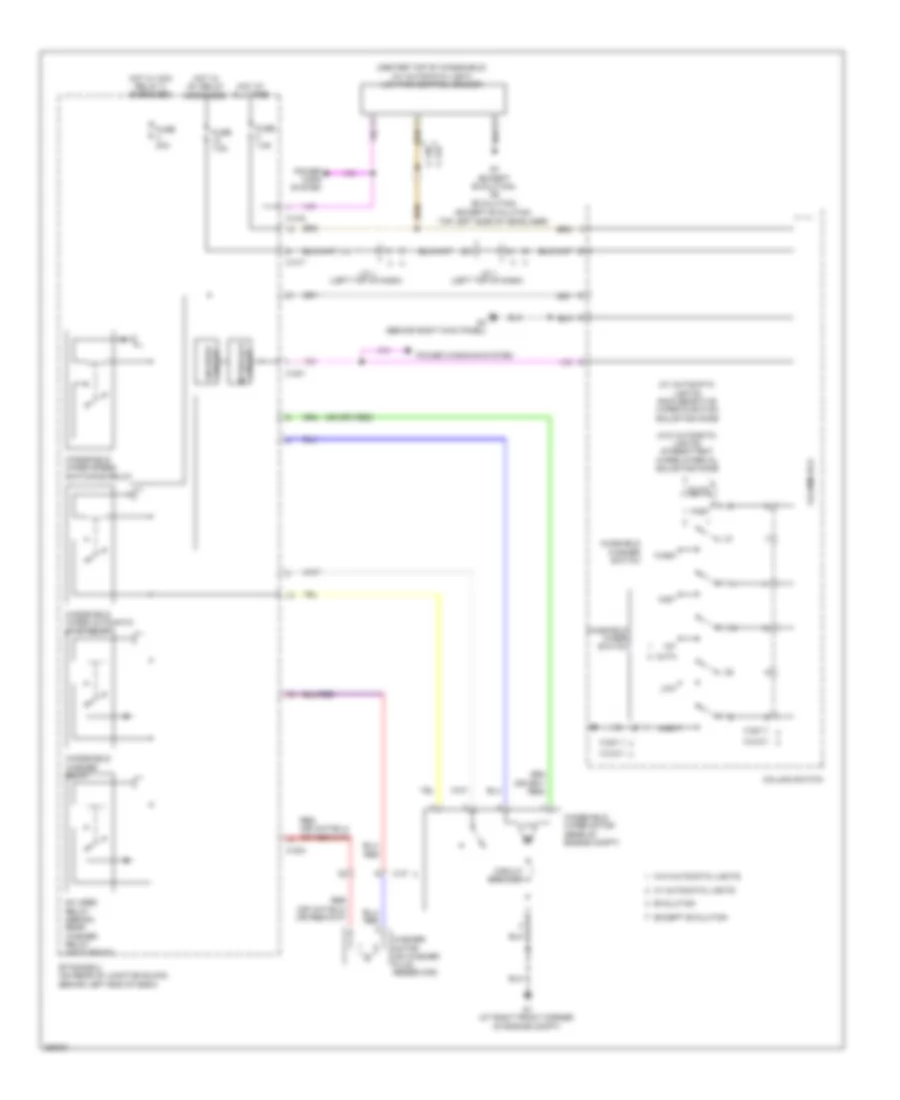
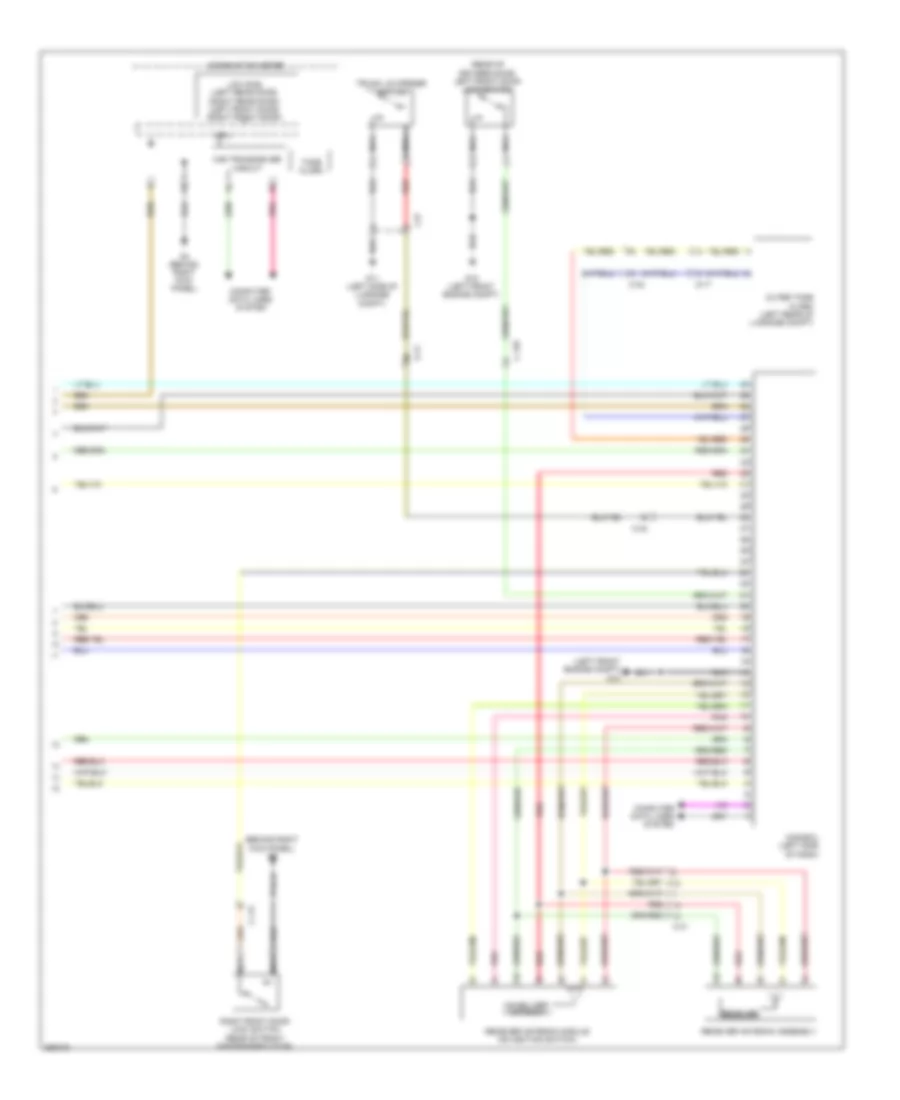
Автомтическая коробка Передач (АКПП) Полная привод (4WD) Блокировка Дифференциала
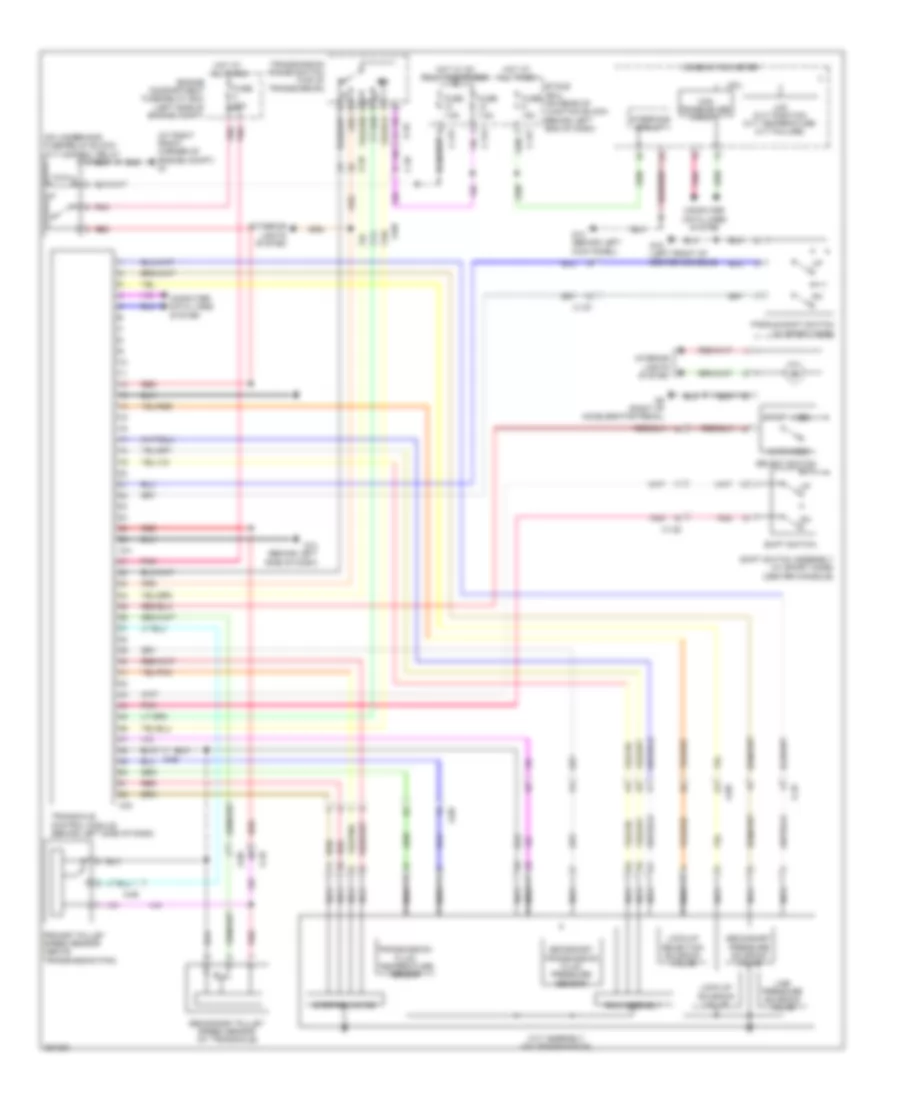
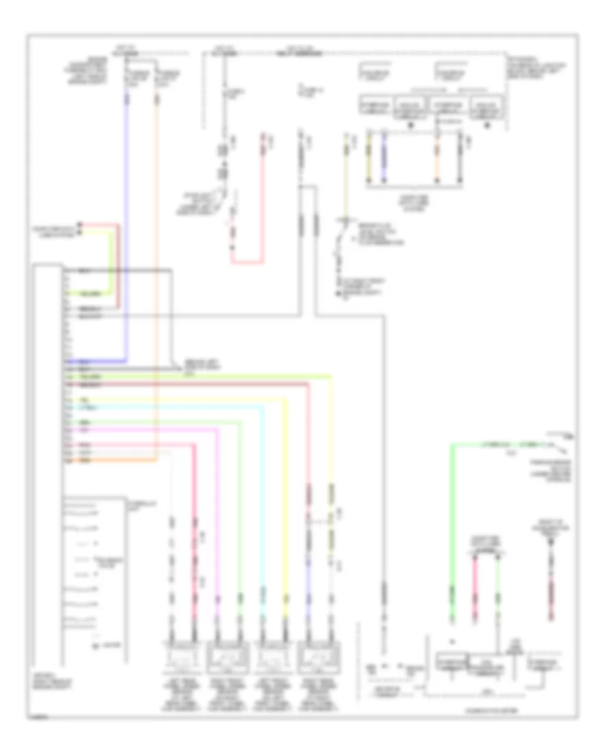
Электросхема коробки передач АКПП, эволюция для Mitsubishi Lancer DE 2011


Электросхема коробки передач АКПП, эволюция для Mitsubishi Lancer DE 2011 - Список элементов:
- A-13
- Acc relay 2 energized
- C-130
- C-27
- C-315
- C-317
- C-35
- Can transceiver circuit
- Combination meter
- Computer data lines system
- Cpu
- Engine compartment fuse/relay box (left side of engine compt)
- Etacs-ecu (on rear of junction block, behind left end of dash)
- Fuse 10a
- Fuse 15a
- Fuse 20a
- Fuse 7.5a
- G17 (left front engine compt)
- G18 (left front engine compt)
- G19 (left side engine compt)
- G3 (left rear of engine)
- Hot at all times
- Hot w/
- Ig1 relay energized
- Ill
- Interface circuit
- Interior
- Lcd (shift position normal sport s-sport)
- Lights system
- Low side switch
- Manual
- Mode (+)
- Mode (-)
- Nca
- Paddle shift switch
- Pnk
- Red
- Shift lever (center console)
- Shift lever position indicator panel
- Shift lever position sensor (p,r,n,d,m,+,-)
- Transaxle assembly (transmission assembly)
- Twin clutch sport shift transaxle control module switch
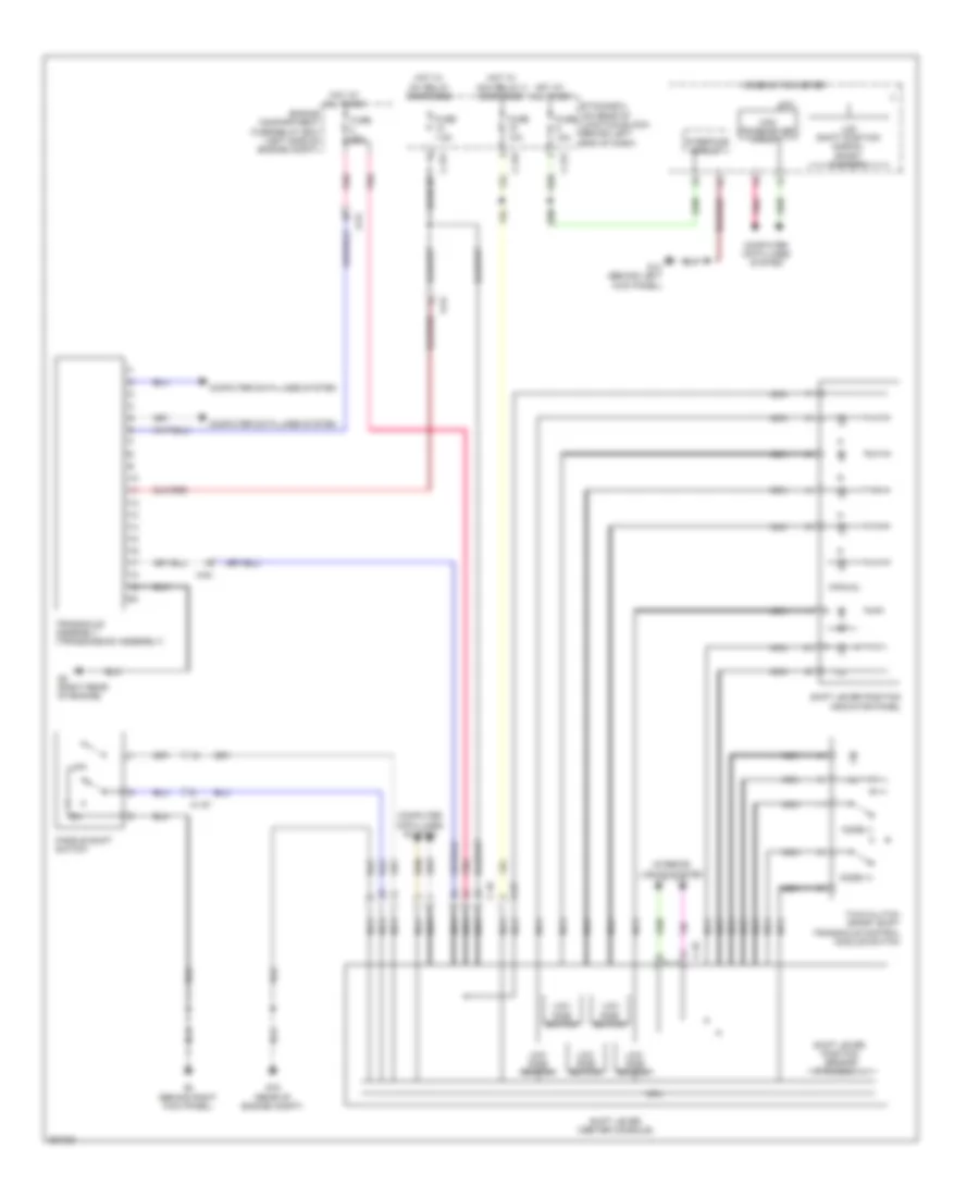
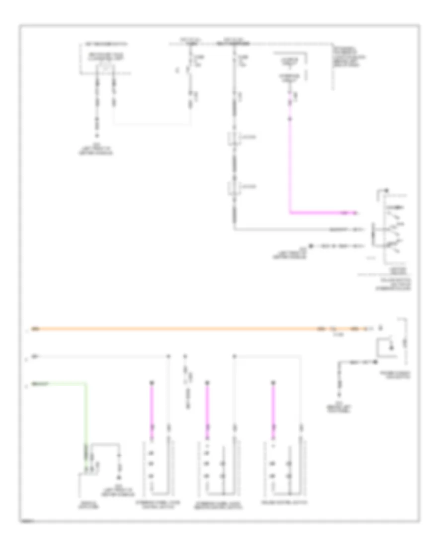
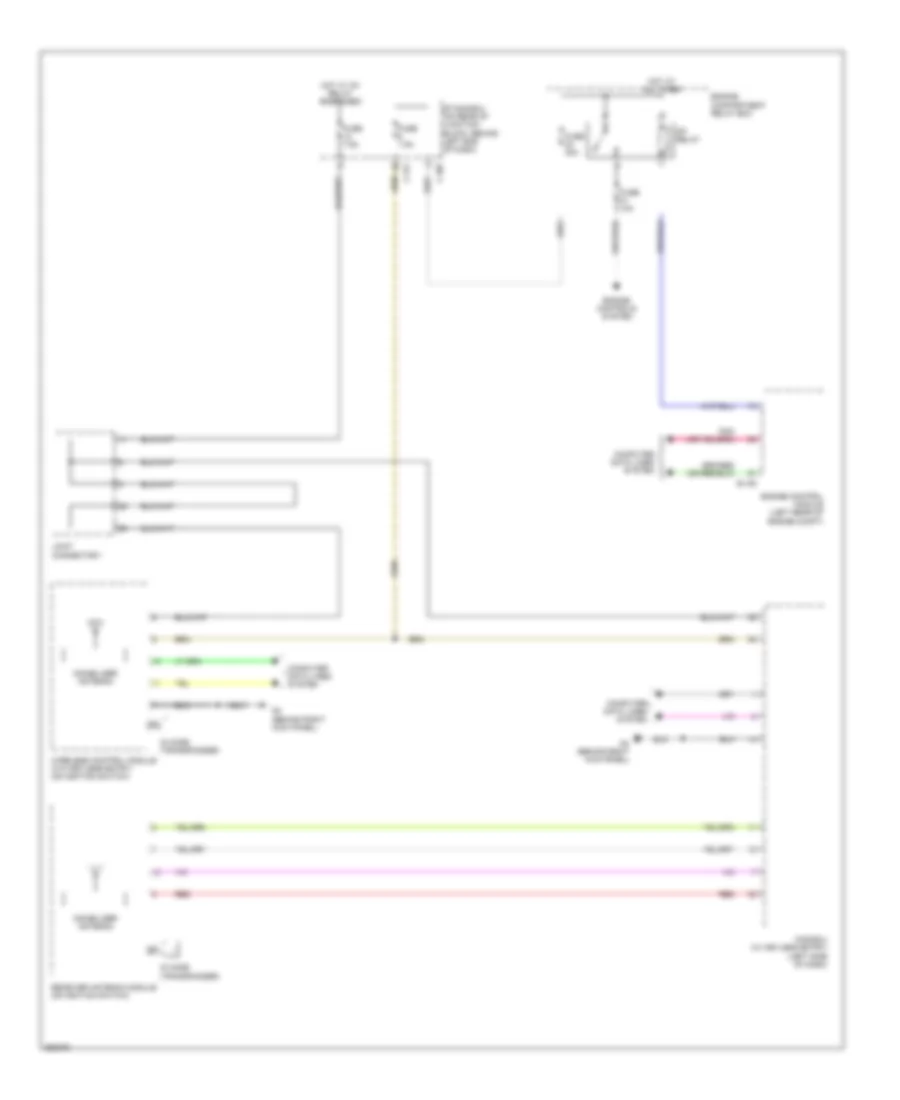
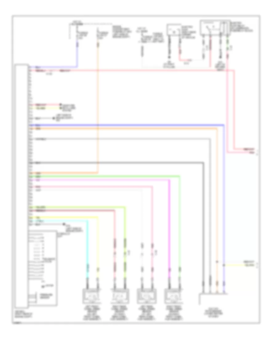
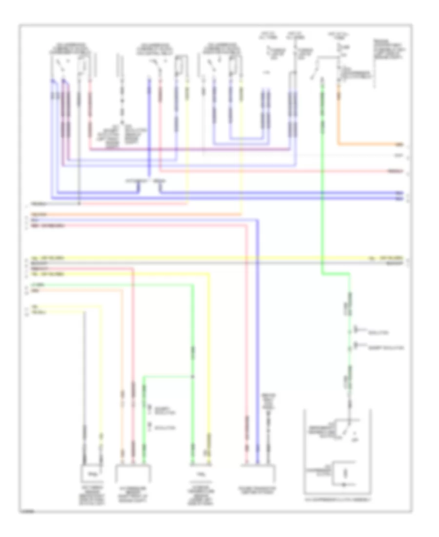
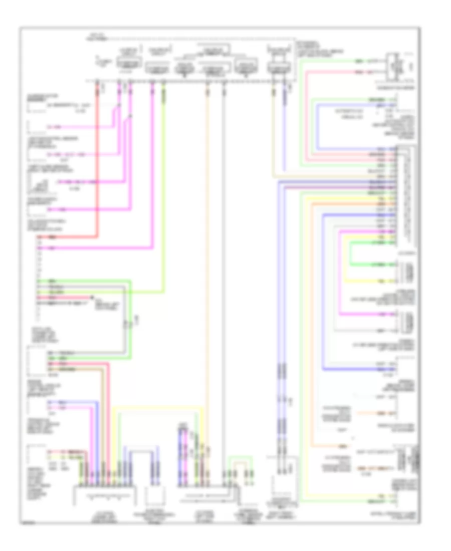
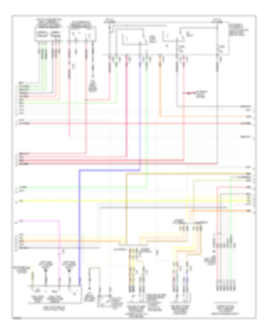
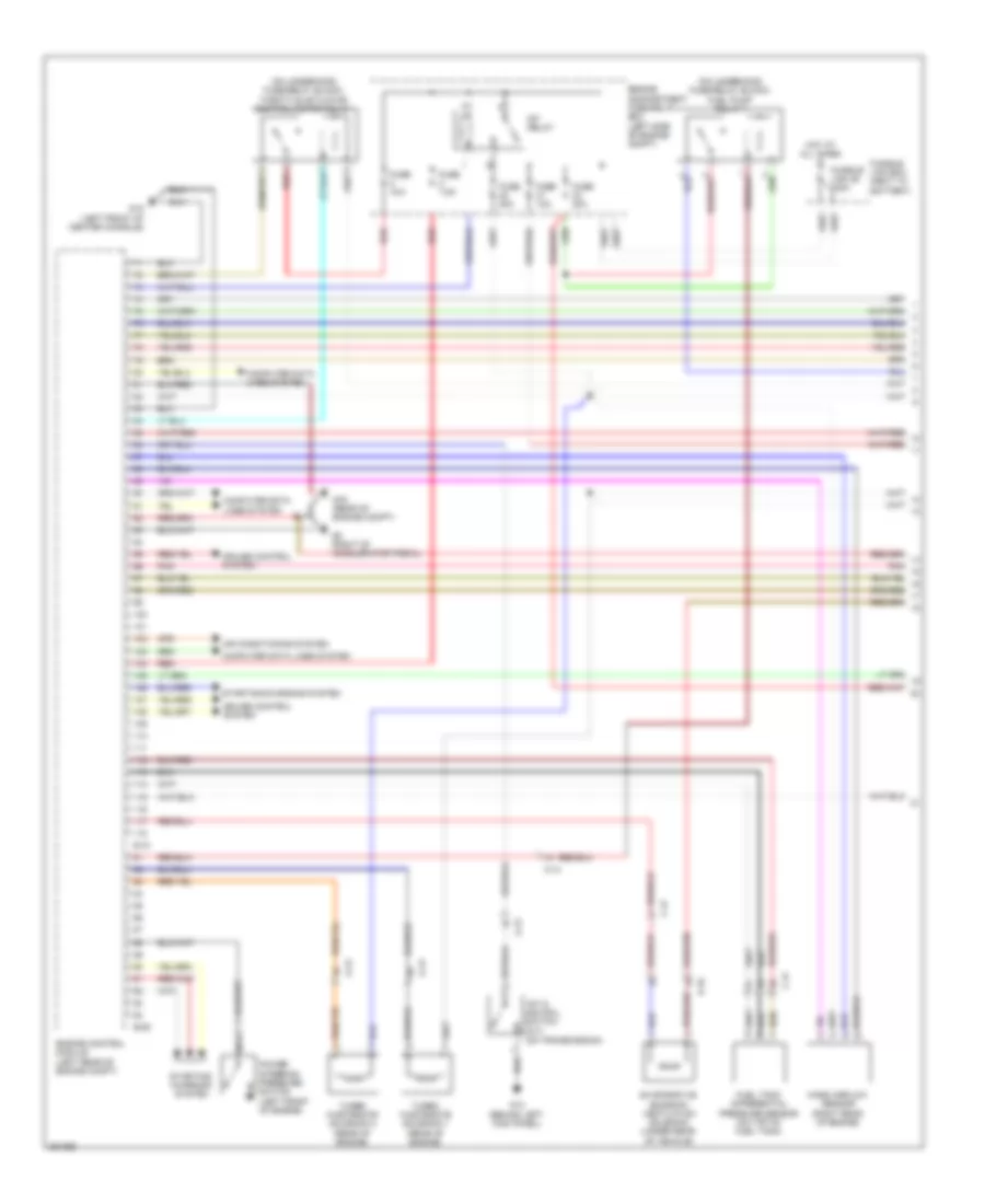
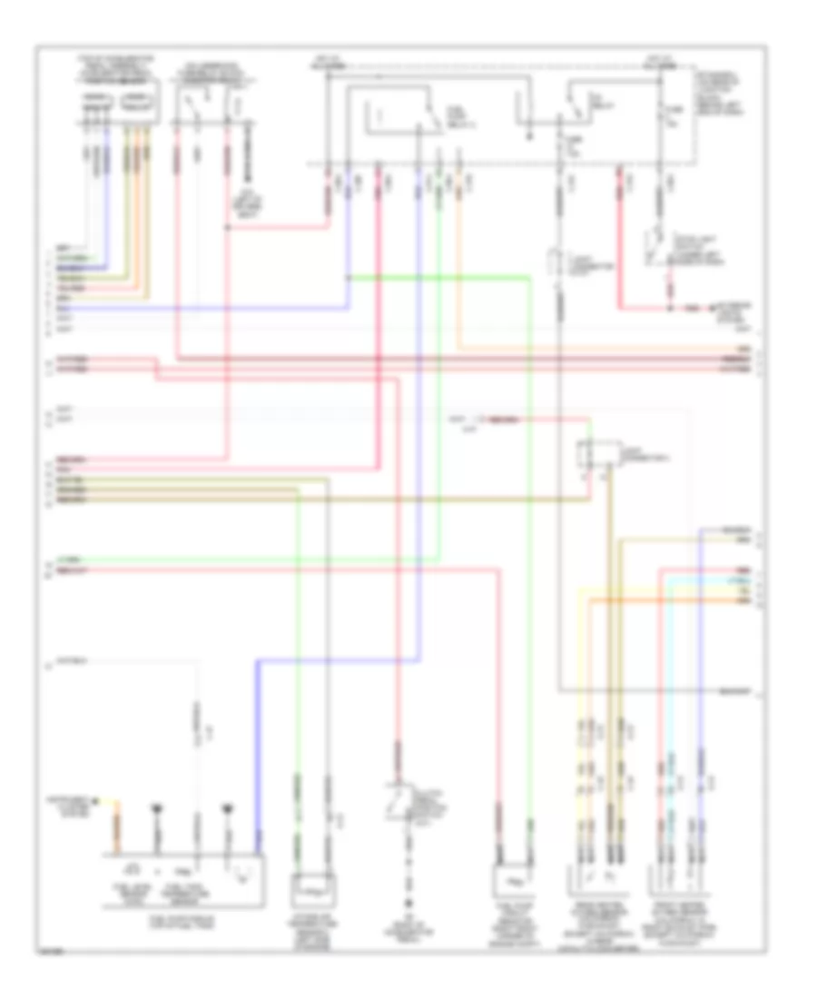
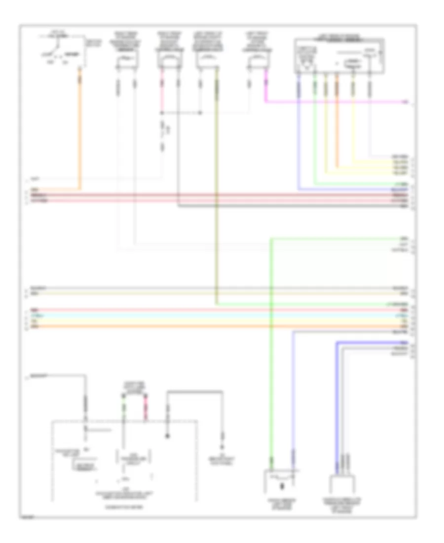
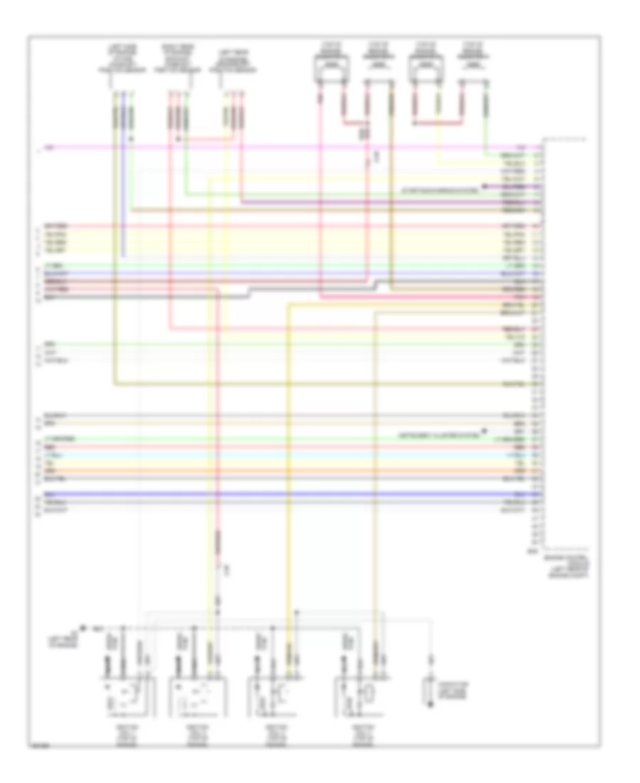
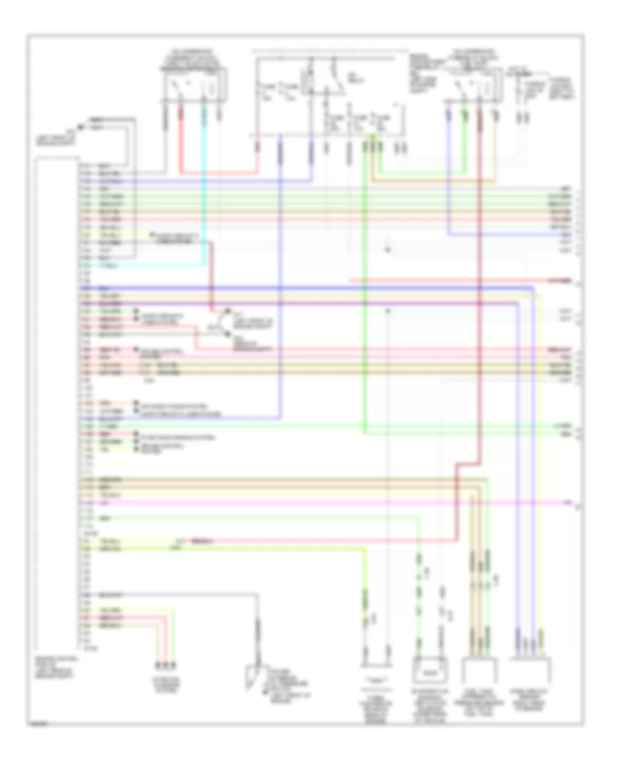
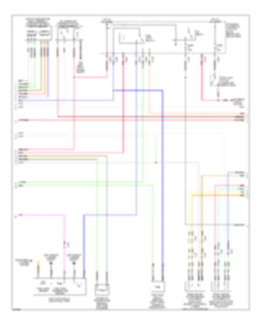
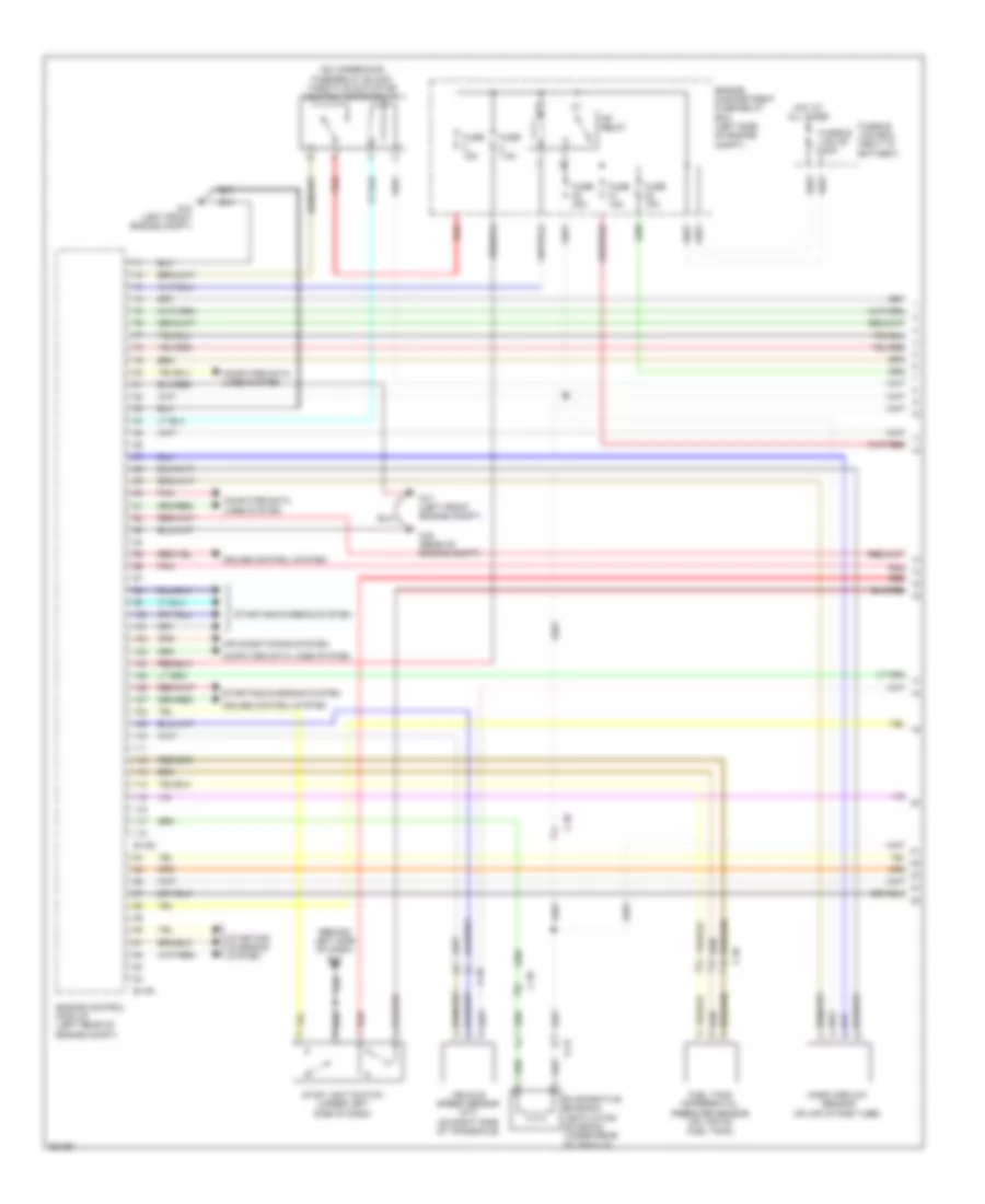
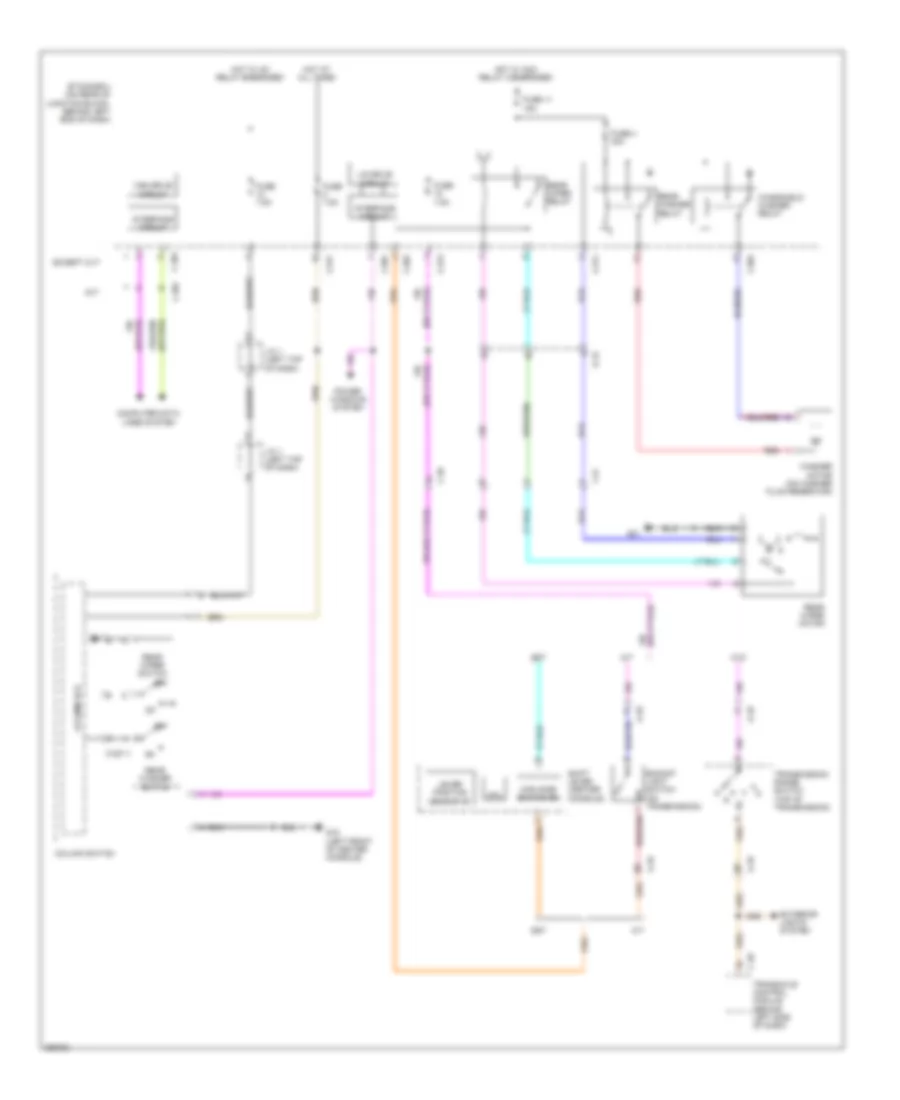
Электросхема коробки передач АКПП, кроме эволюции, CVT для Mitsubishi Lancer DE 2011
Электросхема коробки передач АКПП, кроме эволюции, CVT для Mitsubishi Lancer DE 2011 - Список элементов:
- (at right front corner of engine compt) g1
- (center console)
- (on underhood fuse/relay block) cvt control relay
- A-09
- A-10
- Auto mode
- C-127
- C-128
- C-313
- C-317
- C-39
- C40
- C41
- Can transceiver circuit
- Combination meter
- Computer data lines system
- Cpu
- Cvt assembly (on transmission)
- Engine compartment fuse/relay box (left side of engine compt)
- Etacs -ecu (on rear of junction block, behind left end of dash)
- Exterior lights system
- Fuse 15a
- Fuse 20a
- Fuse 7.5a
- G13 (behind left side of dash)
- G14 (behind left kick panel)
- G15 (left front of center console)
- G5 (right of accelerator pedal)
- Hot at all times
- Hot w/ ig1 relay energized
- Ill
- Interface circuit
- Interior lights system
- Lcd (cvt position cvt temperature cvt failure)
- Line pressure solenoid valve
- Lock-up selection solenoid valve
- Lock-up solenoid valve
- Nca
- Paddle shift switch (w/ sport mode)
- Pnk
- Primary pulley speed sensor (above transmission pan)
- Red
- Rom-assembly
- Secondary pressure solenoid valve
- Secondary pulley speed sensor (at transaxle)
- Secondary transmission fluid pressure sensor
- Select switch
- Shift switch
- Shift switch assembly (w/ sport mode)
- Sport mode
- Stepper motor
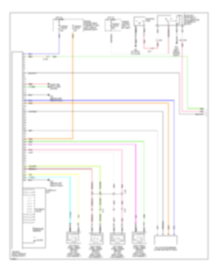
- Transaxle control module (behind left side of dash)
- Transmission fluid temperature sensor
- Transmission range switch (top of transmission)
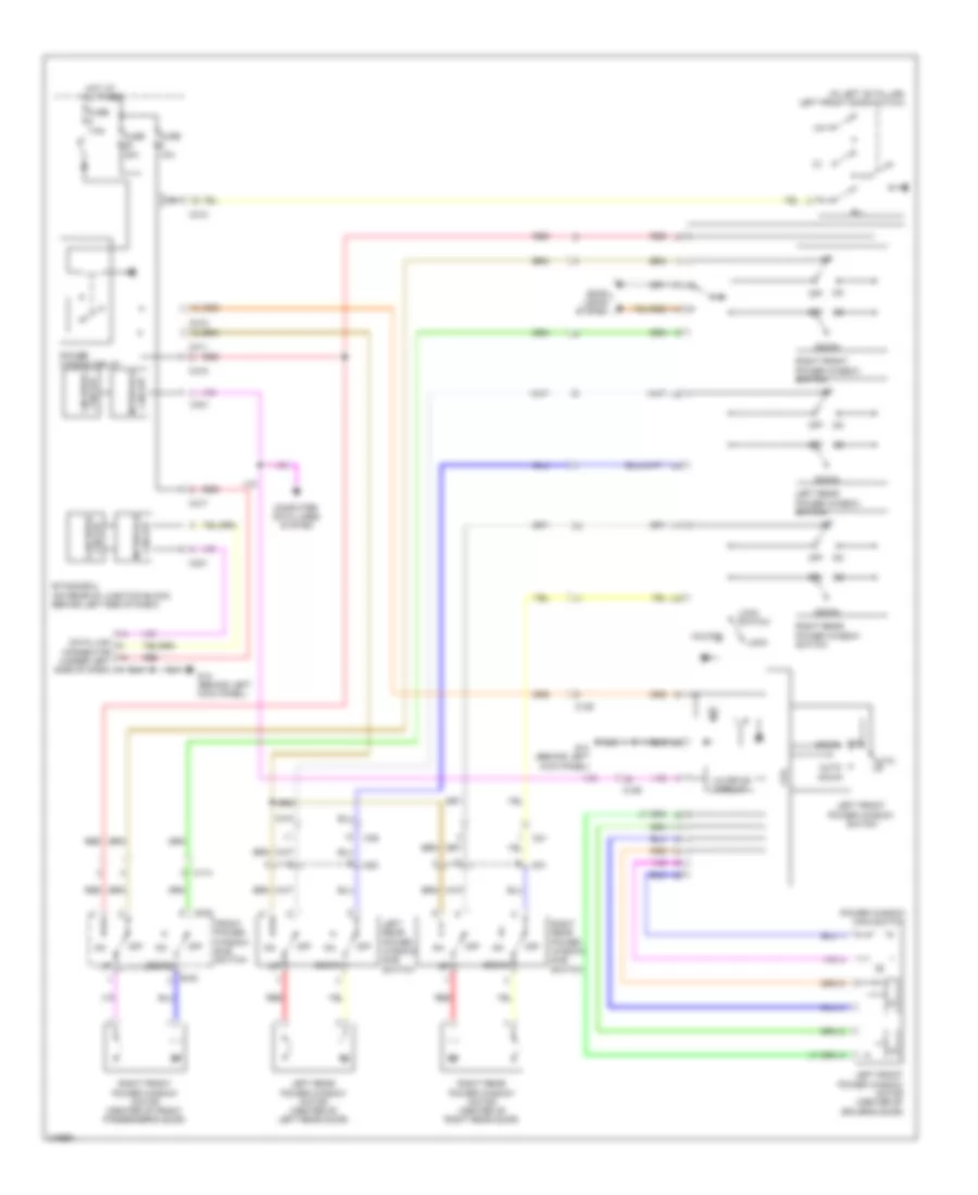
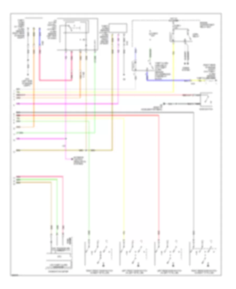
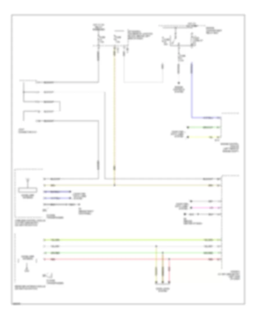
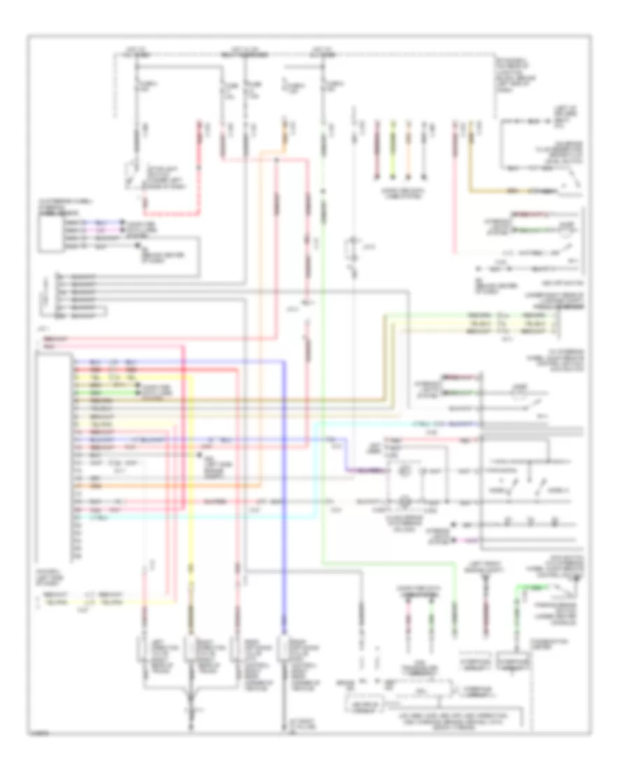
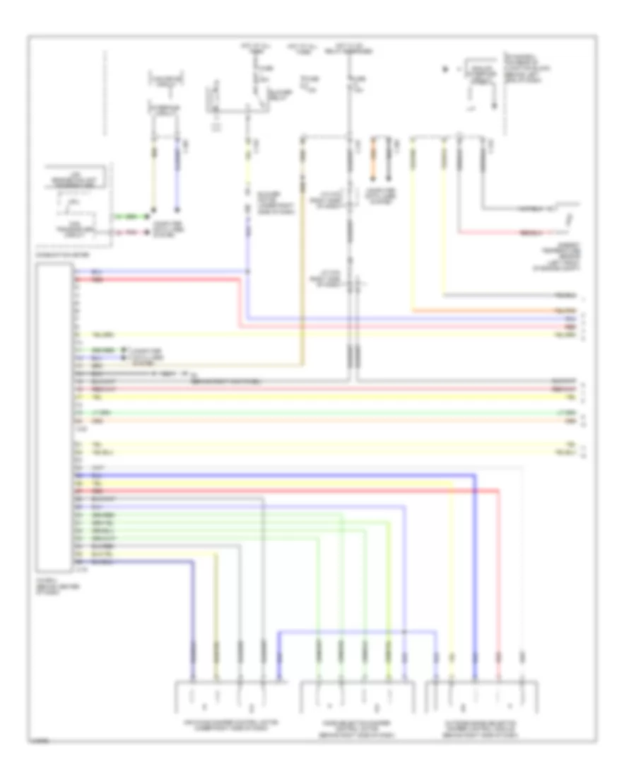
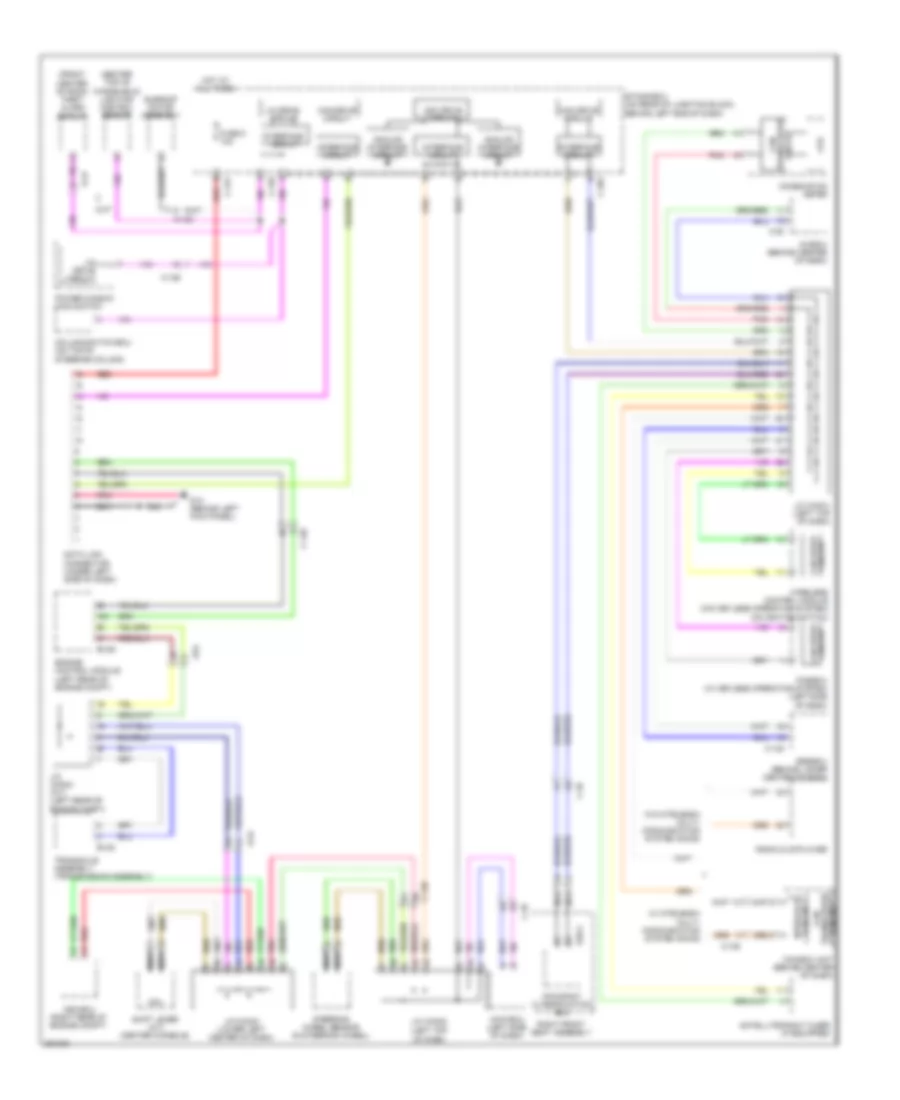
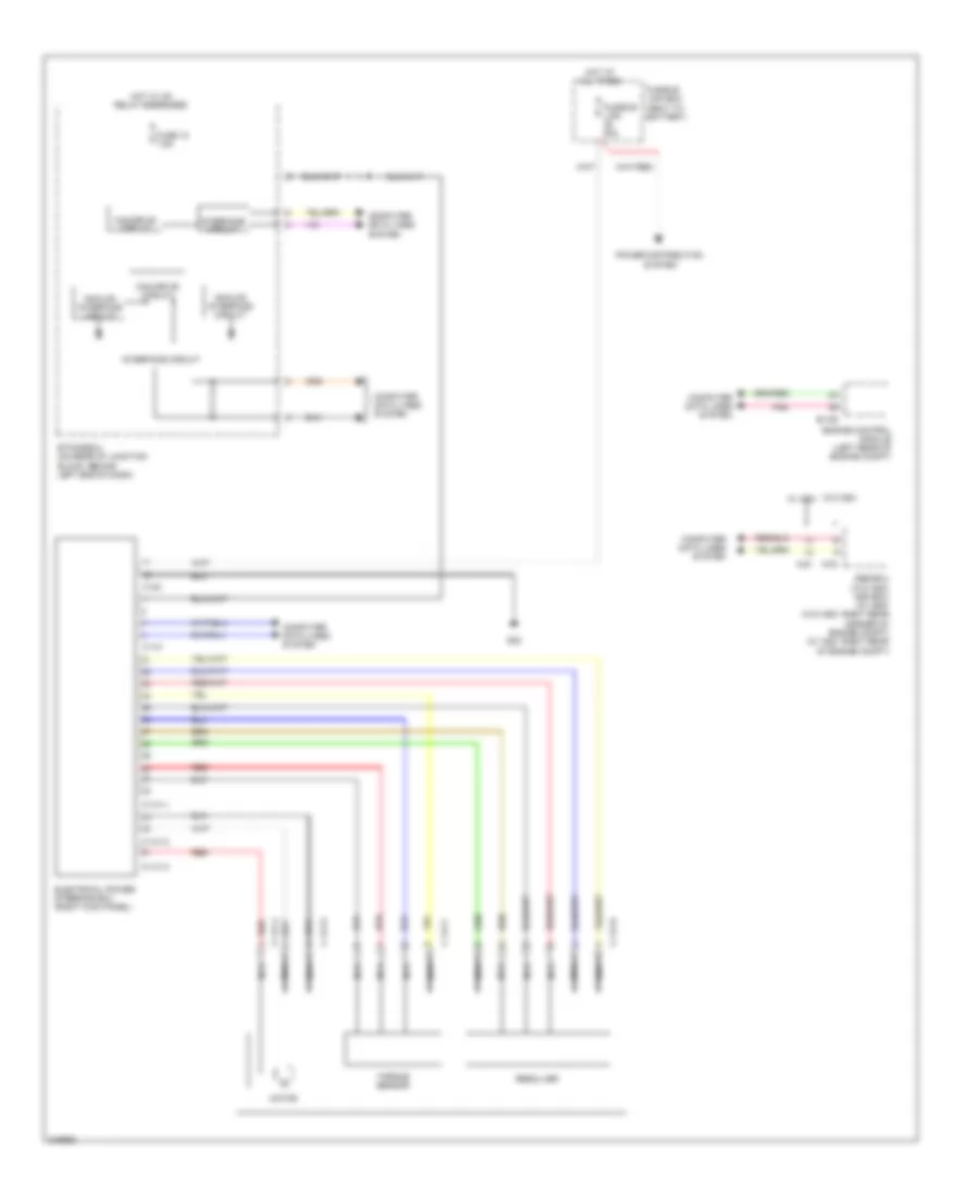
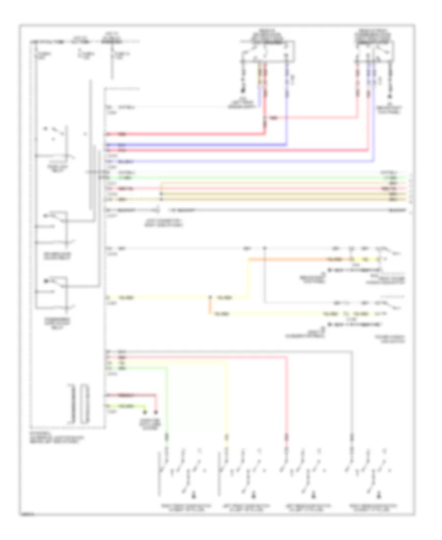
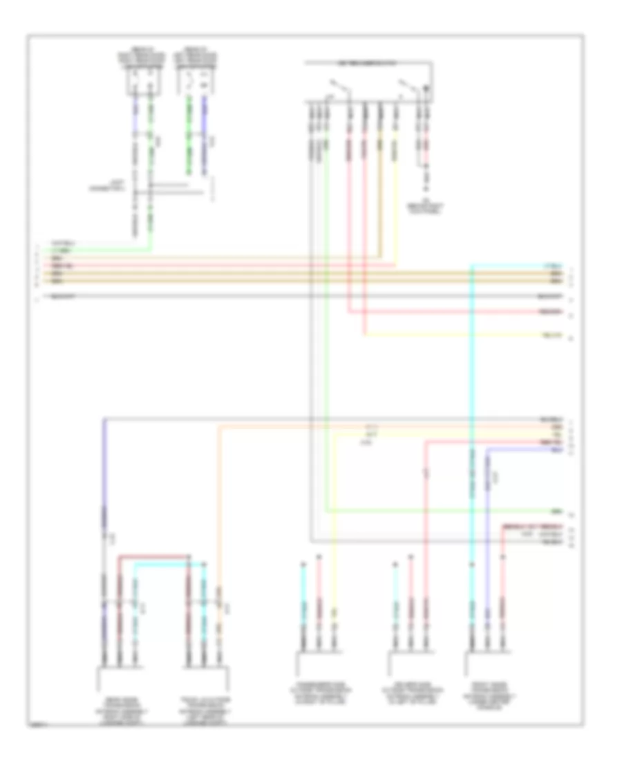
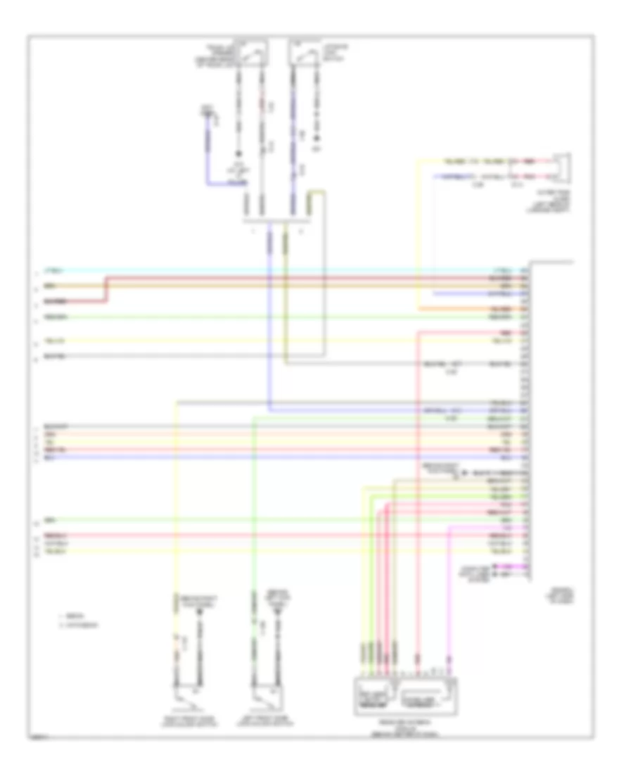
Электросхема коробки передач АКПП, кроме эволюции, TC-SST для Mitsubishi Lancer DE 2011
Электросхема коробки передач АКПП, кроме эволюции, TC-SST для Mitsubishi Lancer DE 2011 - Список элементов:
- A-54
- Acc relay 2 energized
- C-127
- C-27
- C-315
- C-317
- C-49
- Can transceiver circuit
- Combination meter
- Computer data lines system
- Cpu
- Engine compartment fuse/relay box (left side of engine compt)
- Etacs-ecu (on rear of junction block, behind left end of dash)
- Fuse 10a
- Fuse 15a
- Fuse 20a
- Fuse 7.5a
- G14 (behind left kick panel)
- G16 (rear of engine compt)
- G2 (right rear of engine)
- G4 (behind right kick panel)
- Hot at all times
- Hot w/
- Ig1 relay energized
- Ill
- Interface circuit
- Interior
- Lcd (shift position normal sport s-sport)
- Lights system
- Low side switch
- Manual
- Mode (+)
- Mode (-)
- Nca
- Paddle shift switch
- Pnk
- Shift lever (center console)
- Shift lever position indicator panel
- Shift lever position sensor (p,r,n,d,m,+,-)
- Transaxle assembly (transmission assembly)
- Twin clutch sport shift transaxle control module switch
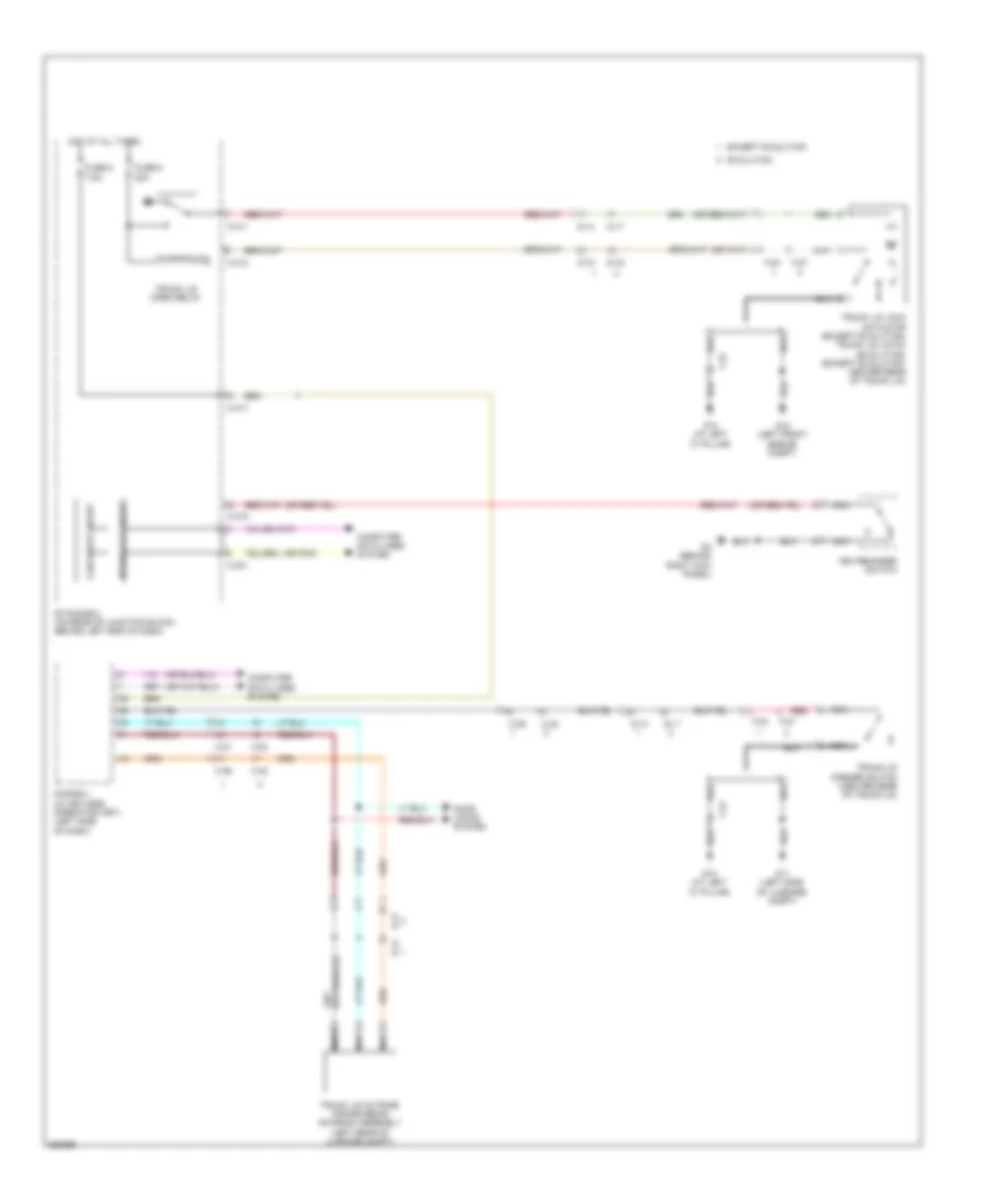
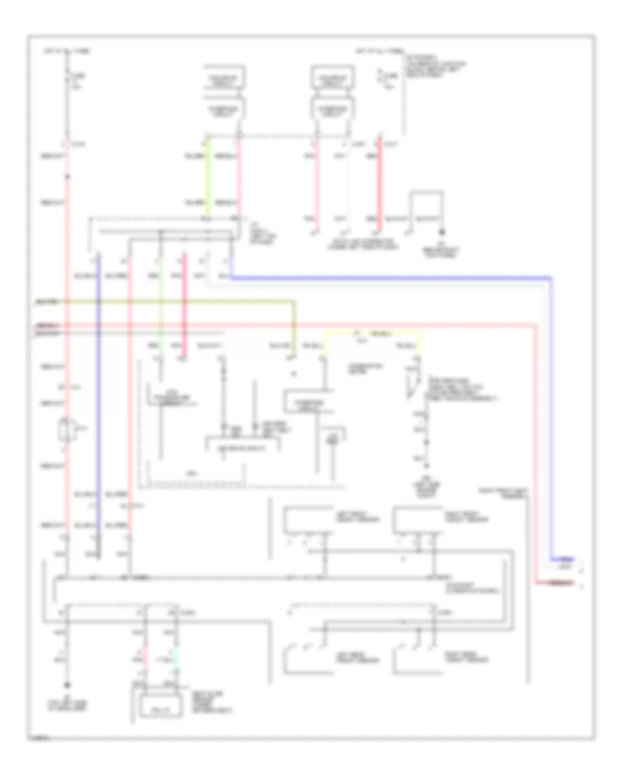
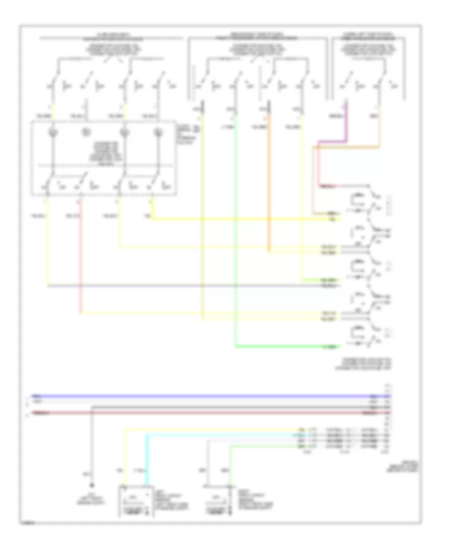
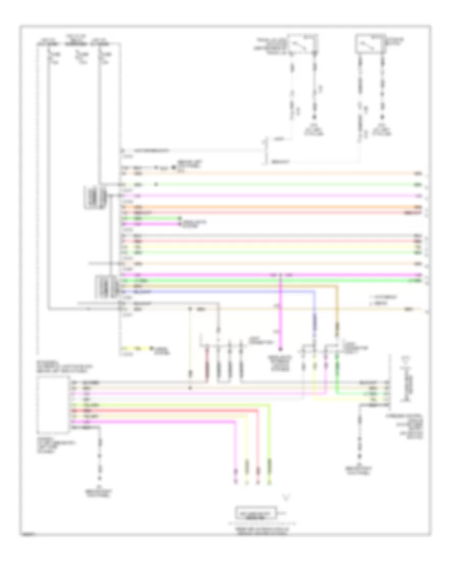
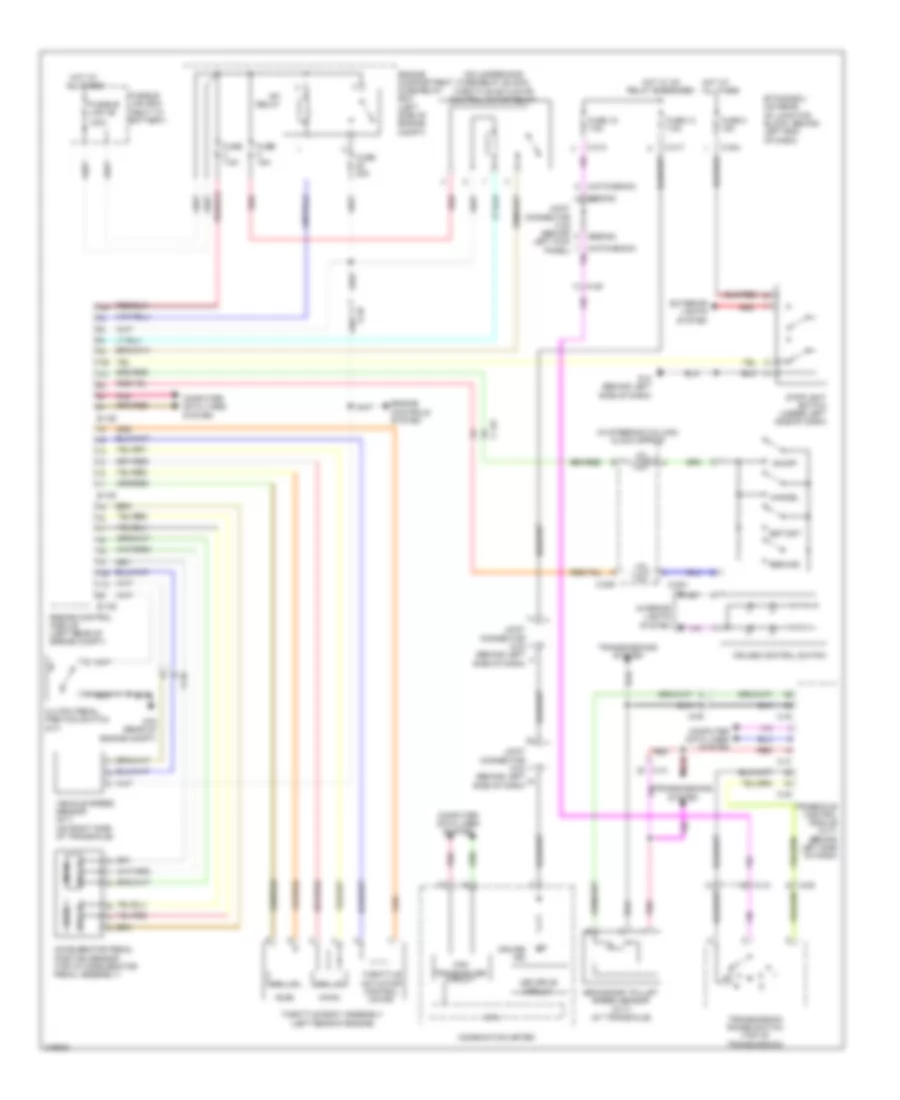
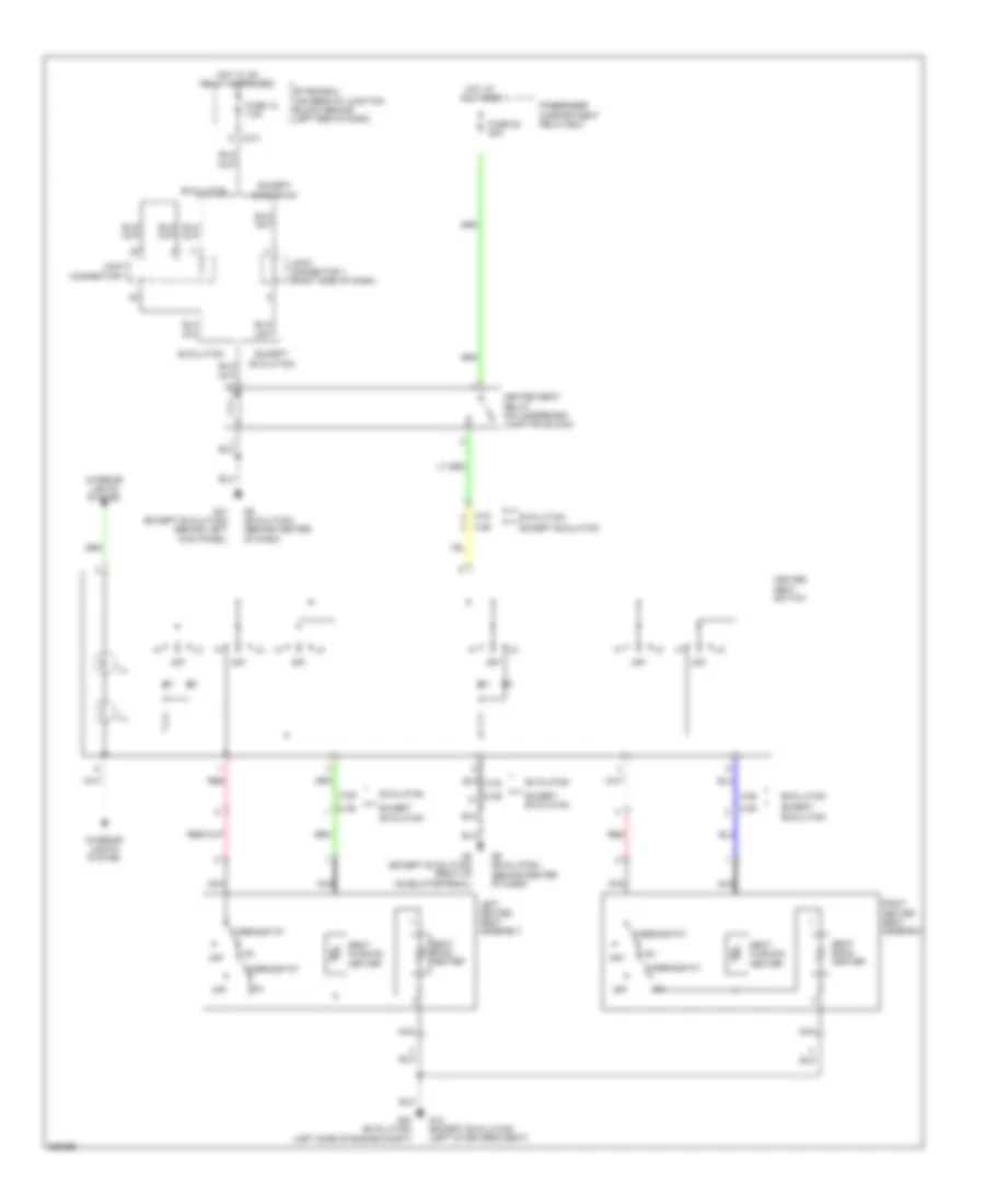
БАГАЖНИК ЗАДНЯЯ ДВЕРЬ ЛЮЧОК ТОПЛИВНОГО БАКА
Электросхема открывания багажника для Mitsubishi Lancer DE 2011
Электросхема открывания багажника для Mitsubishi Lancer DE 2011 - Список элементов:
- (or pnk)
- C-21
- C-23
- C-301
- C-311
- C-313
- C-315
- C-317
- C-36
- C-42
- Can drive circuit
- Computer data lines system
- D-14
- D-15
- D-16
- D-17
- Door locks system
- Etacs-ecu (on rear of junction block, behind left end of dash)
- Evolution
- Except evolution
- F-23
- F-27
- Fuse 6 20a
- Fuse 8 7.5a
- G10 (at left "c" pillar)
- G11 (left side of luggage compt)
- G18 (left front engine compt)
- G4 (behind right kick panel)
- Hot at all times
- Interface circuit
- Key reminder switch
- Kos-ecu (w/ keyless operation key) (left side of dash)
- Nca
- Red
- Trunk lid lock actuator (except evolution) trunk lid latch (evolution) (except evolution: center rear of trunk lid)
- Trunk lid open relay
- Trunk lid opener switch (center rear of trunk lid)
- Trunk lid outside transmission antenna assembly (left rear of luggage compt)
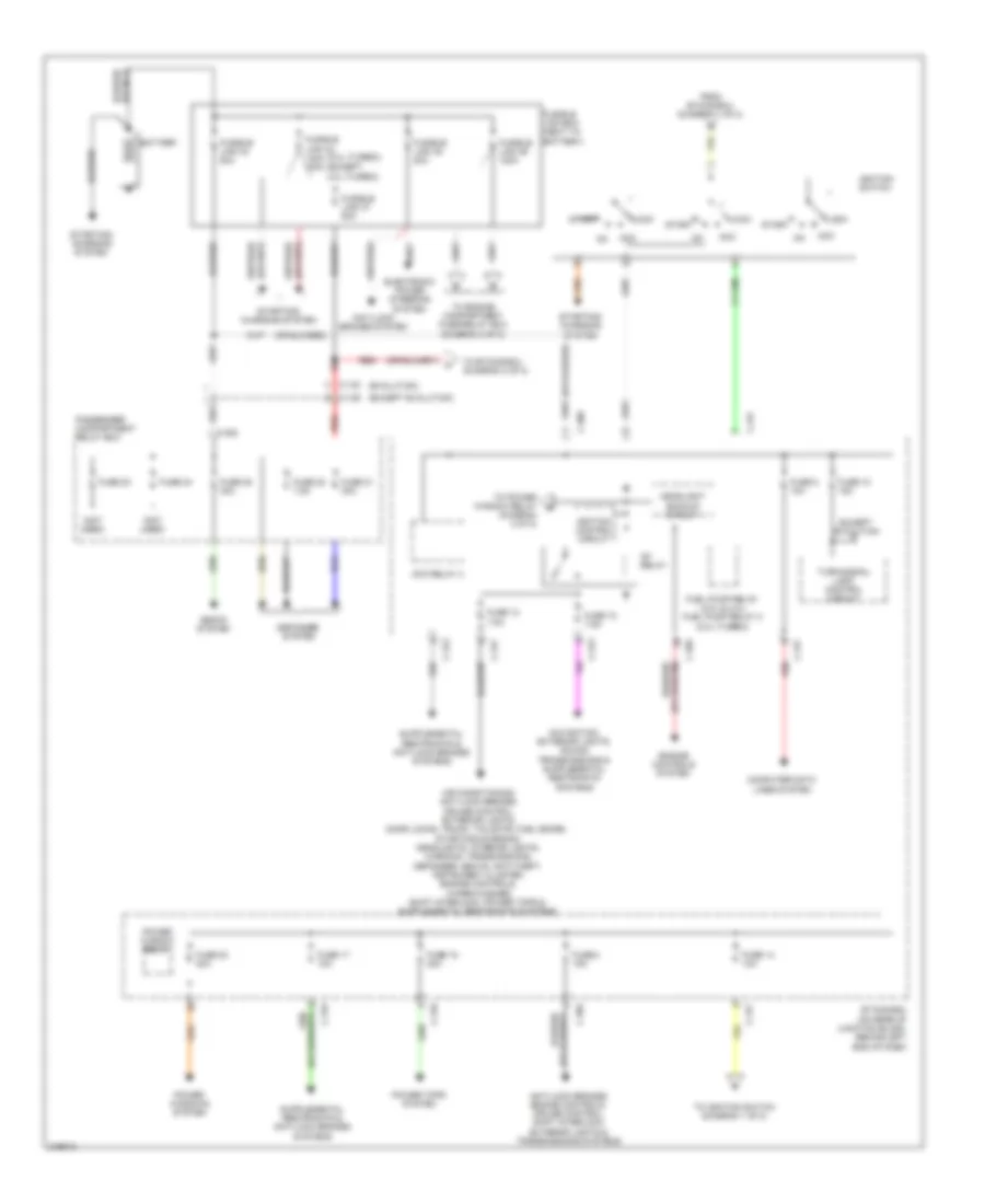
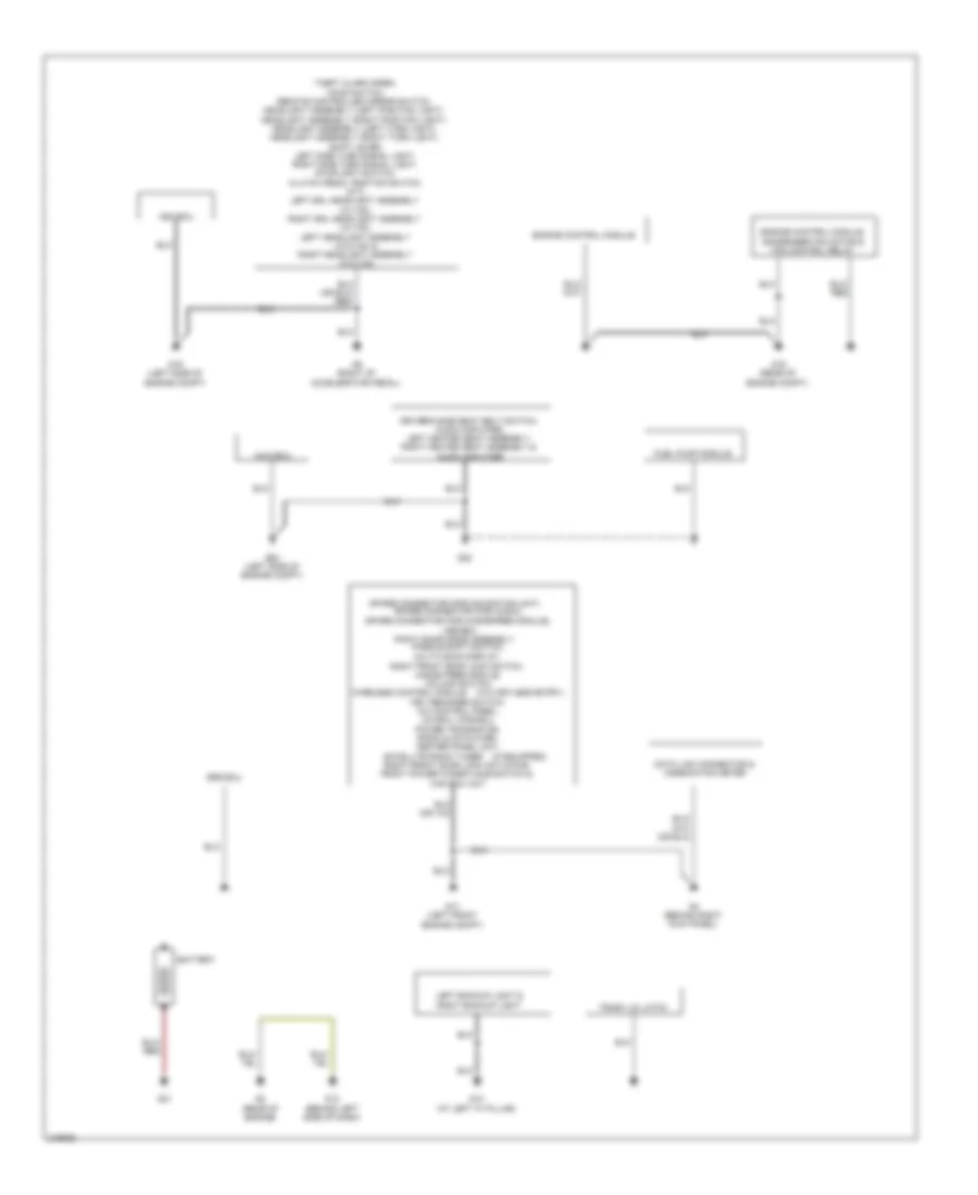
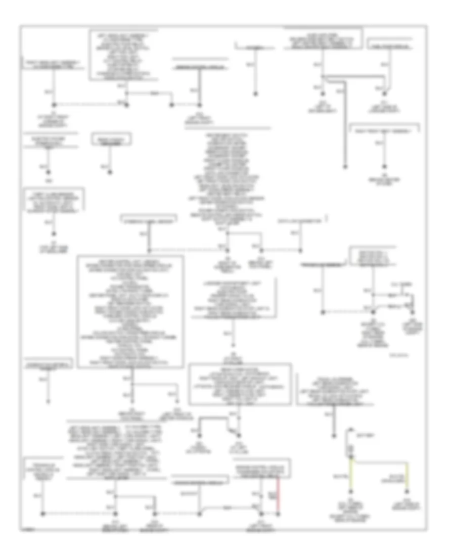
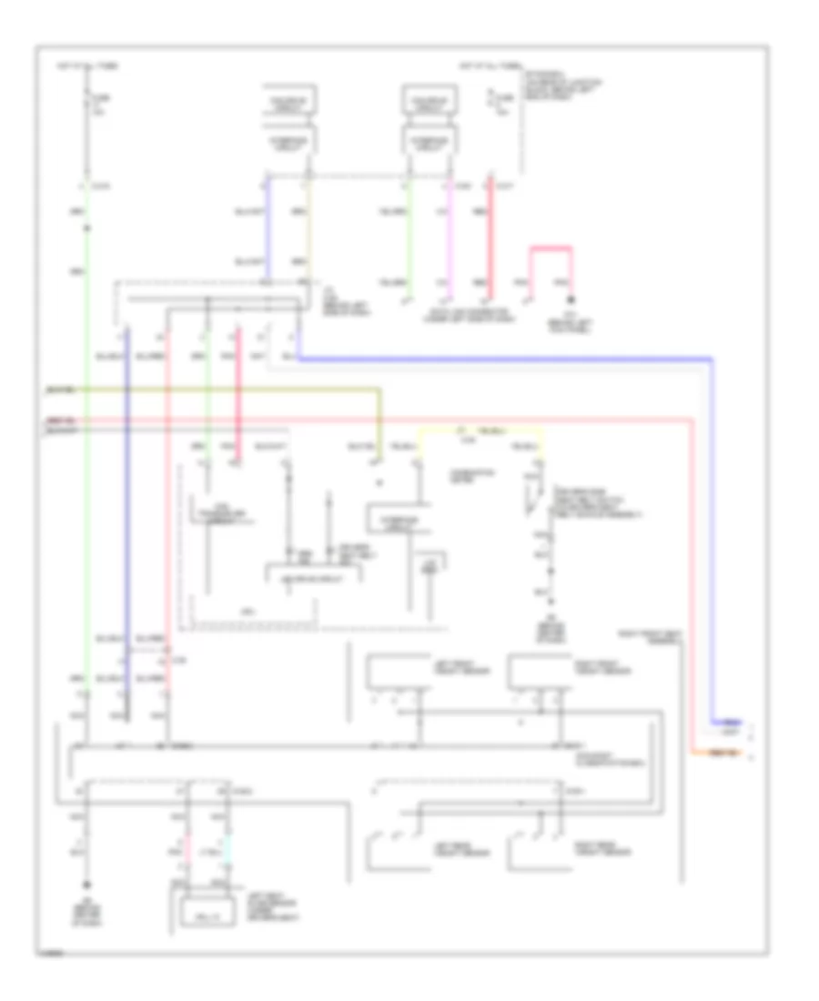
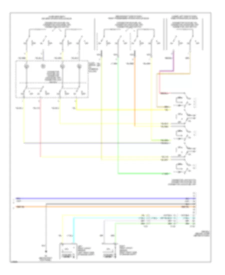
БЛОК ПРЕДОХРАНИТЕЛЕЙ И РЕЛЕ
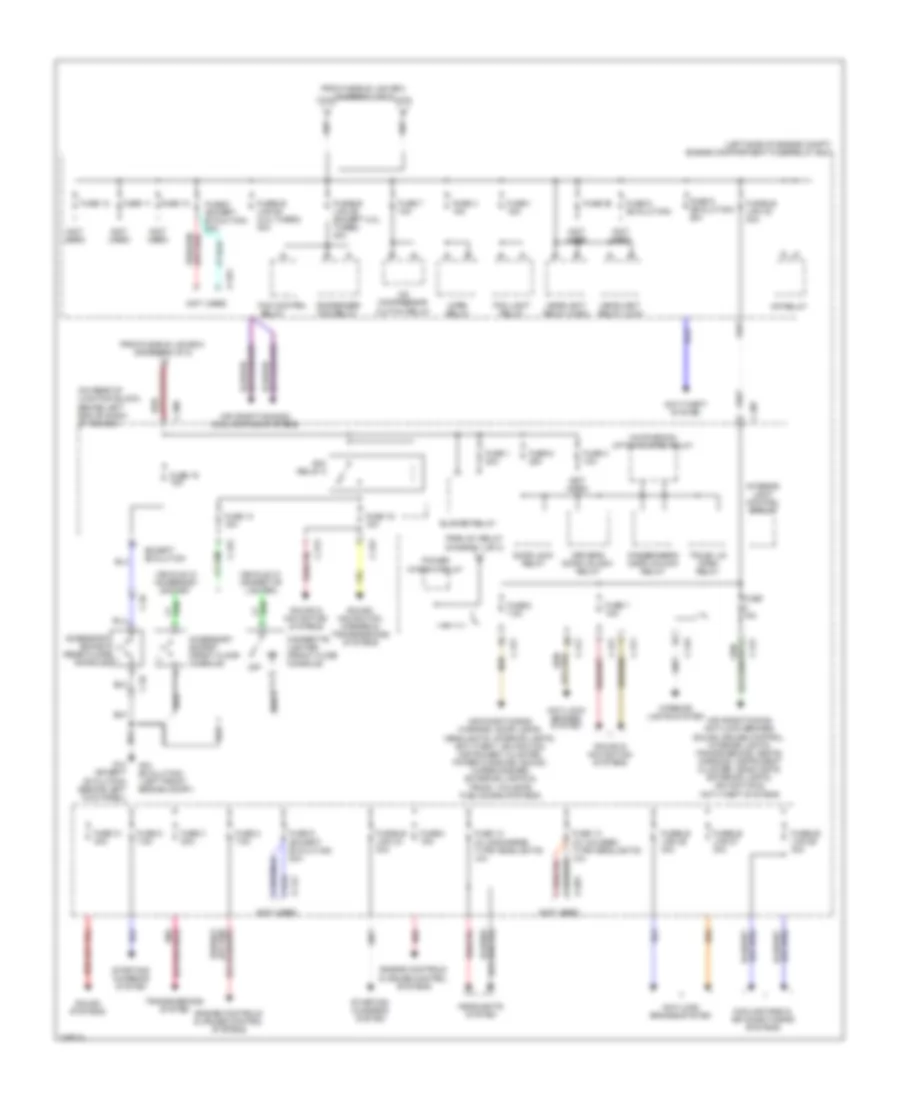
Электросхема блока предохранителей и реле (1 из 2) для Mitsubishi Lancer DE 2011
Электросхема блока предохранителей и реле (1 из 2) для Mitsubishi Lancer DE 2011 - Список элементов:
- (2.0l (turbo))
- (evolution)
- (except 2.0l (turbo))
- (except evolution)
- (not used)
- Acc
- Acc relay 3
- Anti-lock brakes system
- Anti-lock brakes, engine controls, cruise control, shift interlock, exterior lights & transmissions systems
- Battery
- C-129
- C-132
- C-304
- C-308
- C-309
- C-313
- C-315
- C-316
- C-317
- Computer data lines system
- Defogger system
- Electronic power steering system
- Engine controls system
- Etacs-ecu (on rear of junction block, behind left end of dash)
- Except evolution
- From etacs-ecu (diagram 1 of 2)
- Fuel pump relay (2.0l & 2.4l) fuel pump relay 2 (2.0l (turbo))
- Fuse 10 15a
- Fuse 12 7.5a
- Fuse 14 10a
- Fuse 15 20a
- Fuse 17 10a
- Fuse 18 7.5a
- Fuse 2 15a
- Fuse 20 30a
- Fuse 21 30a
- Fuse 22 7.5a
- Fuse 23
- Fuse 24
- Fuse 25 30a
- Fuse 5 10a
- Fusible link 33 140a 120a
- Fusible link 34 80a
- Fusible link 35 80a
- Fusible link 36 120a
- Fusible link 37 80a
- Fusible link box (next to battery)
- Headlight backup circuit
- Ig1 relay
- Ignition control circuit
- Ignition switch
- Lock
- Passenger compartment relay box
- Power tops system
- Power window relay
- Power windows system
- Red
- Seats system
- Start
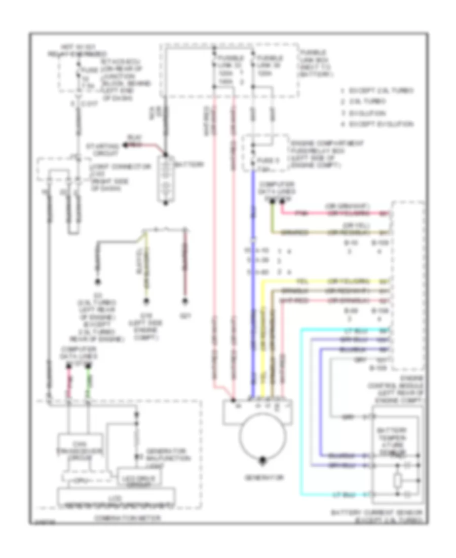
- Starting/ charging system
- To engine compartment fuse/relay box (diagram 2 of 2)
- To etacs-ecu (diagram 2 of 2)
- To ignition switch (diagram 1 of 2)
- To power window relay (diagram 2 of 2)
- Turn-signal light control circuit
Электросхема блока предохранителей и реле (2 из 2) для Mitsubishi Lancer DE 2011
Электросхема блока предохранителей и реле (2 из 2) для Mitsubishi Lancer DE 2011 - Список элементов:
- (+)
- (-)
- (hatchback) liftgate open relay
- (left side of engine compt) engine compartment fuse/relay box
- (not used)
- (on rear of junction block, behind left end of dash) etacs-ecu
- A-14x
- A-16x
- A-20x
- A/c compressor clutch relay
- Acc relay 2
- Accessory socket (front floor console)
- Accessory socket (rear floor (-) console)
- Air conditioning & cooling fans systems
- Air conditioning, anti-lock brakes, sound, cruise control, interior lights, transmissions, seats, warning, instrument cluster, headlights exterior lights, navigation & anti-theft systems
- Air conditioning, warning, door locks, headlights, interior lights, anti-theft, navigation, instrument cluster, power windows, sound, wiper/washer, exterior lights & trunk, tailgate, fuel doors systems
- Anti-lock brakes system
- Anti-theft system
- Blower relay
- C-26
- C-307
- C-309
- C-311
- C-313
- C-315
- C-317
- Cigarette lighter (front floor console)
- Condenser fan relay
- Cooling fans & air conditioning systems
- Door lock relay
- Driver's door unlock relay
- Engine controls & cruise control systems
- Except evolution
- Fan control
- Fog light relay
- From fusible link box (diagram 1 of 2)
- From ig1 relay (diagram 1 of 2)
- Fuse 1 15a
- Fuse 1 30a
- Fuse 10
- Fuse 11
- Fuse 12
- Fuse 13 (w/ discharge type headlights) 10a
- Fuse 13 (w/ halogen type headlights) 10a
- Fuse 13 15a
- Fuse 15a
- Fuse 16 10a
- Fuse 19 15a
- Fuse 2 7.5a
- Fuse 25
- Fuse 3 10a
- Fuse 3 20a
- Fuse 31 30a
- Fuse 4 10a
- Fuse 5 7.5a
- Fuse 6 (evolution)
- Fuse 6 (except evolution) 20a
- Fuse 6 20a
- Fuse 7 10a
- Fuse 7 15a
- Fuse 8 15a
- Fuse 8 7.5a
- Fuse 9 (evolution) 20a
- Fuse 9 (except evolution) 20a
- Fusible link 24 30a
- Fusible link 26 40a
- Fusible link 27 30a
- Fusible link 28 (2.0l turbo) 30a
- Fusible link 28 (except 2.0l turbo) 30a
- Fusible link 29 40a
- Fusible link 30 30a
- G14 (except evolution) (behind left kick panel)
- G18 (evolution) ( left front engine compt)
- Headlight relay (high)
- Headlight relay (low)
- Headlights system
- Horn relay
- Interior light control circuit
- Interior lights system
- Mfi relay
- Off
- Passenger's door unlock relay
- Power window relay
- Red
- Relay
- Sound & navigation systems
- Sound systems
- Sound, navigation, mirrors & transmissions systems
- Starting/ charging system
- Transmissions system
- Trunk lid open relay
- Vehicle w/ accessory socket
- Vehicle w/ cigarette lighter
БЛОКИ УПРАВЛЕНИЯ КУЗОВОМ
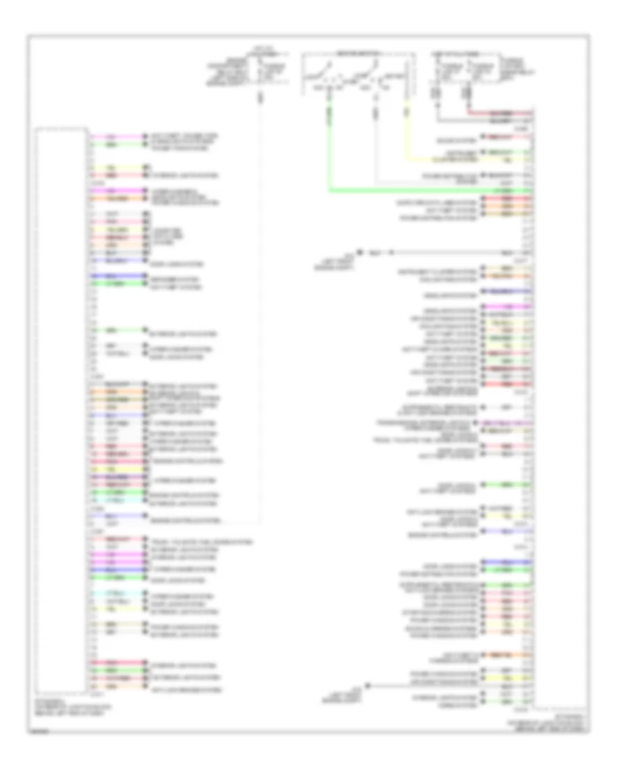
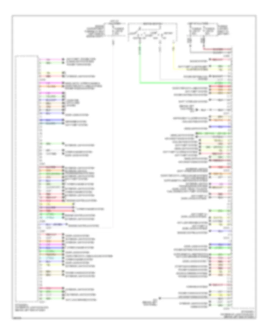
Электросхема блоков управления кузовом, эволюция для Mitsubishi Lancer DE 2011
Электросхема блоков управления кузовом, эволюция для Mitsubishi Lancer DE 2011 - Список элементов:
- Acc
- Air conditioning system
- Anti-lock brakes system
- Anti-theft & horn systems
- Anti-theft & warning systems
- Anti-theft system
- Anti-theft, power tops & headlights systems
- C-301
- C-304
- C-307
- C-309
- C-311
- C-312
- C-313
- C-314
- C-315
- C-316
- C-317
- Cluster system
- Computer data lines system
- Cooling fans system
- Defogger system
- Door locks & anti-theft systems
- Door locks & trunk, tailgate, fuel doors systems
- Door locks system
- Engine compartment relay box (left side of engine compt)
- Engine controls system
- Etacs-ecu (on rear of junction block, behind left end of dash)
- Exterior lights & shift interlock systems
- Exterior lights system
- Fusible link 30 30a
- Fusible link 34 80a
- Fusible link 37 80a
- Fusible link box (near relay box)
- G18 (left front engine compt)
- Headlights system
- Horns system
- Hot at all times
- Ignition switch
- Instrument
- Instrument cluster system
- Interior lights system
- Lock
- Pnk
- Power distribution system
- Power tops system
- Power windows system
- Red
- Sound & mirrors systems
- Sound system
- Start
- Starting/charging system
- Transmissions, exterior lights & wiper/washer systems
- Trunk, tailgate, fuel doors system
- Wiper/washer & headlights system power windows system
- Wiper/washer system
Электросхема блоков управления кузовом, кроме эволюции для Mitsubishi Lancer DE 2011
Электросхема блоков управления кузовом, кроме эволюции для Mitsubishi Lancer DE 2011 - Список элементов:
- (behind left kick panel) g14
- (or pnk)
- Acc
- Air conditioning system
- Anti-lock brakes system
- Anti-theft & door locks systems
- Anti-theft & horns systems
- Anti-theft & instrument
- Anti-theft system
- Anti-theft, power tops & headlights systems
- C-301
- C-304
- C-307
- C-309
- C-311
- C-312
- C-313
- C-314
- C-315
- C-316
- C-317
- Cluster systems
- Computer data lines & sound systems
- Computer data lines system
- Cooling fans system
- Defogger system
- Door locks system
- Door locks, trunk, tailgate, fuel doors & anti-theft systems
- Engine compartment fuse/relay box (left side of engine compt)
- Engine controls system
- Etacs-ecu (on rear of junction block, behind left end of dash)
- Exterior lights & shift interlock systems
- Exterior lights & transmissions systems
- Exterior lights system
- Fusible link 30 30a
- Fusible link 34 80a
- Fusible link 37 80a
- Fusible link box (next to battery)
- G14 (behind left kick panel)
- Headlights system
- Headlights, wiper/washer & computer data lines systems power windows system
- Horns system
- Hot at all times
- Ignition switch
- Instrument cluster system
- Interior lights system
- Lock
- Pnk
- Power distribution system
- Power tops system
- Power windows system
- Red
- Shift interlock system
- Sound & mirrors systems
- Sound system
- Start
- Starting/charging system
- Warning systems
- Wiper/washer system
БЛОКИРОВКИ СЕЛЕКТОРА СТОЯНОЧНЫЙ ТОРМОЗ
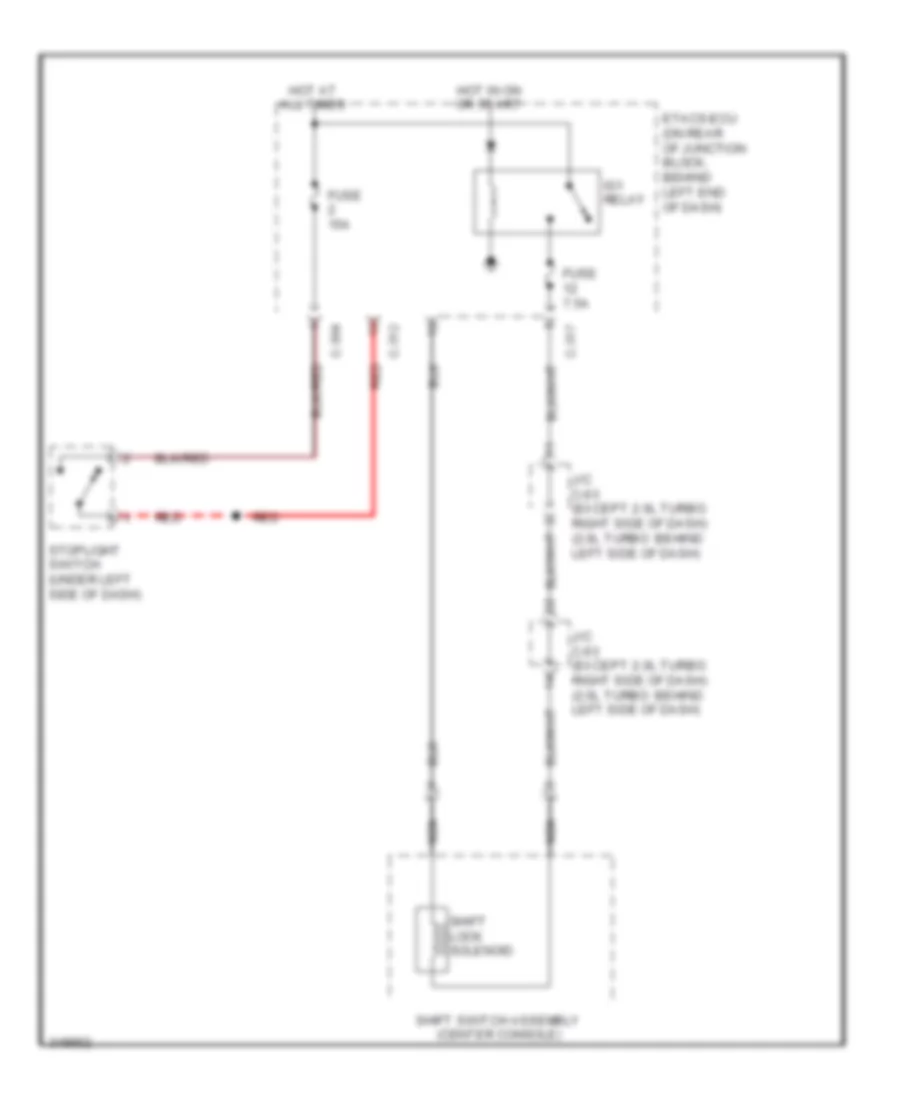
Электросхема блокировки селектора, эволюция для Mitsubishi Lancer DE 2011
Электросхема блокировки селектора, эволюция для Mitsubishi Lancer DE 2011 - Список элементов:
- (behind center of dash) g6
- C-130
- C-27
- C-304
- C-317
- C-35
- Can transceiver
- Circuit
- Combination meter
- Computer data lines system
- Cpu
- Etacs-ecu (on rear of junction block, behind left end of dash)
- Fuse 15a
- Fuse 7.5a
- High side switch
- Hot at all times
- Hot in on or start
- Ig1 relay
- J/c c-101
- Lcd shift position
- Lever position sensor (p)
- Low side switch
- Nca
- Pnk
- Red
- Shift lever (tc-sst: center console)
- Shift lever position indicator panel
- Shift lock solenoid
- Stoplight switch (under left side of dash)
Электросхема блокировки селектора, кроме эволюции, CVT для Mitsubishi Lancer DE 2011
Электросхема блокировки селектора, кроме эволюции, CVT для Mitsubishi Lancer DE 2011 - Список элементов:
- C-304
- C-312
- C-317
- Etacs-ecu (on rear of junction block, behind left end of dash)
- Fuse 15a
- Fuse 7.5a
- Hot at all times
- Hot in on or start
- Ig1 relay
- J/c c-03 (except 2.0l turbo: right side of dash) (2.0l turbo: behind left side of dash)
- Nca
- Red
- Shift lock solenoid
- Shift switch assembly (center console)
- Stoplight switch (under left side of dash)
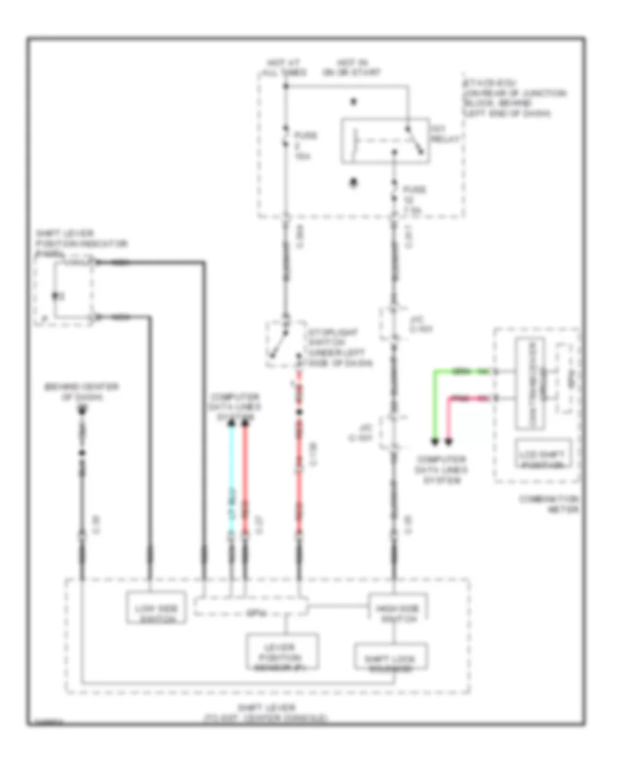
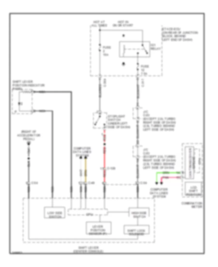
Электросхема блокировки селектора, кроме эволюции, TC-SST для Mitsubishi Lancer DE 2011
Электросхема блокировки селектора, кроме эволюции, TC-SST для Mitsubishi Lancer DE 2011 - Список элементов:
- (right of accelerator pedal) g5
- C-128
- C-304
- C-317
- C-49
- C-54
- Can transceiver
- Circuit
- Combination meter
- Computer data lines system
- Cpu
- Etacs-ecu (on rear of junction block, behind left end of dash)
- Fuse 15a
- Fuse 7.5a
- High side switch
- Hot at all times
- Hot in on or start
- Ig1 relay
- J/c c-03 (except 2.0l turbo: right side of dash) (2.0l turbo: behind left side of dash)
- Lcd shift position
- Lever position sensor (p)
- Low side switch
- Nca
- Pnk
- Red
- Shift lever (center console)
- Shift lever position indicator panel
- Shift lock solenoid
- Stoplight switch (under left side of dash)
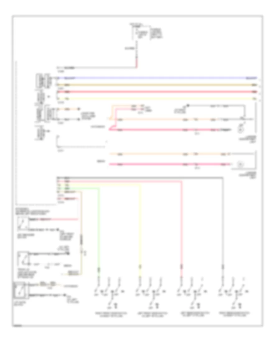
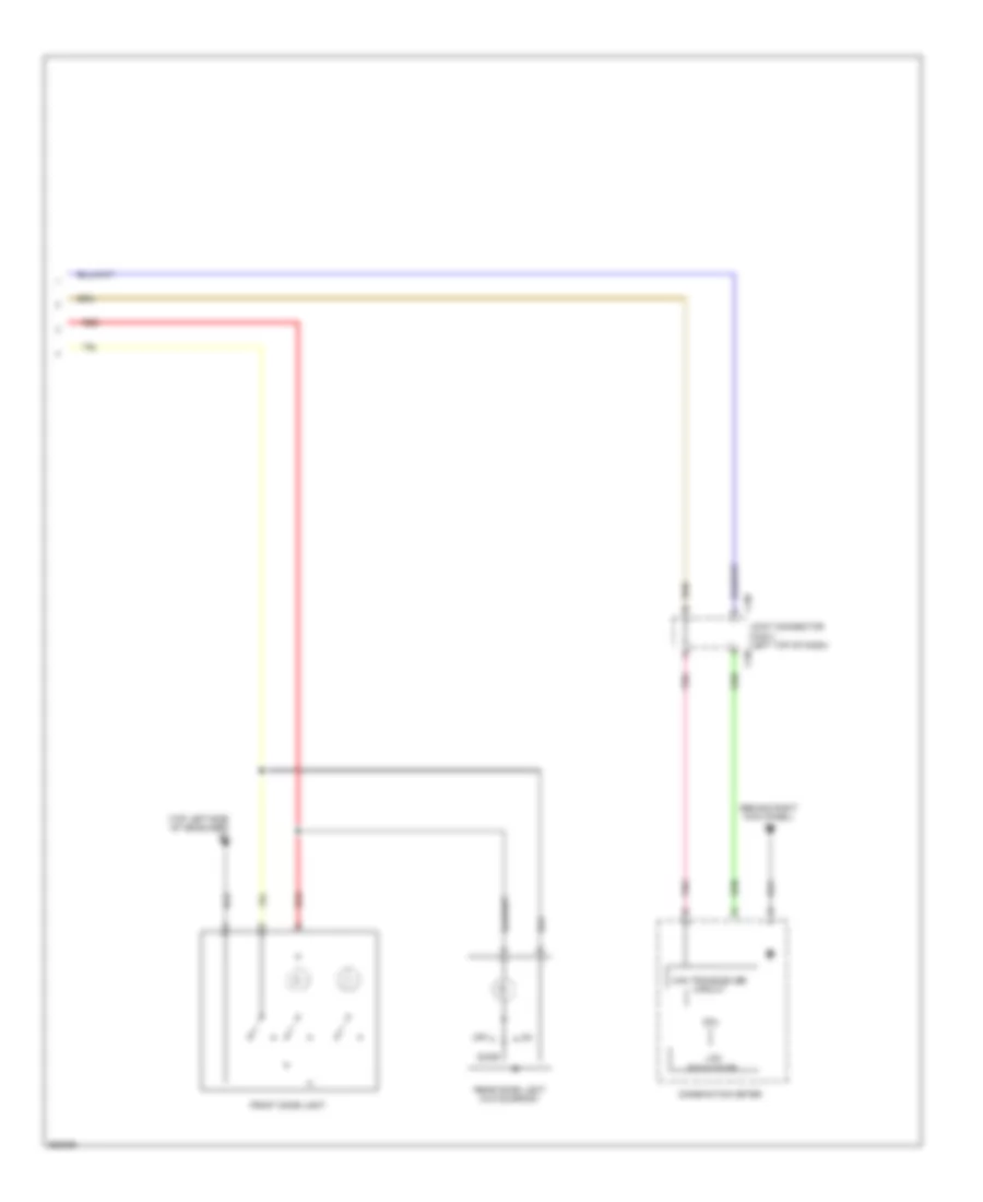
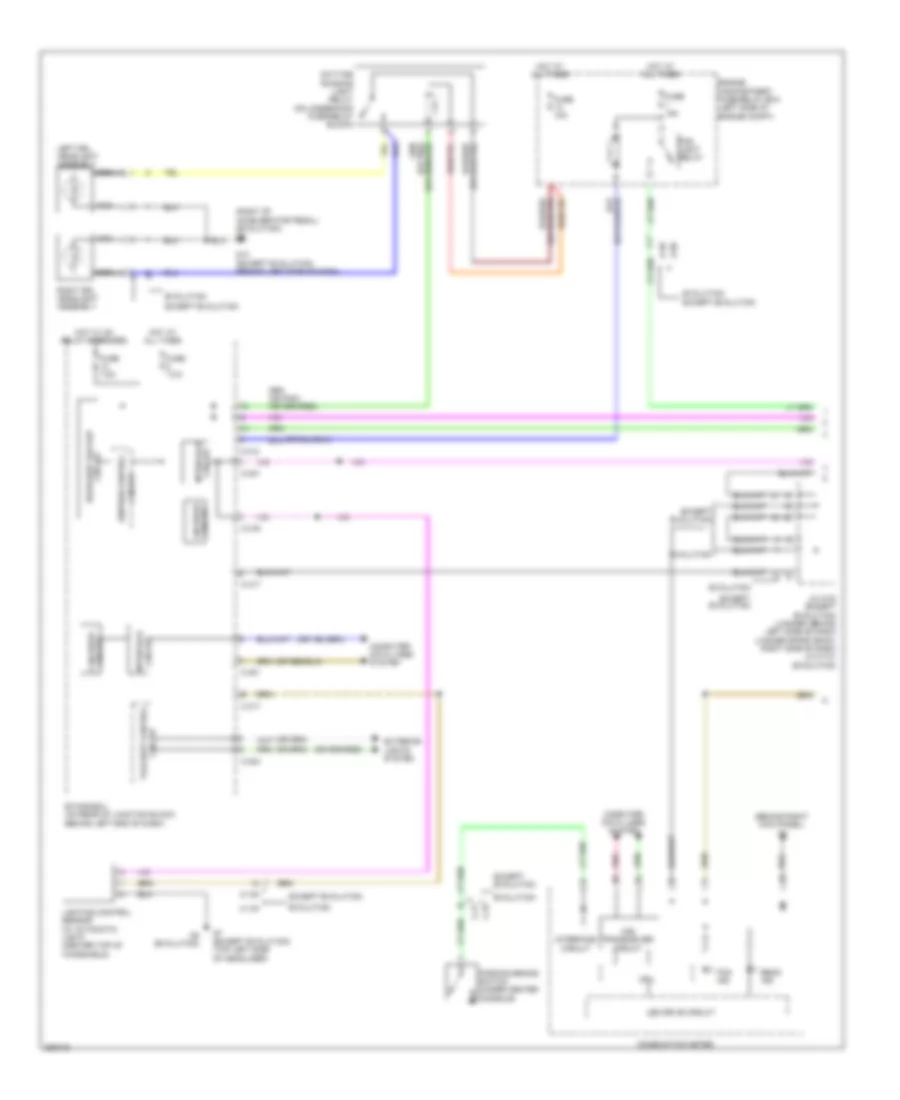
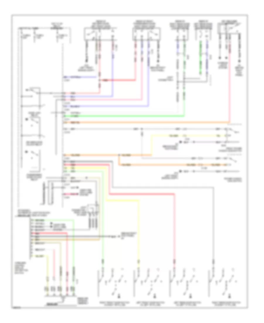
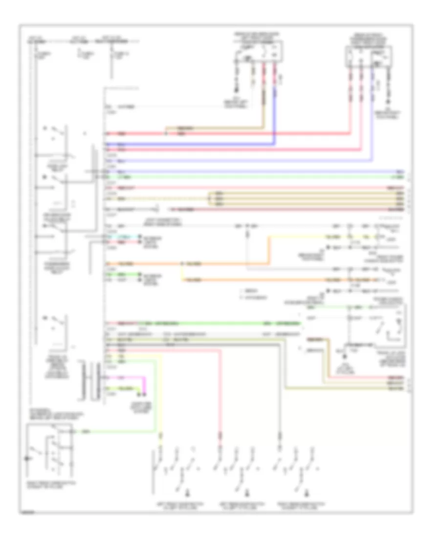
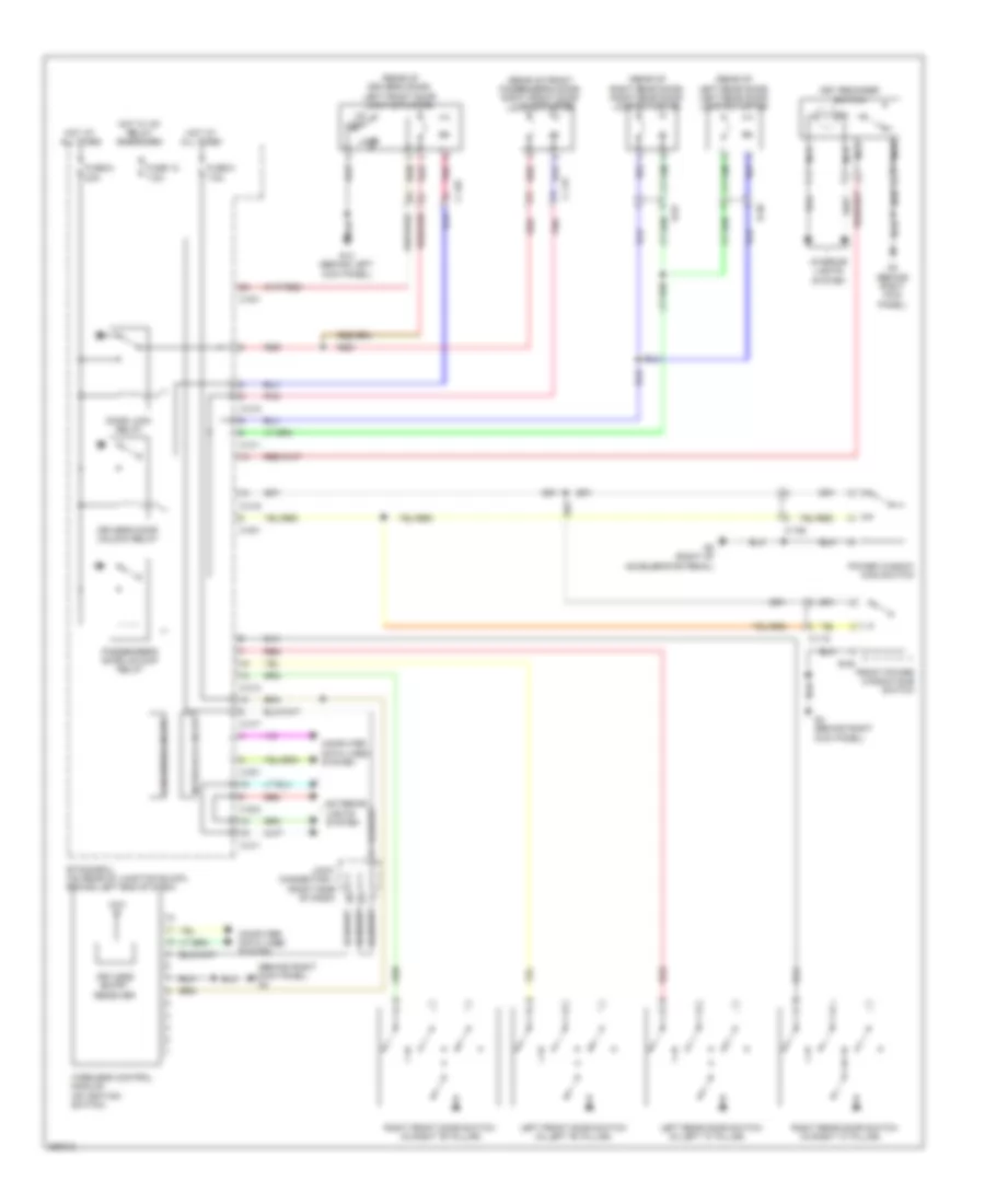
ВНЕШНЕЕ ОСВЕЩЕНИЕ
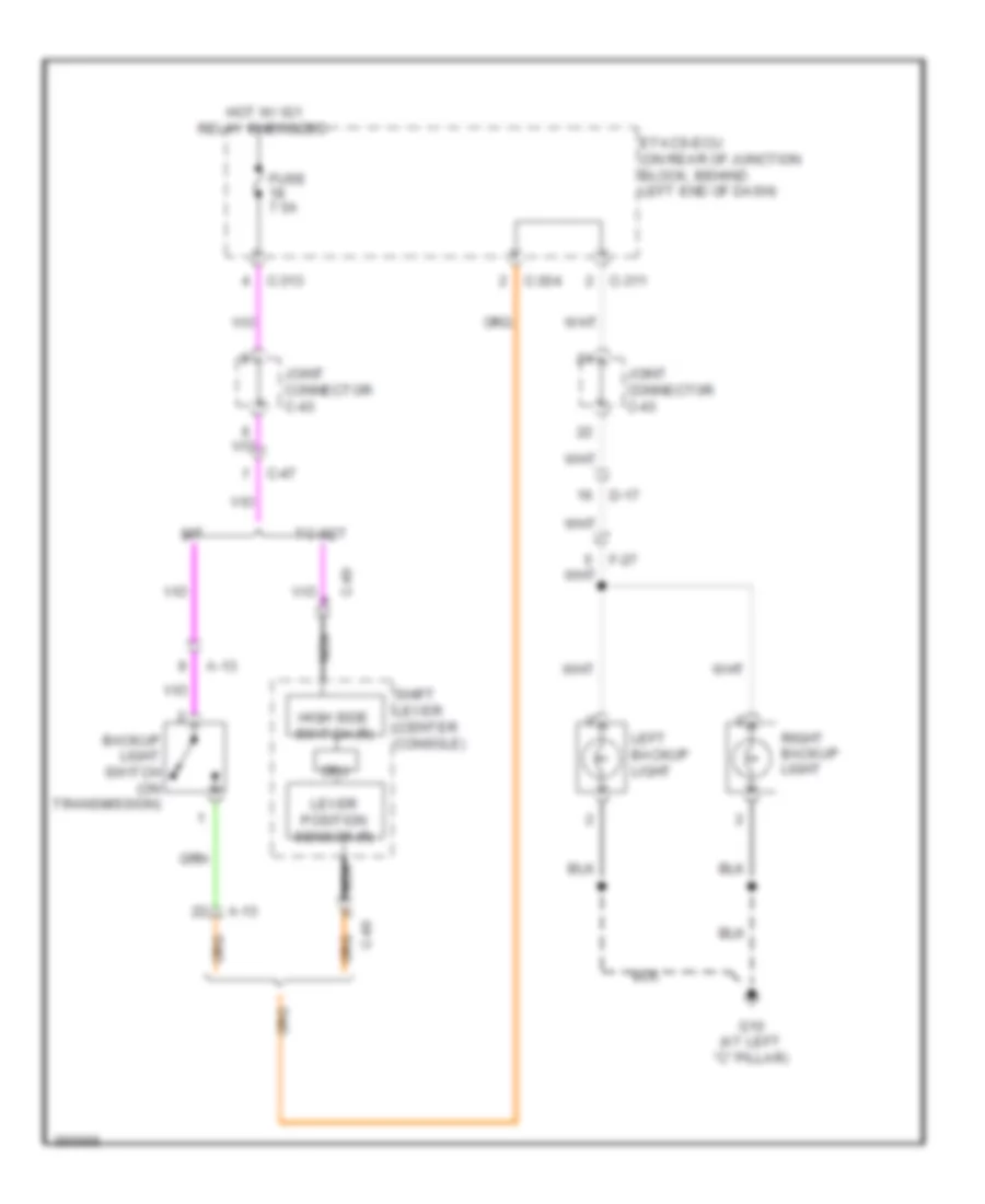
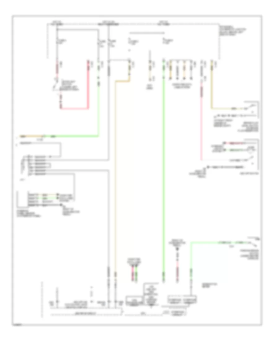
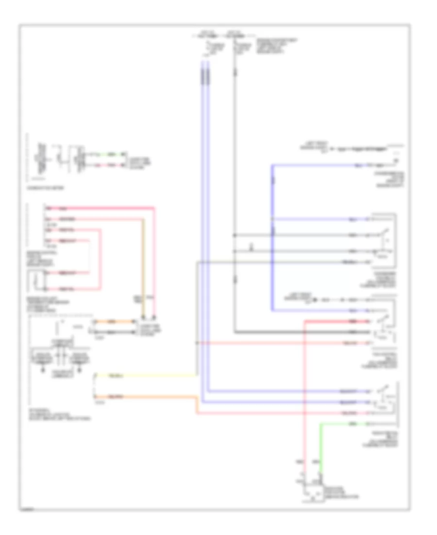
Электросхема заднего хода, эволюция для Mitsubishi Lancer DE 2011
Электросхема заднего хода, эволюция для Mitsubishi Lancer DE 2011 - Список элементов:
- A-13
- Backup light switch (on transmission)
- C-304
- C-311
- C-313
- C-47
- C-49
- Cpu
- D-17
- Etacs-ecu (on rear of junction block, behind left end of dash)
- F-27
- Fuse 7.5a
- G10 (at left "c" pillar)
- High side switch (r)
- Hot w/ ig1 relay energized
- Joint connector c-43
- Left backup light
- Lever position sensor (r)
- M/t
- Nca
- Right backup light
- Shift lever (center console)
- Tc-sst
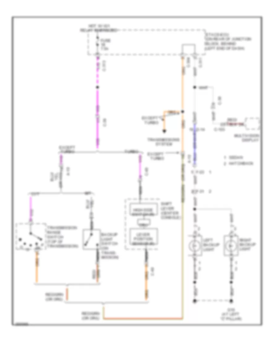
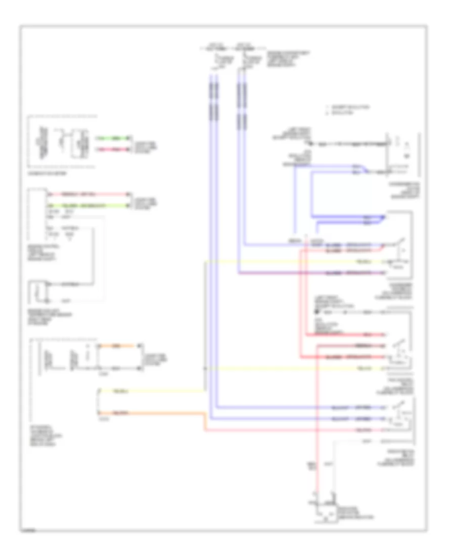
Электросхема заднего хода, кроме эволюции для Mitsubishi Lancer DE 2011
Электросхема заднего хода, кроме эволюции для Mitsubishi Lancer DE 2011 - Список элементов:
- A-10
- Backup light switch (on trans- mission)
- C-103
- C-304
- C-311
- C-313
- C-36
- C-39
- C-49
- Cpu
- Cvt
- Etacs-ecu (on rear of junction block, behind left end of dash)
- Except turbo
- F-23
- F-31
- Fuse 7.5a
- G10 (at left "c" pillar)
- Hatchback
- High side switch (r)
- Hot w/ ig1 relay energized
- Left backup light
- Lever position sensor (r)
- M/t
- Multivision display
- Nca
- Right backup light
- Sedan
- Shift lever (center console)
- Transmission range switch (top of p transmission)
- Transmissions system
- Turbo
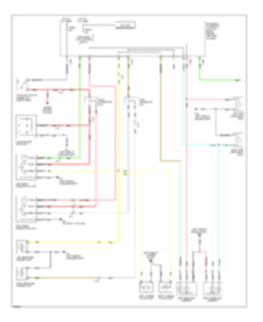
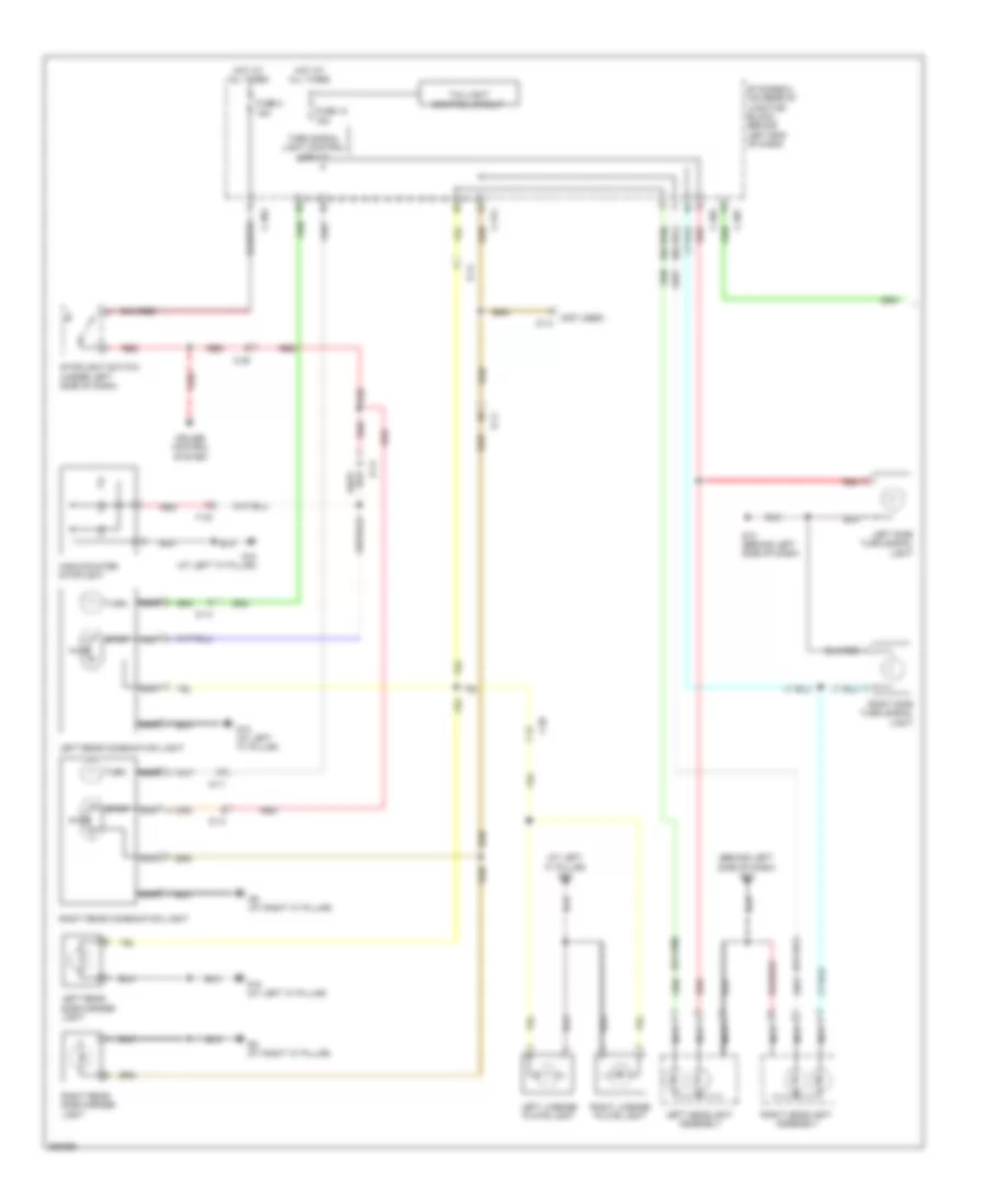
Электросхема внешнего освещения, эволюция (1 из 2) для Mitsubishi Lancer DE 2011
Электросхема внешнего освещения, эволюция (1 из 2) для Mitsubishi Lancer DE 2011 - Список элементов:
- (left side of engine compt) g19
- (left side of luggage compt) g11
- C-301
- C-304
- C-311
- C-47
- Cruise control system
- D-11
- D-17
- Etacs-ecu (on rear of junction block, behind left end of dash)
- F-17
- F-27
- Fuse 10 15a
- Fuse 2 15a
- G11 (left side of luggage compt)
- G19 (left side of engine compt)
- G9 (at right "c" pillar)
- High-mounted stoplight
- Hot at all times
- Joint connector c-43
- Left headlight assembly
- Left license plate light
- Left rear combination light
- Left rear side marker light
- Left side turn signal light
- Nca
- Red
- Right headlight assembly
- Right license plate light
- Right rear combination light
- Right rear side marker light
- Right side turn signal light
- Stop
- Stoplight switch (under left side of dash)
- Tail
- Taillight control circuit
- Turn
- Turn signal light control circuit
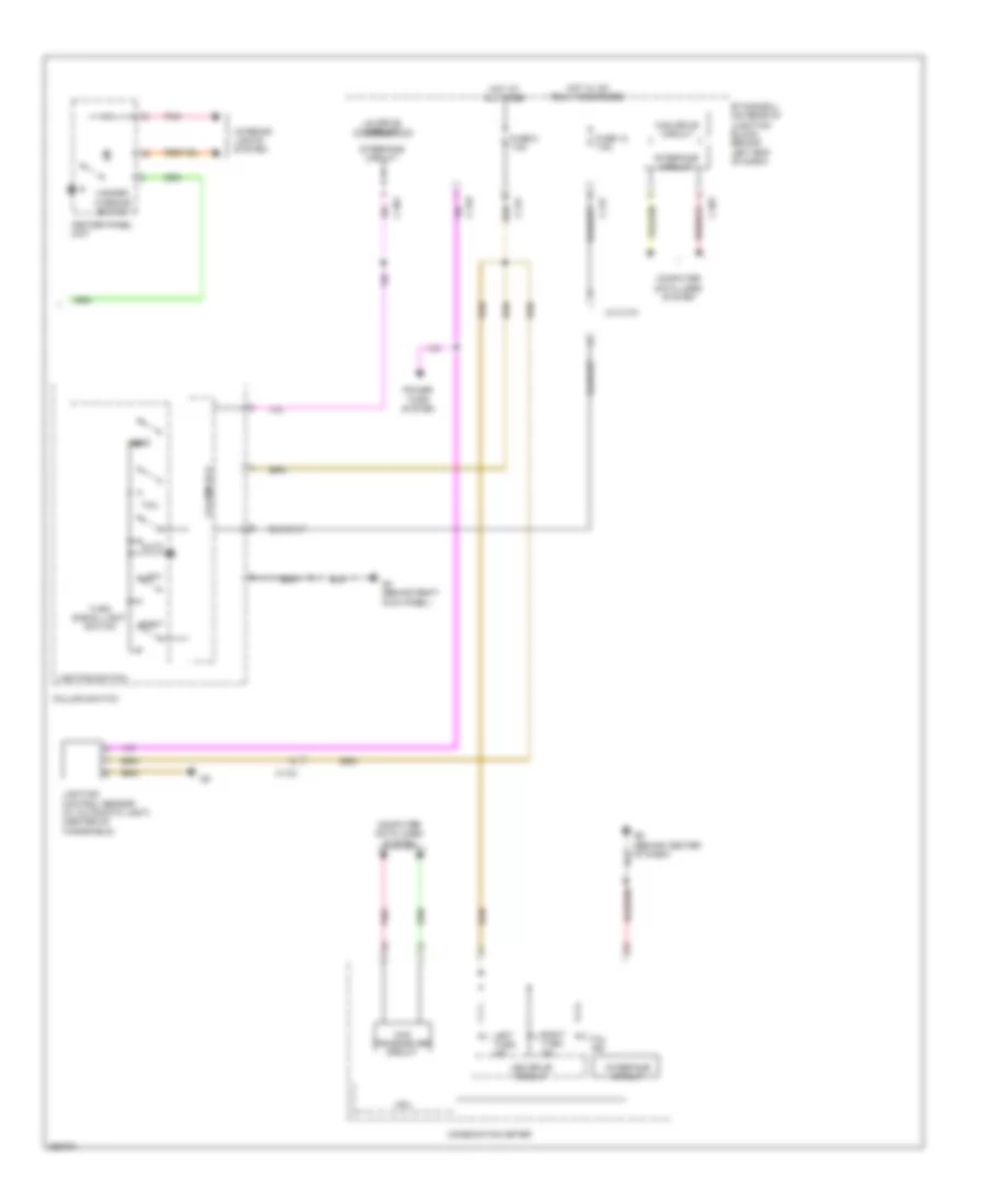
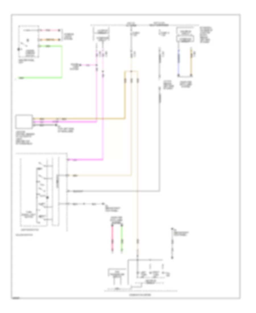
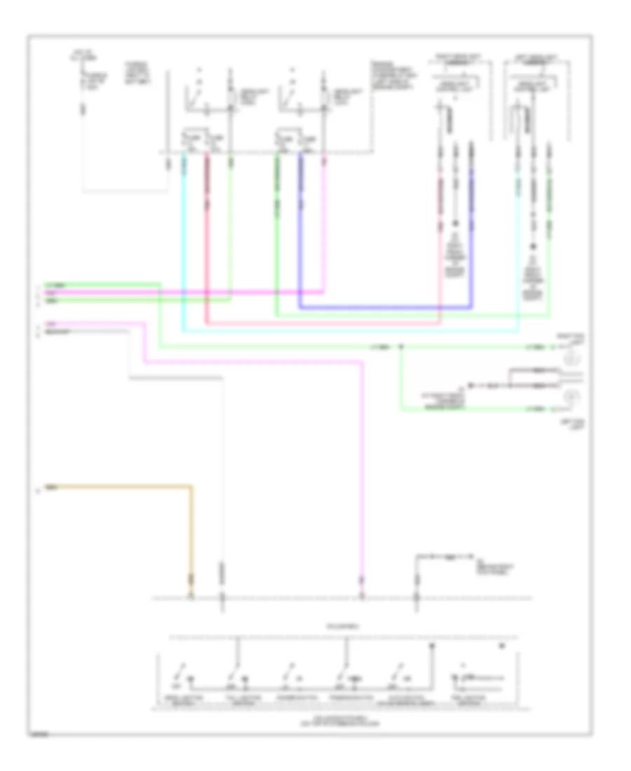
Электросхема внешнего освещения, эволюция (2 из 2) для Mitsubishi Lancer DE 2011
Электросхема внешнего освещения, эволюция (2 из 2) для Mitsubishi Lancer DE 2011 - Список элементов:
- Auto
- C-133
- C-301
- C-316
- C-317
- Can drive circuit
- Can transceiver circuit
- Center panel unit
- Column ecu
- Column switch
- Combination meter
- Computer data lines system
- Cpu
- Etacs-ecu (on rear of junction block, behind left end of dash)
- Fuse 12 7.5a
- Fuse 8 7.5a
- G4 (behind right kick panel)
- G6 (behind center of dash)
- Hazard warning switch
- Head
- Hot at all times
- Hot w/ ig1 relay energized
- Interface circuit
- Interior lights system
- J/c c-101
- Led drive circuit
- Left
- Left turn ind
- Lighting control sensor (w/ automatic light) (center of windshield)
- Lighting switch
- Lin drive circuit
- Pnk
- Power tops system
- Right
- Right turn ind
- Tail
- Tail ind
- Turn signal light switch
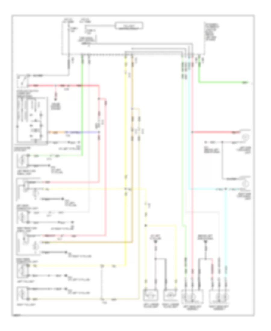
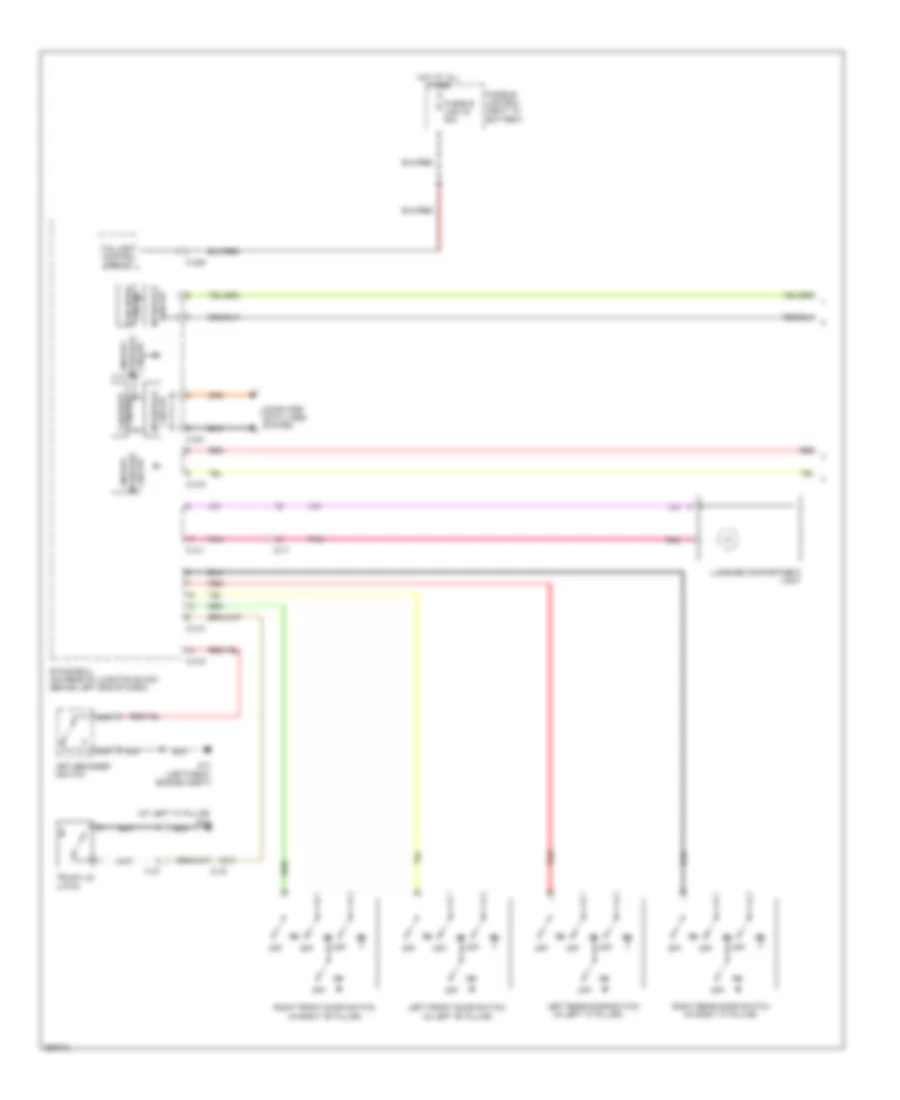
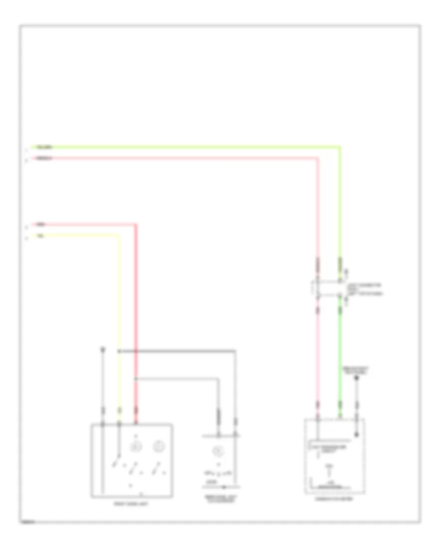
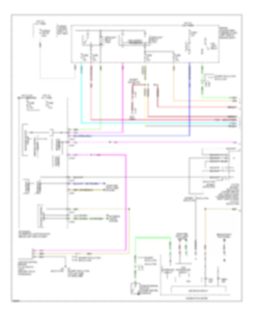
Электросхема внешнего освещения, кроме эволюции и хэтчбека (1 из 2) для Mitsubishi Lancer DE 2011
Электросхема внешнего освещения, кроме эволюции и хэтчбека (1 из 2) для Mitsubishi Lancer DE 2011 - Список элементов:
- (at left "c" pillar) g10
- (behind left side of dash) g13
- C-301
- C-304
- C-311
- C-39
- Cruise control system
- D-11
- D-14
- Etacs-ecu (on rear of junction block, behind left end of dash)
- F-15
- F-23
- F-30
- Fuse 10 15a
- Fuse 2 15a
- G10 (at left "c" pillar)
- G13 (behind left side of dash)
- G9 (at right "c" pillar)
- High-mounted stoplight
- Hot at all times
- Left headlight assembly
- Left license plate light
- Left rear combination light
- Left rear turn signal lamp
- Left side turn signal light
- Left taillight
- Nca
- Red
- Right headlight assembly
- Right license plate light
- Right rear combination light
- Right rear turn signal lamp
- Right side turn signal light
- Right taillight
- Stop
- Stoplight switch (under left side of dash)
- Taillight control circuit
- Turn signal light control circuit
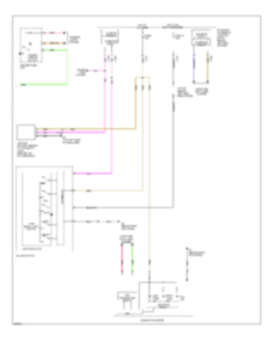
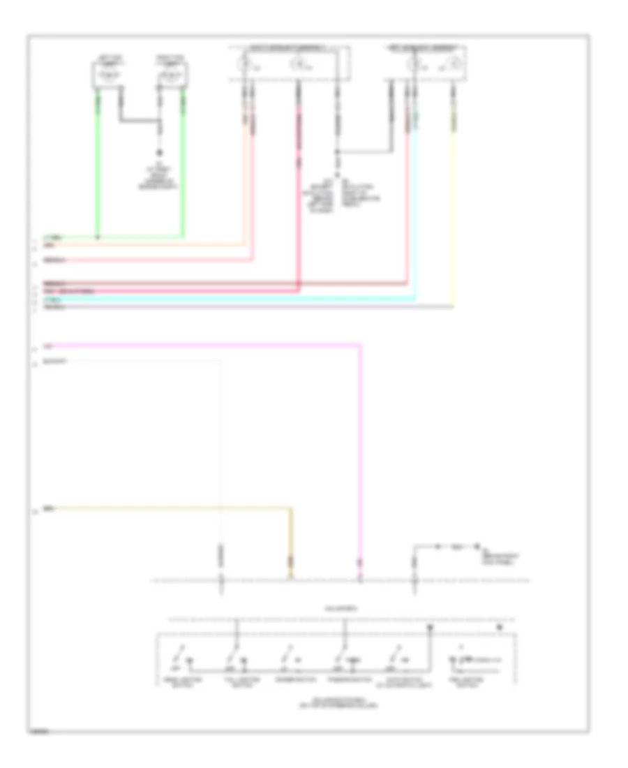
Электросхема внешнего освещения, кроме эволюции и хэтчбека (2 из 2) для Mitsubishi Lancer DE 2011
Электросхема внешнего освещения, кроме эволюции и хэтчбека (2 из 2) для Mitsubishi Lancer DE 2011 - Список элементов:
- Auto
- C-130
- C-301
- C-316
- C-317
- Can drive circuit
- Can transceiver circuit
- Center panel unit
- Column ecu
- Column switch
- Combination meter
- Computer data lines system
- Cpu
- Etacs-ecu (on rear of junction block, behind left end of dash)
- Fuse 12 7.5a
- Fuse 8 7.5a
- G4 (behind right kick panel)
- G7 (top left side of headliner)
- Hazard warning switch
- Head
- Hot at all times
- Hot w/ ig1 relay energized
- Interface circuit
- Interior lights system
- J/c c-03 (behind left side side of dash)
- Led drive circuit
- Left
- Left turn ind
- Lighting control sensor (w/ automatic light) (center top of windshield)
- Lighting switch
- Lin drive circuit
- Pnk
- Power tops system
- Right
- Right turn ind
- Tail
- Tail ind
- Turn signal light switch
Электросхема внешнего освещения, хэтчбек (1 из 2) для Mitsubishi Lancer DE 2011
Электросхема внешнего освещения, хэтчбек (1 из 2) для Mitsubishi Lancer DE 2011 - Список элементов:
- (at left "c" pillar) g10
- (behind left side of dash) g13
- (not used) d-14
- C-301
- C-304
- C-311
- C-39
- Cruise control system
- D-11
- D-14
- Etacs-ecu (on rear of junction block, behind left end of dash)
- F-23
- F-30
- Fuse 10 15a
- Fuse 2 15a
- G10 (at left "c" pillar)
- G13 (behind left side of dash)
- G9 (at right "c" pillar)
- High-mounted stoplight
- Hot at all times
- Left headlight assembly
- Left license plate light
- Left rear combination light
- Left rear side marker light
- Left side turn signal light
- Nca
- Red
- Right headlight assembly
- Right license plate light
- Right rear combination light
- Right rear side marker light
- Right side turn signal light
- Stop
- Stoplight switch (under left side of dash)
- Taillight control circuit
- Turn
- Turn signal light control circuit
Электросхема внешнего освещения, хэтчбек (2 из 2) для Mitsubishi Lancer DE 2011
Электросхема внешнего освещения, хэтчбек (2 из 2) для Mitsubishi Lancer DE 2011 - Список элементов:
- Auto
- C-130
- C-301
- C-316
- C-317
- Can drive circuit
- Can transceiver circuit
- Center panel unit
- Column ecu
- Column switch
- Combination meter
- Computer data lines system
- Cpu
- Etacs-ecu (on rear of junction block, behind left end of dash)
- Fuse 12 7.5a
- Fuse 8 7.5a
- G4 (behind right kick panel)
- G7 (top left side of headliner)
- Hazard warning switch
- Head
- Hot at all times
- Hot w/ ig1 relay energized
- Interface circuit
- Interior lights system
- J/c c-03 (behind left side of dash)
- Led drive circuit
- Left
- Left turn ind
- Lighting control sensor (w/ automatic light) (center top of windshield)
- Lighting switch
- Lin drive circuit
- Pnk
- Power tops system
- Right
- Right turn ind
- Tail
- Tail ind
- Turn signal light switch
ВНУТРЕННЕЕ ОСВЕЩЕНИЕ
Электросхема подсветки, эволюция (1 из 2) для Mitsubishi Lancer DE 2011
Электросхема подсветки, эволюция (1 из 2) для Mitsubishi Lancer DE 2011 - Список элементов:
- (at left "c" pillar) g10
- (in left "c" pillar)
- Analog
- C-301
- C-309
- C-311
- C-313
- C-315
- C-316
- Can drive circuit
- Circuit can drive
- Circuit interface
- Circuit interface analog
- Computer data lines system
- D-16
- D-17
- Etacs-ecu (on rear of junction block behind left end of dash)
- F-27
- Fusible link 34 80a
- Fusible link box (next to battery)
- G17 (left front engine compt)
- Hot at all times
- Interface circuit
- Key reminder switch
- Left front door switch (in left "b" pillar)
- Left rear door switch
- Luggage compartment light
- Nca
- Off
- Pnk
- Red
- Right front door switch (in right "b" pillar)
- Right rear door switch (in right "c" pillar)
- Taillight control circuit
- Trunk lid latch
Электросхема подсветки, эволюция (2 из 2) для Mitsubishi Lancer DE 2011
Электросхема подсветки, эволюция (2 из 2) для Mitsubishi Lancer DE 2011 - Список элементов:
- (behind right kick panel) g4
- C-105
- Can transceiver circuit
- Combination meter
- Cpu
- Door
- Front dome light
- Joint connector (can1) (left top of dash)
- Lcd (each door)
- Off
- Pnk
- Rear dome light (w/o sunroof)
- Red
Электросхема подсветки, кроме эволюции (1 из 2) для Mitsubishi Lancer DE 2011
Электросхема подсветки, кроме эволюции (1 из 2) для Mitsubishi Lancer DE 2011 - Список элементов:
- (at left "c" pillar) g10
- (in left "c" pillar)
- (not used)
- C-301
- C-309
- C-311
- C-313
- C-315
- C-316
- Can drive circuit
- Circuit
- Circuit interface
- Circuit interface analog
- Computer data lines system
- D-11
- D-14
- D-15
- Etacs-ecu (on rear of junction block, behind left end of dash)
- F-23
- F-30
- Fusible link 34 80a
- Fusible link box (next to battery)
- G10 (at left "c" pillar)
- G15 (left front of center console)
- G9 (at right "c" pillar)
- Hatchback
- Hot at all times
- Interface analog
- Interface circuit
- Key reminder switch
- Left front door switch (in left "b" pillar)
- Left rear door switch
- Lift gate switch
- Luggage compartment light
- Nca
- Off
- Pnk
- Red
- Right front door switch (in right "b" pillar)
- Right rear door switch (in right "c" pillar)
- Sedan
- Trunk lid lock actuator (center rear of trunk lid)
Электросхема подсветки, кроме эволюции (2 из 2) для Mitsubishi Lancer DE 2011
Электросхема подсветки, кроме эволюции (2 из 2) для Mitsubishi Lancer DE 2011 - Список элементов:
- (behind right kick panel) g4
- (top left side of headliner) g7
- C-06
- Can transceiver circuit
- Combination meter
- Cpu
- Door
- Front dome light
- Joint connector (can1) (left top of dash)
- Lcd (each door)
- Off
- Pnk
- Rear dome light (w/o sunroof)
- Red
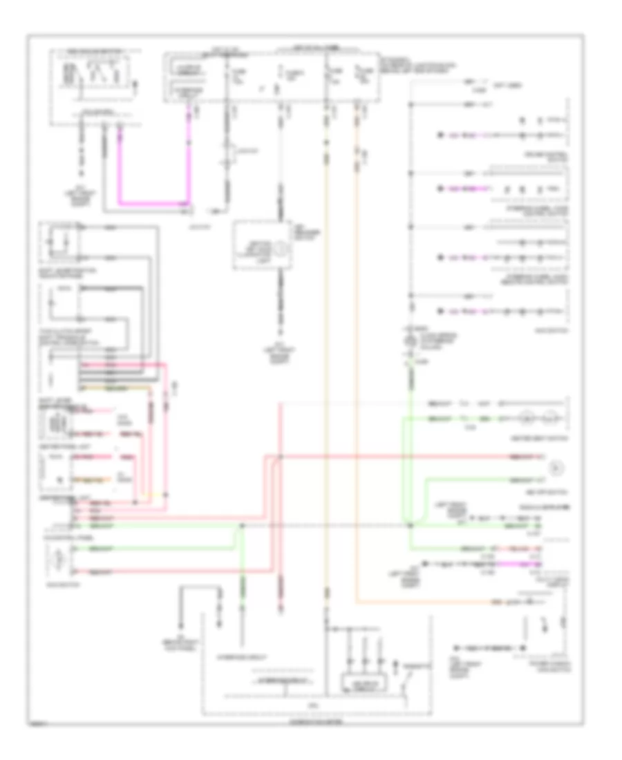
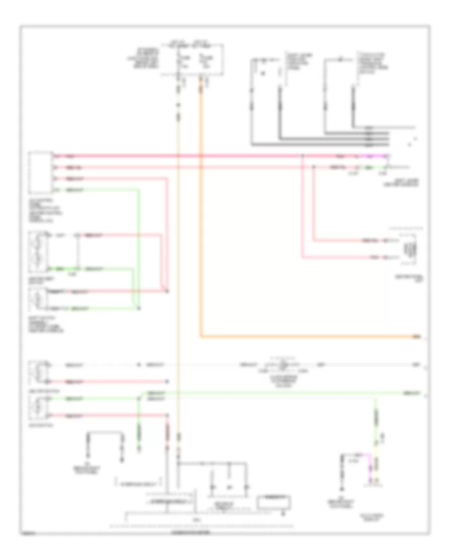
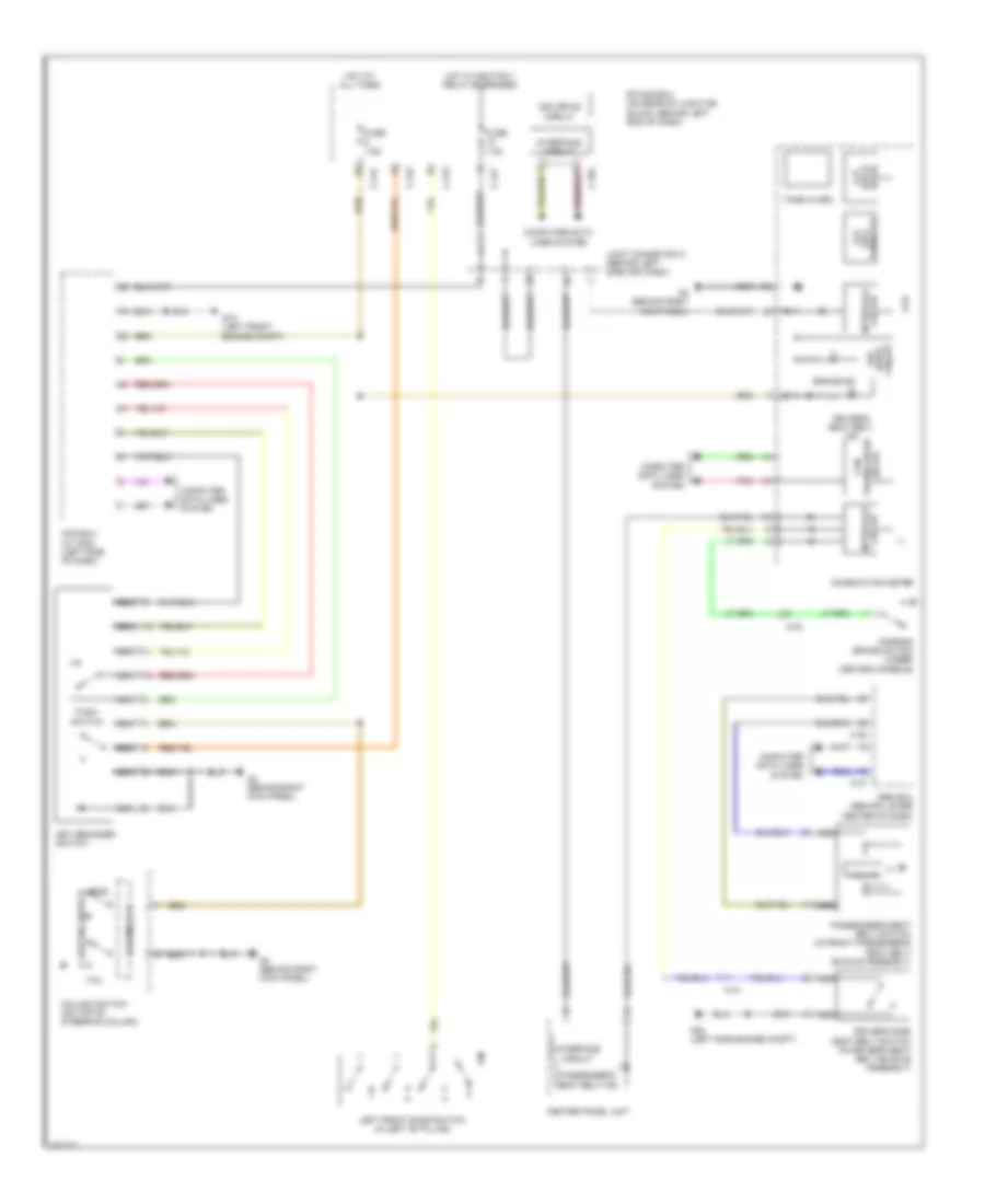
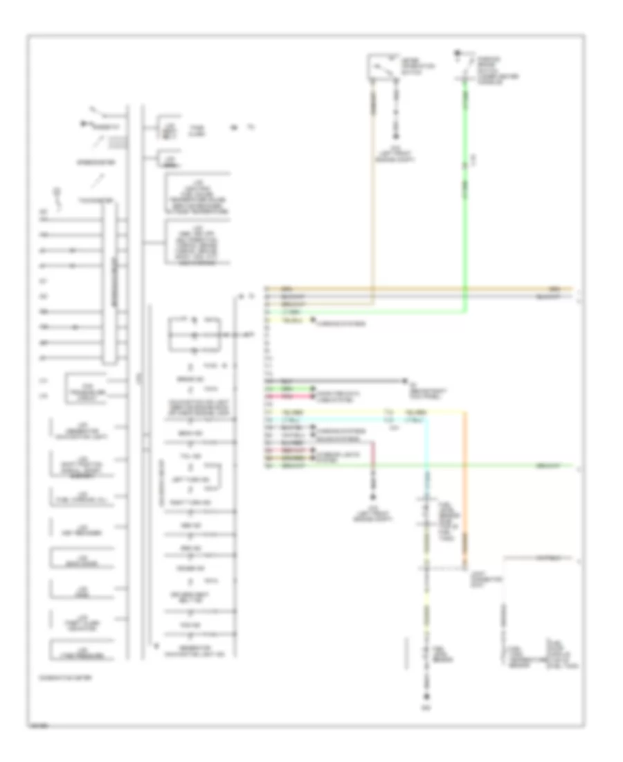
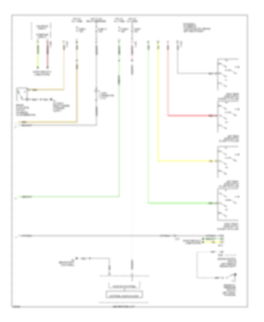
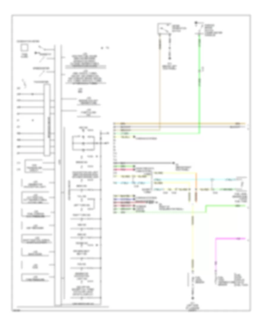
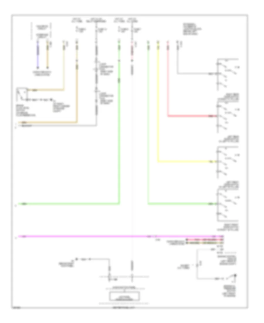
Электросхема подсветки приборов, эволюция для Mitsubishi Lancer DE 2011
Электросхема подсветки приборов, эволюция для Mitsubishi Lancer DE 2011 - Список элементов:
- (left front engine compt) g17
- (not used)
- A/c control panel
- Asc off switch
- Audio
- Awc switch
- C-106
- C-107
- C-108
- C-12
- C-128
- C-13
- C-130
- C-202
- C-205
- C-206
- C-301
- C-315
- C-317
- C-33
- Center panel unit
- Clock spring (in steering column)
- Column ecu
- Combination meter
- Cpu
- Cruise control switch
- Ecu column switch
- Etacs-ecu (on rear of junction block, behind left end of dash)
- Fuse 30a
- Fuse 7.5a
- Fuse 9 15a
- G17 (left front engine compt)
- G18 (left front engine compt)
- G4 (behind right kick panel)
- Head
- Heated seat switch
- Hot at all times
- Hot w/ ig1 relay energized
- Ignition key hole illumination light
- Interface circuit
- J/c c-101
- Key reminder switch
- Led drive circuit
- Lighting switch
- Lin drive circuit
- Multi vision display
- Nca
- Pnk
- Power window main switch
- Radio & cd player
- Rheostat
- Shift lever (center console)
- Shift lever position indicator panel
- Steering wheel audio remote control switch
- Steering wheel voice control switch
- Switch panel
- Tail
- Twin clutch sport shift transaxle control mode switch
- W/ mmcs
- W/o mmcs
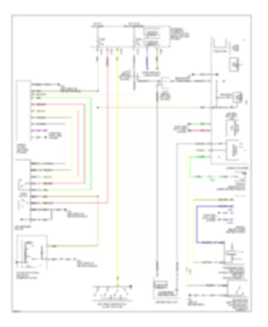
Электросхема подсветки приборов, кроме эволюции (1 из 2) для Mitsubishi Lancer DE 2011
Электросхема подсветки приборов, кроме эволюции (1 из 2) для Mitsubishi Lancer DE 2011 - Список элементов:
- A/c control panel (automatic a/c)
- Asc off switch
- Audio switch
- Awc switch
- C-103
- C-105
- C-127
- C-204
- C-205
- C-26
- C-315
- C-317
- C-49
- Center panel unit
- Clock spring (in steering column)
- Combination meter
- Cpu
- Etacs-ecu (on rear of junction block, behind left end of dash)
- Fuse 30a
- Fuse 7.5a
- G4 (behind right kick panel)
- Heated seat switch
- Heater control panel (manual a/c)
- Hot at all times
- Interface circuit
- Led drive circuit
- Multivision display
- Nca
- Panel
- Pnk
- Rheostat
- Shift lever (center console)
- Shift lever position indicator panel
- Shift switch assembly (w/ sport mode) (center console)
- Twin clutch sport shift transaxle control mode switch
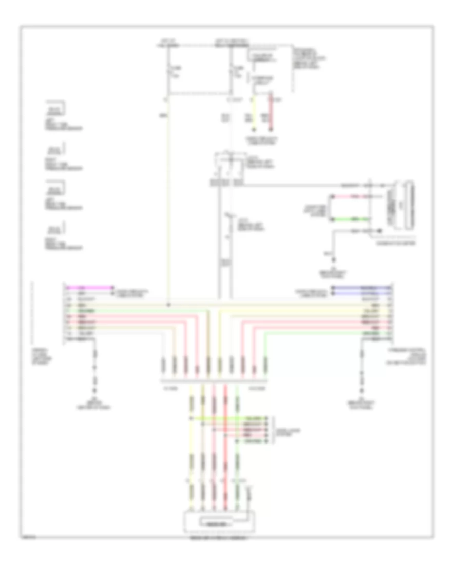
Электросхема подсветки приборов, кроме эволюции (2 из 2) для Mitsubishi Lancer DE 2011
Электросхема подсветки приборов, кроме эволюции (2 из 2) для Mitsubishi Lancer DE 2011 - Список элементов:
- (not used)
- C-104
- C-125
- C-209
- C-301
- C-315
- C-317
- Column ecu
- Column switch (on top of steering column)
- Cpu
- Cruise control switch
- Dimmer
- Etacs-ecu (on rear of junction block, behind left end of dash)
- Fuse 15a
- Fuse 7.5a
- G14 (behind left kick panel)
- G15 (left front of center console)
- Head
- Hot at all times
- Hot w/ ig1 relay energized
- Ignition key hole illumination light
- Interface circuit
- J/c c-03
- Key reminder switch
- Lighting switch
- Lin drive circuit
- Nca
- Power window main switch
- Radio & cd player
- Steering wheel audio remote control switch
- Steering wheel voice control switch
- Tail
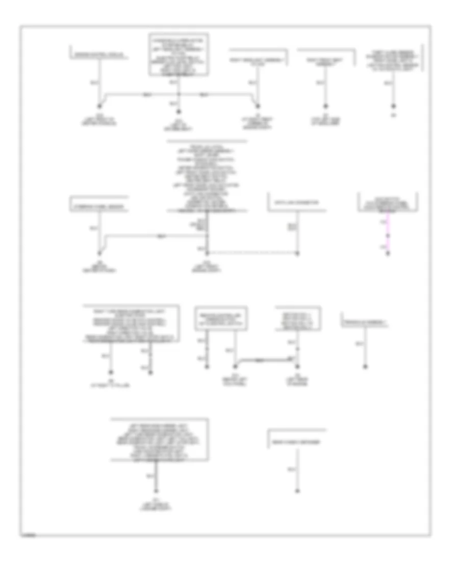
ЗАЗЕМЛЕНИЕ ПОДКЛЮЧЕНИЕ МАССЫ
Электросхема подключение массы заземления, эволюция (1 из 2) для Mitsubishi Lancer DE 2011
Электросхема подключение массы заземления, эволюция (1 из 2) для Mitsubishi Lancer DE 2011 - Список элементов:
- (w/ keyless entry)
- Awc switch (w/o steering wheel audio remote control switch)
- Data link connector
- Engine control module
- G1 (at right front corner of engine compt)
- G11 (left side of luggage compt)
- G12 (left of drivers seat)
- G14 (behind left kick panel)
- G15 (left front of center console)
- G18 (left front engine compt)
- G3 (left rear of engine)
- G6 (behind center of dash)
- G7 (top left side of headliner)
- G9 (at right "c" pillar)
- Ignition coil 1, ignition coil 2, ignition coil 3 & ignition coil 4
- Kos ecu
- Left rear side marker light, right rear side marker light, left turn rear combination light, rear combination light (left taillight), rear combination light (left stoplight), trunk lid opener switch, high mounted stoplight, right license plate light & left license plate light
- Rear window defogger
- Remote controlled mirror switch, 1st & 2nd rail switch
- Right front seat assembly
- Right headlight assembly (w/ hid)
- Right turn rear combination light, electric pump, proportioning valve (ayc control), proportioning valve (acd control), left direction valve, right direction valve, rear combination light (right stoplight) & rear combination light (right taillight)
- Steering wheel sensor
- Theft alarm sensor, sunroof motor assembly, front dome light & lighting control sensor (w/ automatic light)
- Transaxle assembly
- Trunk lid latch, left door mirror assembly, shift lever, power window main switch, etacs ecu, meter information switch, left front door lock switch, heated seat switch, heated seat relay, left front door lock actuator, accessory socket, data link connector, asc off switch, cigarette lighter, combination meter &
- Windshield wiper motor, starter relay, left headlight assembly (w/ hid), electric pump relay brake fluid level switch, left fog light, right fog light & injector relay
Электросхема подключение массы заземления, эволюция (2 из 2) для Mitsubishi Lancer DE 2011
Электросхема подключение массы заземления, эволюция (2 из 2) для Mitsubishi Lancer DE 2011 - Список элементов:
- (if equipped),
- (w/o keyless entry),
- Asc-ecu
- Awc-ecu
- Battery
- Data link connector & combination meter
- Driver's side seat belt switch, audio amplifier, left heated seat assembly, right heated seat assembly & audio amplifier
- Engine control module
- Engine control module, condenser fan motor & fan control relay
- Fuel pump module
- G10 (at left "c" pillar)
- G13 (behind left side of dash)
- G16 (rear of engine compt)
- G17 (left front engine compt)
- G19 (left side of engine compt)
- G2 (rear of engine)
- G21
- G22
- G2o (left side of engine compt)
- G4 (behind right kick panel)
- G5 (right of accelerator pedal)
- Key reminder switch, a/c control panel, a/c-ecu, kos-ecu, power transistor, radio & cd player, center panel unit,
- Left backup light & right backup light
- Right door miror assembly, paddle shift switch, multivision display, right front door lock switch, hands free module, column switch,
- Right front door lock actuator, front power window sub switch & can box unit
- Satellite radio tuner
- Spare connector (for navigation unit), spare connector (for audio), spare connector (for handsfree module), usb box,
- Srs ecu
- Theft alarm siren, hood switch, remote controlled mirror switch, headlight assembly (left position light), headlight assembly (right position light), headlight assembly (left turn light), headlight assembly (right turn light), shift lever, left side turn signal light, right side turn signal light, stoplight switch, clutch pedal position switch (m/t), left drl headlight assembly (w/ hid), right drl headlight assembly (w/ hid), left headlight assembly (w/o hid) & right headlight assembly (w/o hid)
- Trunk lid latch
- Wireless control module
Электросхема подключение массы заземления, кроме эволюции для Mitsubishi Lancer DE 2011
Электросхема подключение массы заземления, кроме эволюции для Mitsubishi Lancer DE 2011 - Список элементов:
- (hatchback)
- (hatchback),
- (m/t),
- (w/ halogen type),
- (w/drl),
- 2.0l & 2.4l
- 2.0l turbo
- Audio amplifier, driver's side seat belt switch, left heated seat assembly & right heated seat assembly
- Awc-ecu
- Battery
- Combination meter & srs-ecu
- Control module, asc-ecu & abs-ecu
- Data link connector
- Electric power steering ecu (2.0l)
- Engine control module
- Engine control module, condenser fan motor & fan control relay
- Fuel pump module
- G1 (at right front corner of engine compt)
- G10 (at left "c" pillar)
- G11 (left side of luggage compt)
- G12 (left of drivers seat)
- G13 (behind left side of dash)
- G14 (behind left kick panel)
- G15 (left front of center console)
- G16 (rear of engine compt)
- G17 (left front engine compt)
- G18 (left front engine compt)
- G19 (left side of engine compt)
- G2 (except 2.0l (turbo): right rear of engine) (2.0l (turbo): rear of engine)
- G20 (left side of engine compt)
- G21 (wagon: on liftgate)
- G22
- G3 (2.0l (turbo): left rear of engine) (except 2.0l (turbo): rear of engine)
- G4 (behind right kick panel)
- G5 (right of accelerator pedal)
- G6 (behind center of dash)
- G7 (top left side of headliner)
- G9 (at right "c" pillar)
- Headlight assembly (left turn signal light), headlight assembly (right turn signal light), right side turn signal light, stop light switch, theft alarm siren, clutch pedal position switch headlight assembly (left position light), left headlight assembly headlight assembly (right position light), right headlight assembly left side turn signal light & shift lever
- Heated seat switch, asc off switch, combination meter, accessory socket (rear floor console), accessory socket (front floor console), cigarette lighter (front floor console), data link connector, left front door lock actuator, left front door lock switch, headlight leveling switch, left door mirror assembly, heated seat relay, left front door lock/unlock sensor, meter information switch, etacs-ecu, power window main switch, remote controlled mirror switch, shift switch assembly & shift lever
- Heater control unit, usb box, spare connector (for hand sfree module) spare connector (for navigation unit), can box unit, a/c control panel, a/c ecu, power transistor, satellite radio tuner, center panel unit, multivision display, radio & cd player, key reminder switch, right front door lock actuator, front power window sub switch, wireless control module (w/o keyless entry), kos-ecu (if equipped), column switch, hands free module, spare connector (for satellite radio turner) heater control panel (manual a/c), a/c control panel (automatic a/c), right door mirror assembly, right front door lock/unlock switch, paddle shift switch
- Ignition coil 1, ignition coil 2, ignition coil 3 & ignition coil 4
- Left headlight assembly (w/ discharge type), electric pump relay, brake fluid level switch, left fog light, right fog light, cvt control relay, injector relay, starter relay, windshield wiper motor & hood latch switch
- Left headlight assembly right headlight assembly
- Left license plate light, right license plate light, right taillight & left taillight
- Liftgate lock release handle
- Liftgate switch
- Luggage compartment light (hatchback), electric pump, proportioning valve, right rear combination turn signal light, right rear combination stop light & right rear combination taillight/side marker light
- Rear window defogger
- Rear wiper motor,
- Right backup light, left backup light, high-mounted stop light,
- Right front seat assembly
- Right headlight assembly (w/ discharge type)
- Steering wheel sensor
- Theft alarm sensor, lighting control sensor (w/ automatic light), front dome light & sunroof motor assembly
- Transaxle
- Transaxle assembly
- Trunk lid opener, left rear combination turn-signal light, left rear combination stop light, trunk lid lock actuator & left rear combination taillight/side marker light
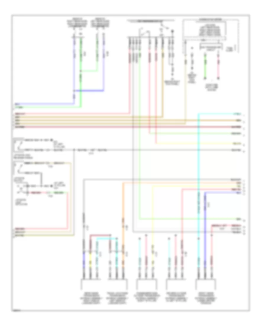
Звуковой сигнал Гудок
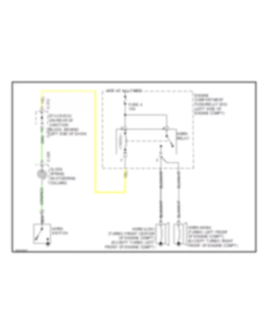
Электросхема звукового сигнал Гудка для Mitsubishi Lancer DE 2011
Электросхема звукового сигнал Гудка для Mitsubishi Lancer DE 2011 - Список элементов:
- C-205
- C-312
- C-315
- Clock spring (in steering column)
- Engine compartment fuse/relay box (left side of engine compt)
- Etacs-ecu (on rear of junction block, behind left end of dash)
- Fuse 4 10a
- Horn (high) (turbo: left front of engine compt) (except turbo: right front of engine compt)
- Horn (low) (turbo: front center of engine compt) (except turbo: left front of engine compt)
- Horn relay
- Horn switch
- Hot at all times
- Nca
Магнитола Мультимедия
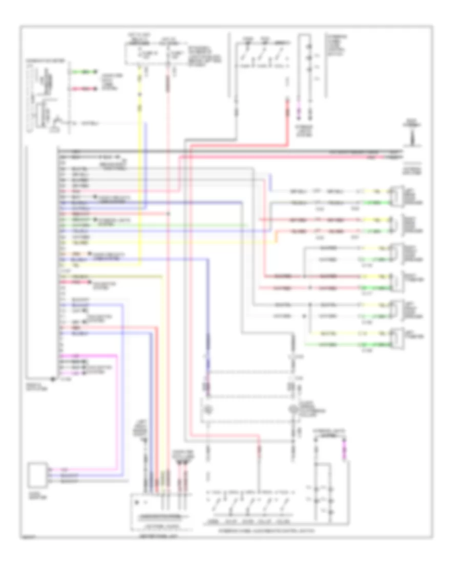
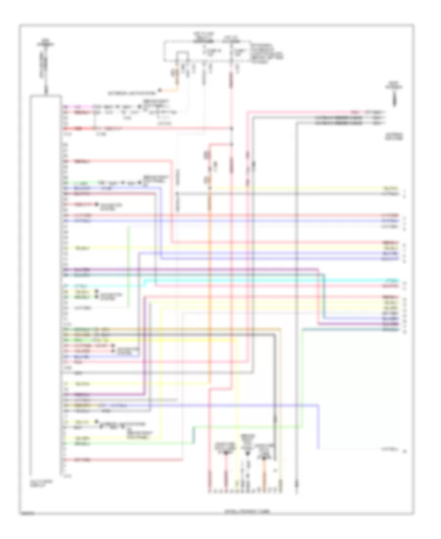
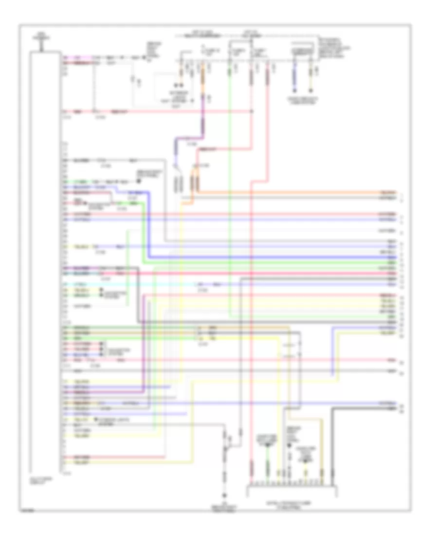
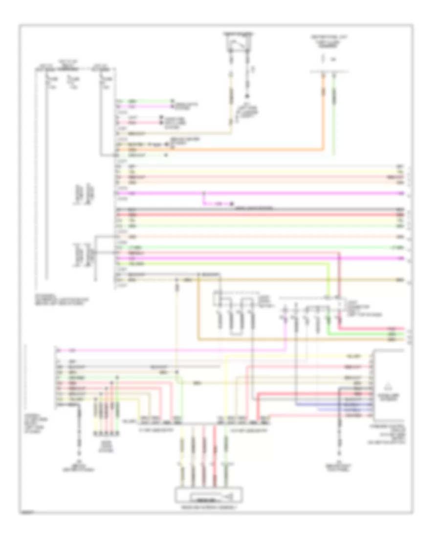
Электросхема магнитолы, Эволюция С Мультисистема связи (1 из 3) для Mitsubishi Lancer DE 2011
Электросхема магнитолы, Эволюция С Мультисистема связи (1 из 3) для Mitsubishi Lancer DE 2011 - Список элементов:
- (antenna feeder cable)
- (behind right kick panel) g4
- Antenna amplifier
- C-09
- C-10
- C-106
- C-108
- C-110
- C-12
- C-13
- C-304
- C-311
- C-315
- C-317
- C-42
- C108
- Cable) (gps antenna
- Computer data lines system
- Etacs-ecu (on rear of junction block, behind left end of dash)
- Exterior lights system
- Fuse 16 10a
- Fuse 7 15a
- G4 (behind right kick panel)
- Gps antenna
- Hot at all times
- Hot w/ acc relay 2 energized
- Interior lights system
- J/c c-43
- Multivision display
- Navigation system
- Nca
- Pnk
- Red
- Roof antenna
- Satellite radio tuner
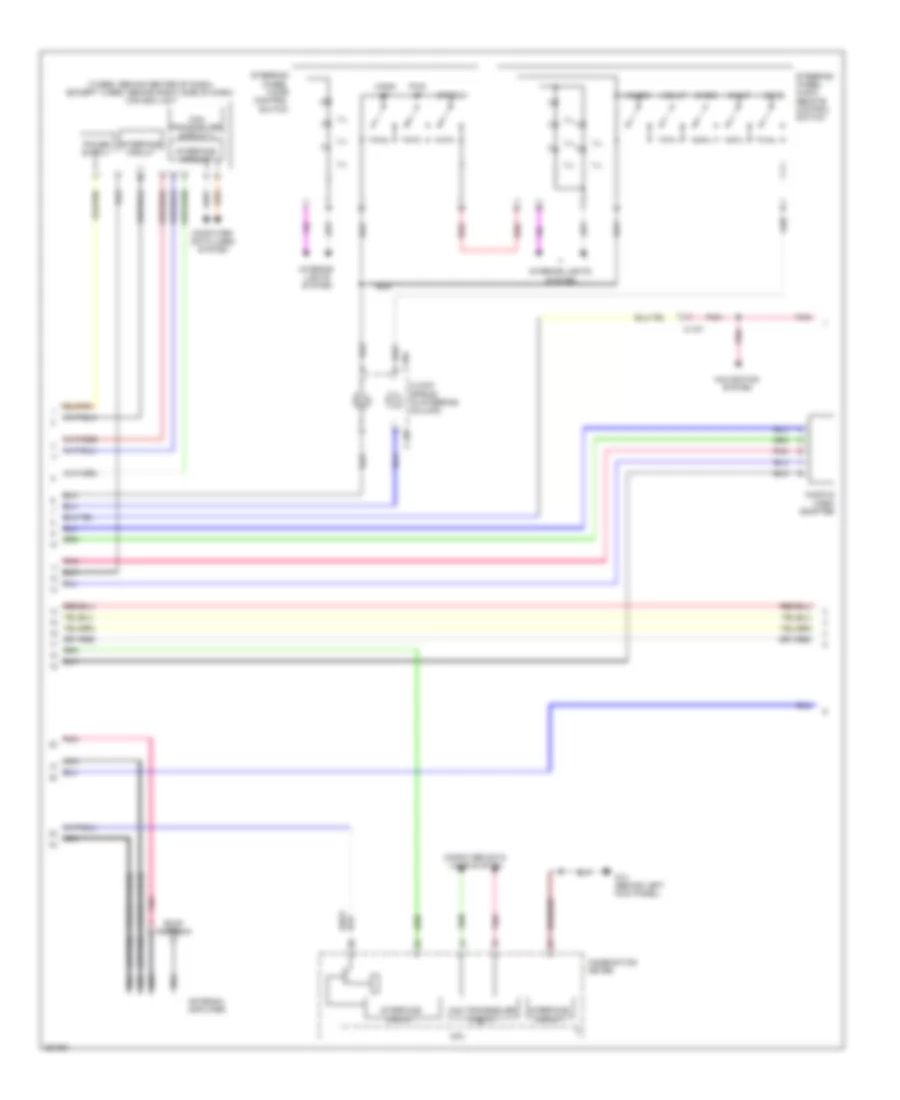
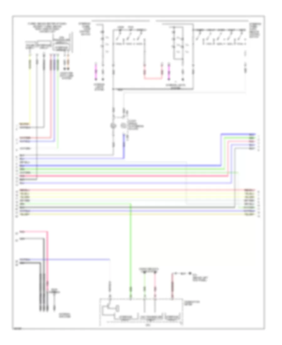
Электросхема магнитолы, Эволюция С Мультисистема связи (2 из 3) для Mitsubishi Lancer DE 2011
Электросхема магнитолы, Эволюция С Мультисистема связи (2 из 3) для Mitsubishi Lancer DE 2011 - Список элементов:
- (turbo: behind center of dash) (except turbo: behind right side of dash) can box unit
- Audio & video adapter
- C-106
- C-108
- C-110
- C-202
- C-205
- C-32
- Can transceiver circuit
- Ch dn
- Ch up
- Circuit interface
- Circuit transceiver can
- Clock spring (in steering column)
- Combination meter
- Computer data lines system
- Cpu
- G4 (behind right kick panel)
- Hang up
- Ill
- Interface circuit
- Interior lights system
- Mode
- Pick up
- Pnk
- Red
- Speech
- Steering wheel audio remote control switch
- Steering wheel voice control switch
- Vol dn
- Vol up
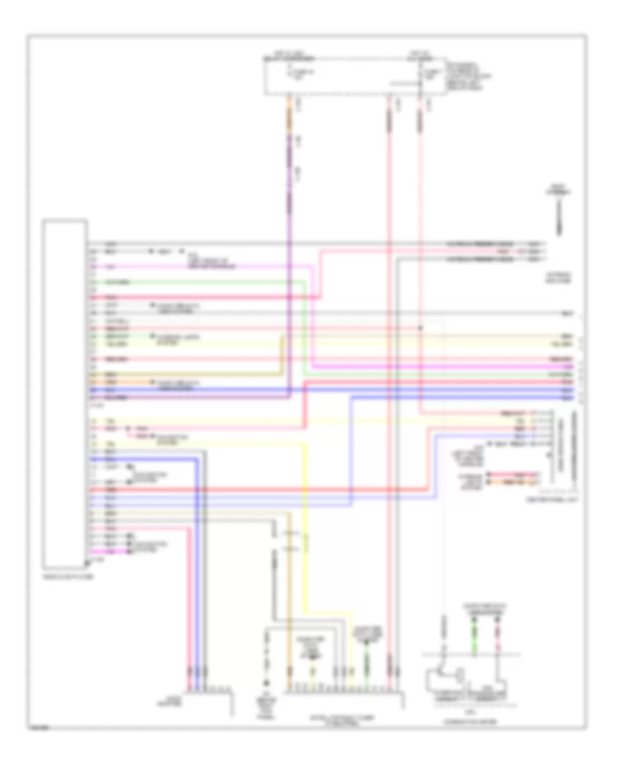
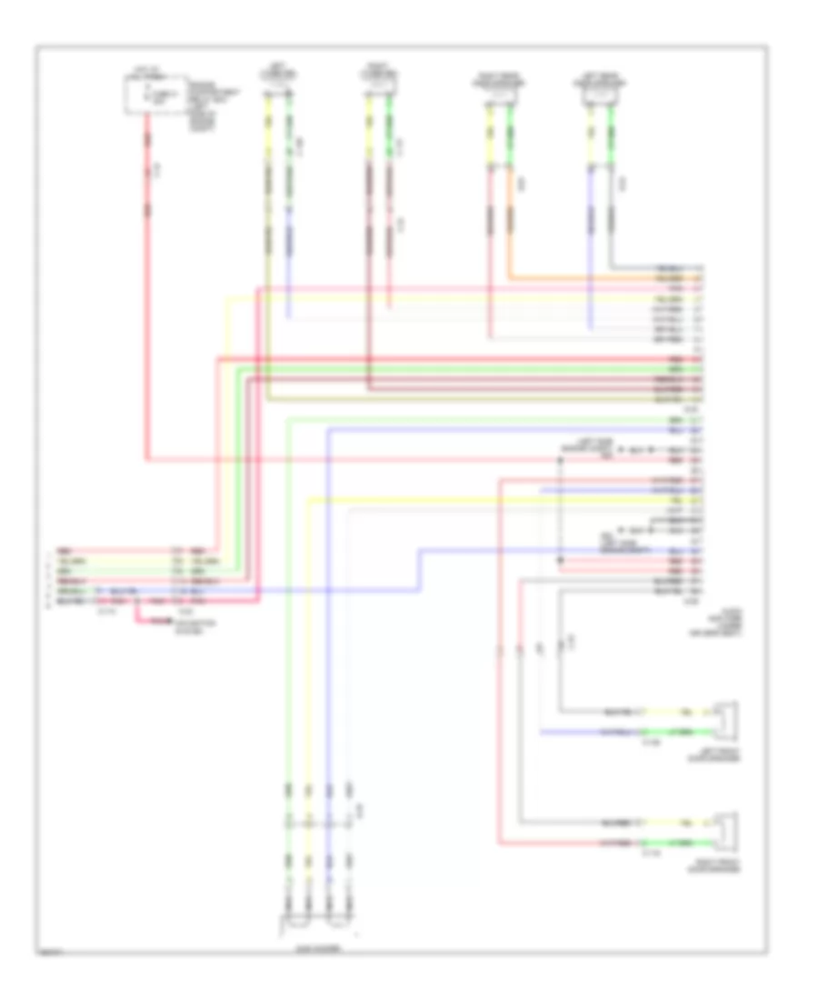
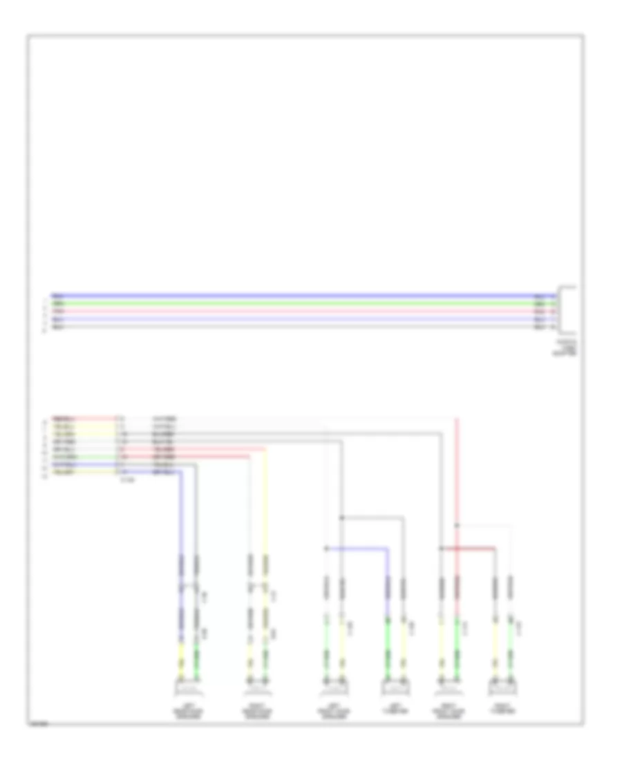
Электросхема магнитолы, Эволюция С Мультисистема связи (3 из 3) для Mitsubishi Lancer DE 2011
Электросхема магнитолы, Эволюция С Мультисистема связи (3 из 3) для Mitsubishi Lancer DE 2011 - Список элементов:
- (left side engine compt) g20
- Audio amplifier (under driver's seat)
- C-110
- C-116
- C-117
- C-128
- C-129
- C-23
- C-24
- C-47
- D-01
- D-16
- D-24
- D-29
- D-30
- Engine compartment relay box (left side of engine compt)
- Fuse 31 30a
- G20 (left side engine compt)
- Hot at all times
- Left front door speaker
- Left rear door speaker
- Left tweeter
- Navigation system
- Nca
- Pnk
- Red
- Right front door speaker
- Right rear door speaker
- Right tweeter
- Sub woofer
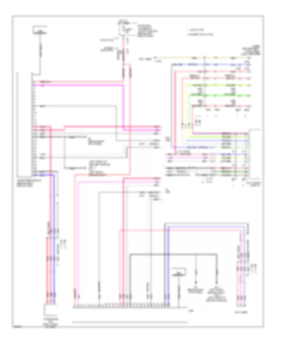
Электросхема магнитолы, Эволюция без Мультисистема связи С Усилитель (1 из 2) для Mitsubishi Lancer DE 2011
Электросхема магнитолы, Эволюция без Мультисистема связи С Усилитель (1 из 2) для Mitsubishi Lancer DE 2011 - Список элементов:
- (antenna feeder cable)
- (behind right kick panel) g4
- Antenna amplifier
- Audio adapter
- Audio switch panel
- C-107
- C-109
- C-315
- C-317
- Center panel unit
- Computer data lines system
- Etacs-ecu (on rear of junction block, behind left end of dash)
- Fuse 16 10a
- Fuse 7 15a
- G17 (left front engine compt)
- G4 (behind right kick panel)
- Hot at all times
- Hot w/ acc relay 2 energized
- Interior lights system
- Lcd panel (audio, clock)
- Navigation system
- Nca
- Pnk
- Radio & cd player
- Red
- Roof antenna
- Satellite radio tuner (if equipped)
Электросхема магнитолы, Эволюция без Мультисистема связи С Усилитель (2 из 2) для Mitsubishi Lancer DE 2011
Электросхема магнитолы, Эволюция без Мультисистема связи С Усилитель (2 из 2) для Mitsubishi Lancer DE 2011 - Список элементов:
- Audio amplifier (under driver's seat)
- C-116
- C-117
- C-128
- C-129
- C-202
- C-205
- C-23
- C-24
- C-32
- C-47
- Ch dn
- Ch up
- Circuit interface
- Circuit transceiver can
- Clock spring (in steering column)
- Combination meter
- Computer data lines system
- Cpu
- D-01
- D-16
- D-24
- D-29
- D-30
- Engine compartment relay box (left side of engine compt)
- Fuse 31 30a
- G22
- Hang up
- Hot at all times
- Ill
- Interior lights system
- Left front door speaker
- Left rear door speaker
- Left tweeter
- Mode
- Nca
- Pick up
- Pnk
- Red
- Right front door speaker
- Right rear door speaker
- Right tweeter
- Speech
- Steering wheel audio remote control switch
- Steering wheel voice control switch
- Sub woofer
- Vol dn
- Vol up
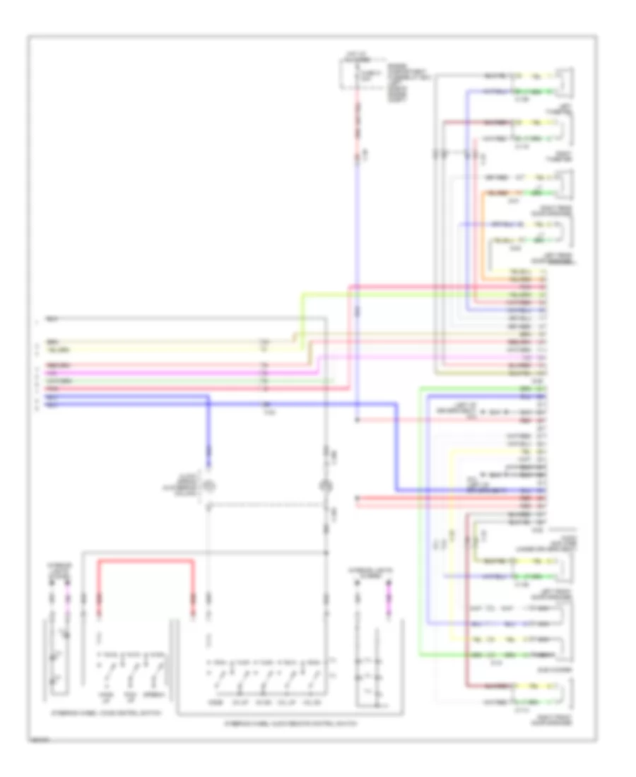
Электросхема магнитолы, Эволюция без Мультисистема связи без Усилитель для Mitsubishi Lancer DE 2011
Электросхема магнитолы, Эволюция без Мультисистема связи без Усилитель для Mitsubishi Lancer DE 2011 - Список элементов:
- (antenna feeder cable)
- (left front engine compt) g17
- Antenna amplifier
- Audio adapter
- Audio switch panel
- C-107
- C-109
- C-116
- C-117
- C-128
- C-129
- C-202
- C-205
- C-23
- C-315
- C-317
- C-32
- C-42
- Can transceiver circuit
- Center panel unit
- Ch dn
- Ch up
- Clock spring (in steering column)
- Combination meter
- Computer data lines system
- Cpu
- D-01
- D-24
- Etacs-ecu (on rear of junction block, behind left end of dash)
- Fuse 16 10a
- Fuse 7 15a
- G4 (behind right kick panel)
- Hang up
- Hot at all times
- Hot w/ acc relay 2 energized
- Ill
- Interface circuit
- Interior lights system
- Lcd panel (audio)
- Left front door speaker
- Left rear door speaker
- Left tweeter
- Mode
- Navigation system
- Nca
- Pick up
- Pnk
- Radio & cd player
- Red
- Right front door speaker
- Right rear door speaker
- Right tweeter
- Roof antenna
- Speech
- Steering wheel audio remote control switch
- Steering wheel voice control switch
- Vol dn
- Vol up
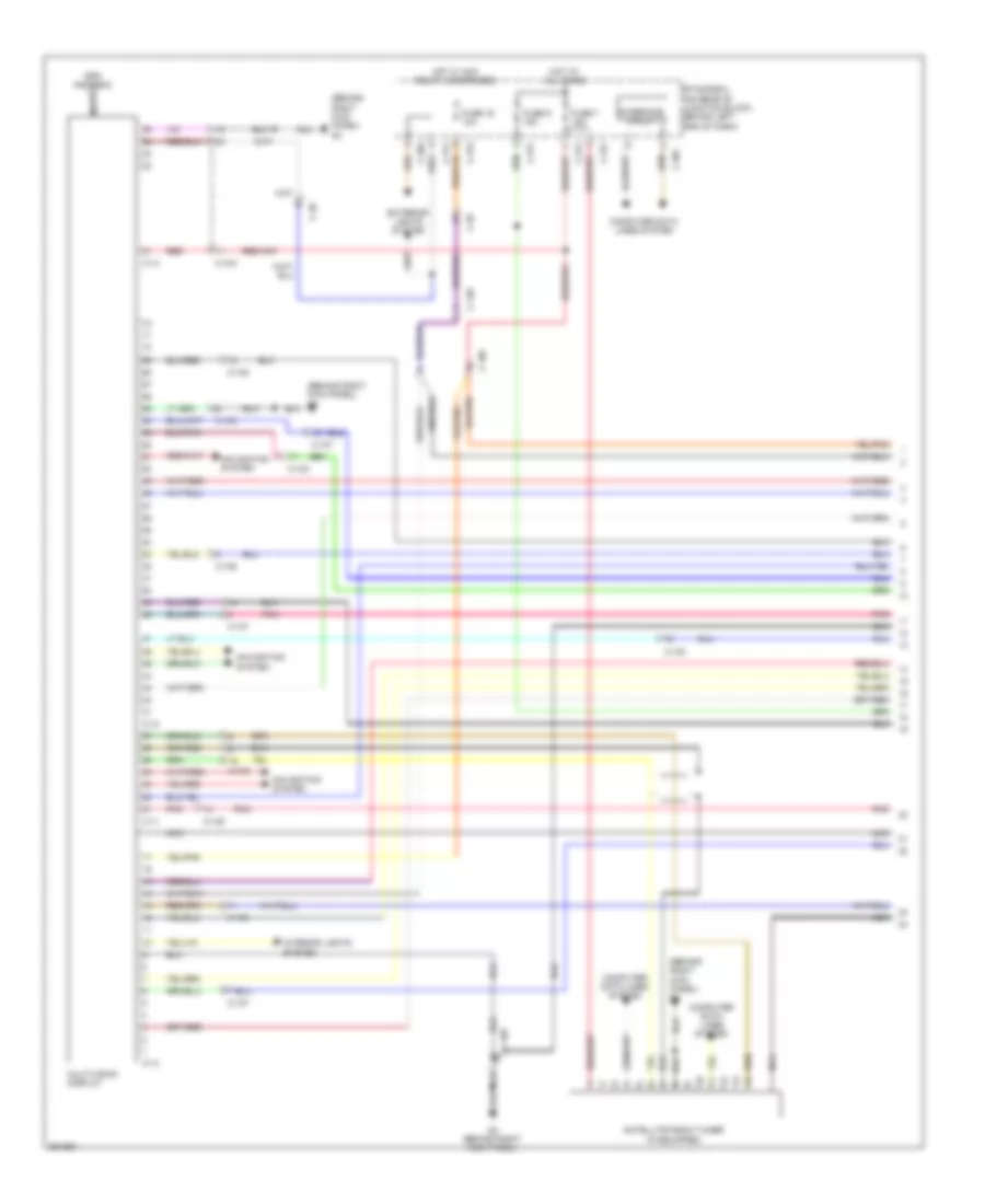
Электросхема магнитолы, Кроме Эволюции С Мультисистема связи С Усилитель (1 из 3) для Mitsubishi Lancer DE 2011
Электросхема магнитолы, Кроме Эволюции С Мультисистема связи С Усилитель (1 из 3) для Mitsubishi Lancer DE 2011 - Список элементов:
- (behind right kick panel) g4
- C-103
- C-105
- C-107
- C-11
- C-12
- C-128
- C-13
- C-14
- C-301
- C-304
- C-311
- C-313
- C-317
- C-36
- C-39
- Computer data lines system
- Etacs-ecu (on rear of junction block, behind left end of dash)
- Exterior lights system
- Fuse 16 10a
- Fuse 7 15a
- Fuse 9 15a
- G4 (behind right kick panel)
- Gps antenna
- Hot at all times
- Hot w/ acc relay 2 energized
- Interface circuit
- Interior lights system
- Multivision display
- Navigation system
- Nca
- Pnk
- Red
- Satellite radio tuner (if equipped)
Электросхема магнитолы, Кроме Эволюции С Мультисистема связи С Усилитель (2 из 3) для Mitsubishi Lancer DE 2011
Электросхема магнитолы, Кроме Эволюции С Мультисистема связи С Усилитель (2 из 3) для Mitsubishi Lancer DE 2011 - Список элементов:
- (antenna feeder cable)
- (turbo: behind center of dash) (except turbo: behind right side of dash) can box unit
- Antenna amplifier
- Audio & video adapter
- C-107
- C-204
- C-205
- Can transceiver circuit
- Ch dn
- Ch up
- Clock spring (in steering column)
- Combination meter
- Computer data lines system
- Cpu
- G14 (behind left kick panel)
- Hang up
- Ill
- Interface circuit
- Interior lights system
- Mode
- Navigation system
- Nca
- Pick up
- Pnk
- Red
- Roof antenna
- Speech
- Steering wheel audio remote control switch
- Steering wheel voice control switch
- Vol dn
- Vol up
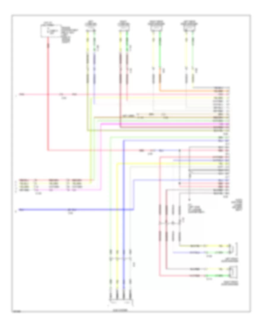
Электросхема магнитолы, Кроме Эволюции С Мультисистема связи С Усилитель (3 из 3) для Mitsubishi Lancer DE 2011
Электросхема магнитолы, Кроме Эволюции С Мультисистема связи С Усилитель (3 из 3) для Mitsubishi Lancer DE 2011 - Список элементов:
- (not used)
- Audio amplifier (under driver's seat)
- C-105
- C-114
- C-115
- C-125
- C-126
- C-22
- C-39
- D-01
- D-15
- D-20
- D-25
- D-26
- Engine compartment relay box (left side of engine compt)
- Fuse 31 30a
- G11 (left side of luggage compartment)
- Hot at all times
- Left front door speaker
- Left rear door speaker
- Left tweeter
- Nca
- Pnk
- Red
- Right front door speaker
- Right rear door speaker
- Right tweeter
- Sub woofer
Электросхема магнитолы, Кроме Эволюции С Мультисистема связи без Усилитель (1 из 3) для Mitsubishi Lancer DE 2011
Электросхема магнитолы, Кроме Эволюции С Мультисистема связи без Усилитель (1 из 3) для Mitsubishi Lancer DE 2011 - Список элементов:
- (behind right kick panel) g4
- C-103
- C-105
- C-107
- C-11
- C-12
- C-128
- C-13
- C-14
- C-301
- C-304
- C-311
- C-313
- C-317
- C-36
- C-39
- Computer data lines system
- Etacs-ecu (on rear of junction block, behind left end of dash)
- Exterior lights system
- Fuse 16 10a
- Fuse 7 15a
- Fuse 9 15a
- G4 (behind right kick panel)
- Gps antenna
- Hot at all times
- Hot w/ acc relay 2 energized
- Interface circuit
- Interior lights system
- Multivision display
- Navigation system
- Nca
- Pnk
- Red
- Satellite radio tuner (if equipped)
Электросхема магнитолы, Кроме Эволюции С Мультисистема связи без Усилитель (2 из 3) для Mitsubishi Lancer DE 2011
Электросхема магнитолы, Кроме Эволюции С Мультисистема связи без Усилитель (2 из 3) для Mitsubishi Lancer DE 2011 - Список элементов:
- (antenna feeder cable)
- (turbo: behind center of dash) (except turbo: behind right side of dash) can box unit
- Antenna amplifier
- C-204
- C-205
- Can transceiver circuit
- Ch dn
- Ch up
- Clock spring (in steering column)
- Combination meter
- Computer data lines system
- Cpu
- G14 (behind left kick panel)
- Hang up
- Ill
- Interface circuit
- Interior lights system
- Mode
- Nca
- Pick up
- Pnk
- Red
- Roof antenna
- Speech
- Steering wheel audio remote control switch
- Steering wheel voice control switch
- Vol dn
- Vol up
Электросхема магнитолы, Кроме Эволюции С Мультисистема связи без Усилитель (3 из 3) для Mitsubishi Lancer DE 2011
Электросхема магнитолы, Кроме Эволюции С Мультисистема связи без Усилитель (3 из 3) для Mitsubishi Lancer DE 2011 - Список элементов:
- Audio & video adapter
- C-105
- C-114
- C-115
- C-125
- C-126
- C-21
- C-36
- D-01
- D-20
- Left front door speaker
- Left rear door speaker
- Left tweeter
- Pnk
- Right front door speaker
- Right rear door speaker
- Right tweeter
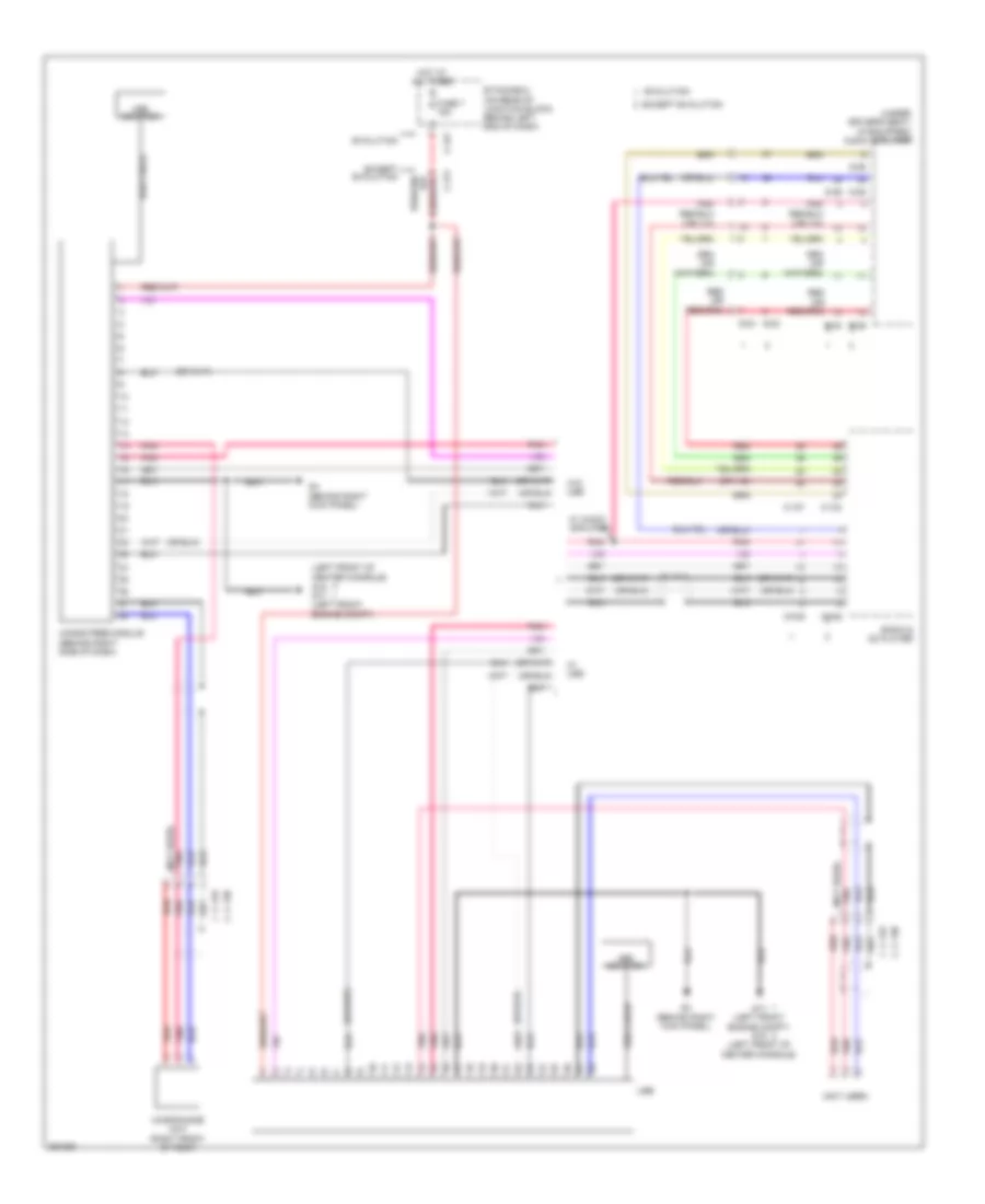
Электросхема магнитолы, Кроме Эволюции без Мультисистема связи С Усилитель (1 из 2) для Mitsubishi Lancer DE 2011
Электросхема магнитолы, Кроме Эволюции без Мультисистема связи С Усилитель (1 из 2) для Mitsubishi Lancer DE 2011 - Список элементов:
- (antenna feeder cable)
- Antenna amplifier
- Audio adapter
- Audio switch panel
- Behind left end of dash)
- C-104
- C-106
- C-128
- C-311
- C-313
- C-317
- C-39
- Can transceiver circuit
- Center panel unit
- Combination meter
- Computer data lines system
- Cpu
- Etacs-ecu (on rear of junction block,
- Fuse 16 10a
- Fuse 7 15a
- G15 (left front of center console)
- G4 (behind right kick panel)
- Hot at all times
- Hot w/ acc relay 2 energized
- Interface circuit
- Interior lights system
- Lcd panel (audio, clock)
- Navigation system
- Nca
- Pnk
- Radio & cd player
- Red
- Roof antenna
- Satellite radio tuner (if equipped)
Электросхема магнитолы, Кроме Эволюции без Мультисистема связи С Усилитель (2 из 2) для Mitsubishi Lancer DE 2011
Электросхема магнитолы, Кроме Эволюции без Мультисистема связи С Усилитель (2 из 2) для Mitsubishi Lancer DE 2011 - Список элементов:
- (left of driver's seat) g12
- Audio amplifier (under driver's seat)
- C-114
- C-115
- C-125
- C-126
- C-204
- C-205
- C-22
- C-39
- Ch dn
- Ch up
- Clock spring (in steering column)
- D-01
- D-15
- D-20
- D-25
- D-26
- Engine compartment fuse/relay box (left side of engine compt)
- Fuse 31 30a
- G12 (left of driver's seat)
- Hang up
- Hot at all times
- Ill
- Interior lights system
- Left front door speaker
- Left rear door speaker
- Left tweeter
- Mode
- Nca
- Pick up
- Pnk
- Red
- Right front door speaker
- Right rear door speaker
- Right tweeter
- Speech
- Steering wheel audio remote control switch
- Steering wheel voice control switch
- Sub woofer
- Vol dn
- Vol up
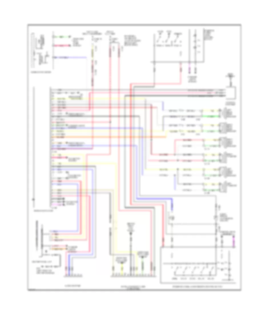
Электросхема магнитолы, Кроме Эволюции без Мультисистема связи без Усилитель для Mitsubishi Lancer DE 2011
Электросхема магнитолы, Кроме Эволюции без Мультисистема связи без Усилитель для Mitsubishi Lancer DE 2011 - Список элементов:
- (antenna feeder cable)
- (behind right kick panel) g4
- Antenna amplifier
- Audio adapter
- Audio switch panel
- C-104
- C-106
- C-114
- C-115
- C-125
- C-126
- C-128
- C-204
- C-205
- C-21
- C-311
- C-313
- C-317
- C-36
- C-39
- Can
- Center panel unit
- Ch dn
- Ch up
- Clock spring (in steering column)
- Combination meter
- Computer data lines system
- Cpu
- D-01
- D-20
- Etacs-ecu (on rear of junction block, behind left end of dash)
- Fuse 16 10a
- Fuse 7 15a
- G15 (left front of center console)
- G4 (behind right kick panel)
- Hang up
- Hot at all times
- Hot w/ acc relay 2 energized
- Ill
- Interface circuit
- Interior lights system
- Lcd panel (audio, clock)
- Left front door speaker
- Left rear door speaker
- Left tweeter
- Mode
- Navigation system
- Nca
- Pick up
- Pnk
- Radio & cd player
- Red
- Right front door speaker
- Right rear door speaker
- Right tweeter
- Roof antenna
- Satellite radio tuner (if equipped)
- Speech
- Steering wheel audio remote control switch
- Steering wheel voice control switch
- Transceiver circuit
- Vol dn
- Vol up
Навигация GPS Парктроники
Электросхема Hands Free Bluetooth подключение телефона, С Мультисистема связи для Mitsubishi Lancer DE 2011
Электросхема Hands Free Bluetooth подключение телефона, С Мультисистема связи для Mitsubishi Lancer DE 2011 - Список элементов:
- (left front of center console) g15 g17 (left front engine compt)
- (not used)
- (under driver's seat) (if equipped) audio amplifier
- C-09
- C-10
- C-105
- C-107
- C-108
- C-11
- C-110
- C-12
- C-13
- C-130
- C-133
- C-14
- C-22
- C-24
- C-311
- C-317
- D-25
- D-26
- D-29
- D-30
- Etacs-ecu (on rear of junction block, behind left end of dash)
- Evolution
- Except evolution
- Fuse 7 15a
- G17 (left front engine compt) g15 (left front of center console)
- G4 (behind right kick panel)
- Hands free module (behind right side of dash)
- Hot at all times
- Microphone unit (right front of roof)
- Multivision display
- Pnk
- Red
- Usb
- Usb adapter
- Usb cable
- W/ audio amplifier
- W/ usb
- W/o usb
Электросхема Hands Free Bluetooth подключение телефона, без Мультисистема связи для Mitsubishi Lancer DE 2011
Электросхема Hands Free Bluetooth подключение телефона, без Мультисистема связи для Mitsubishi Lancer DE 2011 - Список элементов:
- (left front of center console) g15 g17 (left front engine compt)
- (not used)
- (under driver's seat) (if equipped) audio amplifier
- C-104
- C-106
- C-107
- C-109
- C-130
- C-133
- C-22
- C-24
- C-311
- C-317
- D-25
- D-26
- D-29
- D-30
- Etacs-ecu (on rear of junction block, behind left end of dash)
- Evolution
- Except evolution
- Fuse 7 15a
- G17 (left front engine compt) g15 (left front of center console)
- G4 (behind right kick panel)
- Hands free module (behind right side of dash)
- Hot at all times
- Microphone unit (right front of roof)
- Pnk
- Radio & cd player
- Red
- Usb
- Usb adapter
- Usb cable
- W/ audio amplifier
- W/ usb
- W/o usb
Электросхема навигации GPS, эволюция (1 из 3) для Mitsubishi Lancer DE 2011
Электросхема навигации GPS, эволюция (1 из 3) для Mitsubishi Lancer DE 2011 - Список элементов:
- (antenna feeder cable)
- (behind right kick panel) g4
- Antenna amplifier
- C-09
- C-10
- C-106
- C-108
- C-110
- C-12
- C-13
- C-304
- C-311
- C-315
- C-317
- C-42
- C108
- Cable) (gps antenna
- Computer data lines system
- Etacs-ecu (on rear of junction block, behind left end of dash)
- Exterior lights system
- Fuse 16 10a
- Fuse 7 15a
- G4 (behind right kick panel)
- Gps antenna
- Hot at all times
- Hot w/ acc relay 2 energized
- Interior lights system
- J/c c-43
- Multivision display
- Navigation system
- Nca
- Pnk
- Red
- Roof antenna
- Satellite radio tuner
Электросхема навигации GPS, эволюция (2 из 3) для Mitsubishi Lancer DE 2011
Электросхема навигации GPS, эволюция (2 из 3) для Mitsubishi Lancer DE 2011 - Список элементов:
- (turbo: behind center of dash) (except turbo: behind right side of dash) can box unit
- Audio & video adapter
- C-106
- C-108
- C-110
- C-202
- C-205
- C-32
- Can transceiver circuit
- Ch dn
- Ch up
- Circuit interface
- Circuit transceiver can
- Clock spring (in steering column)
- Combination meter
- Computer data lines system
- Cpu
- G4 (behind right kick panel)
- Hang up
- Ill
- Interface circuit
- Interior lights system
- Mode
- Pick up
- Pnk
- Red
- Speech
- Steering wheel audio remote control switch
- Steering wheel voice control switch
- Vol dn
- Vol up
Электросхема навигации GPS, эволюция (3 из 3) для Mitsubishi Lancer DE 2011
Электросхема навигации GPS, эволюция (3 из 3) для Mitsubishi Lancer DE 2011 - Список элементов:
- (left side engine compt) g20
- Audio amplifier (under driver's seat)
- C-110
- C-116
- C-117
- C-128
- C-129
- C-23
- C-24
- C-47
- D-01
- D-16
- D-24
- D-29
- D-30
- Engine compartment relay box (left side of engine compt)
- Fuse 31 30a
- G20 (left side engine compt)
- Hot at all times
- Left front door speaker
- Left rear door speaker
- Left tweeter
- Navigation system
- Nca
- Pnk
- Red
- Right front door speaker
- Right rear door speaker
- Right tweeter
- Sub woofer
Электросхема навигации GPS, Кроме Эволюции С Усилитель (1 из 3) для Mitsubishi Lancer DE 2011
Электросхема навигации GPS, Кроме Эволюции С Усилитель (1 из 3) для Mitsubishi Lancer DE 2011 - Список элементов:
- (behind right kick panel) g4
- C-103
- C-105
- C-107
- C-11
- C-12
- C-128
- C-13
- C-14
- C-301
- C-304
- C-311
- C-313
- C-317
- C-36
- C-39
- Computer data lines system
- Etacs-ecu (on rear of junction block, behind left end of dash)
- Exterior lights system
- Fuse 16 10a
- Fuse 7 15a
- Fuse 9 15a
- G4 (behind right kick panel)
- Gps antenna
- Hot at all times
- Hot w/ acc relay 2 energized
- Interface circuit
- Interior lights system
- Multivision display
- Navigation system
- Nca
- Pnk
- Red
- Satellite radio tuner (if equipped)
Электросхема навигации GPS, Кроме Эволюции С Усилитель (2 из 3) для Mitsubishi Lancer DE 2011
Электросхема навигации GPS, Кроме Эволюции С Усилитель (2 из 3) для Mitsubishi Lancer DE 2011 - Список элементов:
- (antenna feeder cable)
- (turbo: behind center of dash) (except turbo: behind right side of dash) can box unit
- Antenna amplifier
- Audio & video adapter
- C-107
- C-204
- C-205
- Can transceiver circuit
- Ch dn
- Ch up
- Clock spring (in steering column)
- Combination meter
- Computer data lines system
- Cpu
- G14 (behind left kick panel)
- Hang up
- Ill
- Interface circuit
- Interior lights system
- Mode
- Navigation system
- Nca
- Pick up
- Pnk
- Red
- Roof antenna
- Speech
- Steering wheel audio remote control switch
- Steering wheel voice control switch
- Vol dn
- Vol up
Электросхема навигации GPS, Кроме Эволюции С Усилитель (3 из 3) для Mitsubishi Lancer DE 2011
Электросхема навигации GPS, Кроме Эволюции С Усилитель (3 из 3) для Mitsubishi Lancer DE 2011 - Список элементов:
- (not used)
- Audio amplifier (under driver's seat)
- C-105
- C-114
- C-115
- C-125
- C-126
- C-22
- C-39
- D-01
- D-15
- D-20
- D-25
- D-26
- Engine compartment relay box (left side of engine compt)
- Fuse 31 30a
- G11 (left side of luggage compartment)
- Hot at all times
- Left front door speaker
- Left rear door speaker
- Left tweeter
- Nca
- Pnk
- Red
- Right front door speaker
- Right rear door speaker
- Right tweeter
- Sub woofer
Электросхема навигации GPS, Кроме Эволюции без Усилитель (1 из 3) для Mitsubishi Lancer DE 2011
Электросхема навигации GPS, Кроме Эволюции без Усилитель (1 из 3) для Mitsubishi Lancer DE 2011 - Список элементов:
- (behind right kick panel) g4
- C-103
- C-105
- C-107
- C-11
- C-12
- C-128
- C-13
- C-14
- C-301
- C-304
- C-311
- C-313
- C-317
- C-36
- C-39
- Computer data lines system
- Etacs-ecu (on rear of junction block, behind left end of dash)
- Exterior lights system
- Fuse 16 10a
- Fuse 7 15a
- Fuse 9 15a
- G4 (behind right kick panel)
- Gps antenna
- Hot at all times
- Hot w/ acc relay 2 energized
- Interface circuit
- Interior lights system
- Multivision display
- Navigation system
- Nca
- Pnk
- Red
- Satellite radio tuner (if equipped)
Электросхема навигации GPS, Кроме Эволюции без Усилитель (2 из 3) для Mitsubishi Lancer DE 2011
Электросхема навигации GPS, Кроме Эволюции без Усилитель (2 из 3) для Mitsubishi Lancer DE 2011 - Список элементов:
- (antenna feeder cable)
- (turbo: behind center of dash) (except turbo: behind right side of dash) can box unit
- Antenna amplifier
- C-204
- C-205
- Can transceiver circuit
- Ch dn
- Ch up
- Clock spring (in steering column)
- Combination meter
- Computer data lines system
- Cpu
- G14 (behind left kick panel)
- Hang up
- Ill
- Interface circuit
- Interior lights system
- Mode
- Nca
- Pick up
- Pnk
- Red
- Roof antenna
- Speech
- Steering wheel audio remote control switch
- Steering wheel voice control switch
- Vol dn
- Vol up
Электросхема навигации GPS, Кроме Эволюции без Усилитель (3 из 3) для Mitsubishi Lancer DE 2011
Электросхема навигации GPS, Кроме Эволюции без Усилитель (3 из 3) для Mitsubishi Lancer DE 2011 - Список элементов:
- Audio & video adapter
- C-105
- C-114
- C-115
- C-125
- C-126
- C-21
- C-36
- D-01
- D-20
- Left front door speaker
- Left rear door speaker
- Left tweeter
- Pnk
- Right front door speaker
- Right rear door speaker
- Right tweeter
Подогрев стекол и зеркал
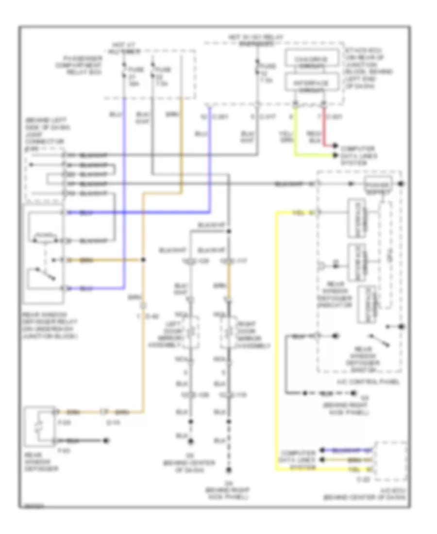
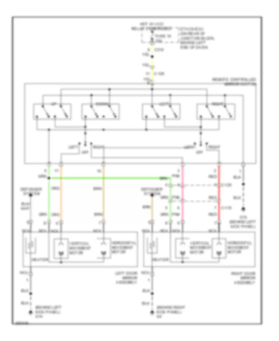
Электросхема подогрева стекол и зеркал, эволюция для Mitsubishi Lancer DE 2011
Электросхема подогрева стекол и зеркал, эволюция для Mitsubishi Lancer DE 2011 - Список элементов:
- (behind left side of dash) joint connector c-03
- A/c control panel
- A/c-ecu (behind center of dash)
- C-116
- C-117
- C-128
- C-129
- C-22
- C-301
- C-317
- Can drive circuit
- Computer data lines system
- Cpu
- D-16
- D-42
- Etacs-ecu (on rear of junction block, behind left end of dash)
- F-03
- F-29
- Fuse 30a
- Fuse 7.5a
- G4 (behind right kick panel)
- G6 (behind center of dash)
- Hot at all times
- Hot w/ ig1 relay energized
- Interface circuit
- Left door mirror assembly
- Nca
- Passenger compartment relay box
- Rear window defogger
- Rear window defogger indicator
- Rear window defogger relay (on underdash junction block)
- Rear window defogger switch
- Right door mirror assembly
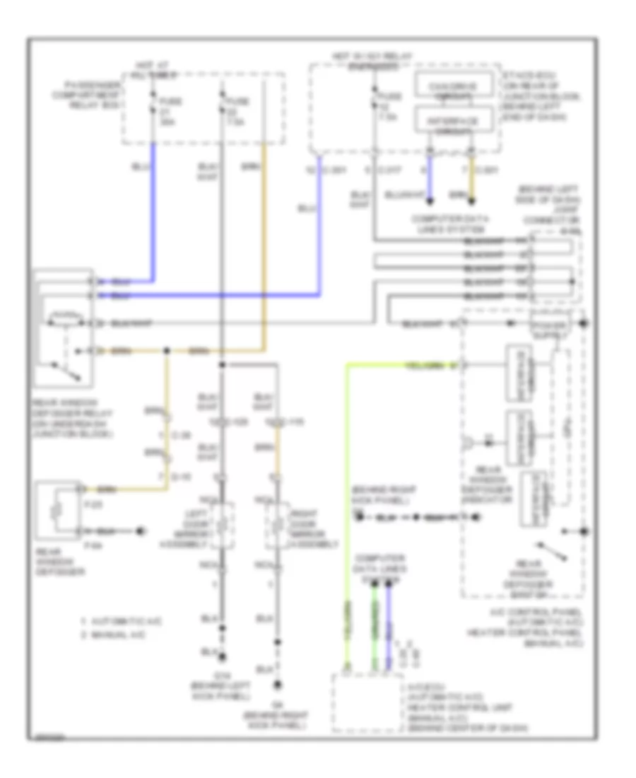
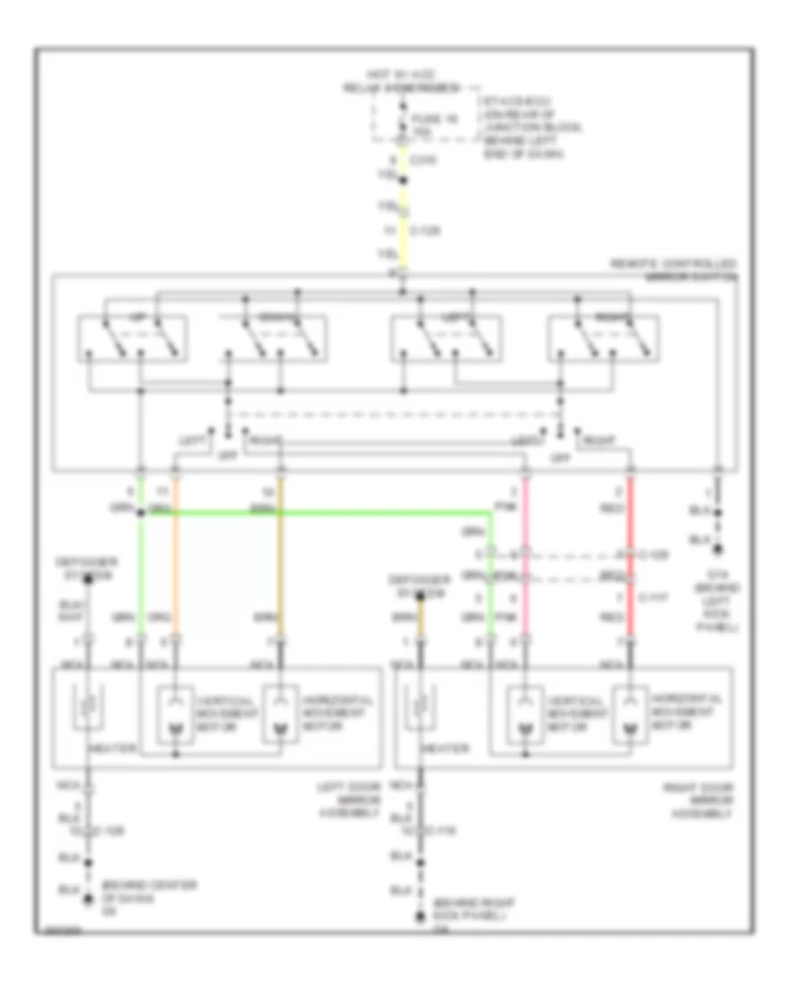
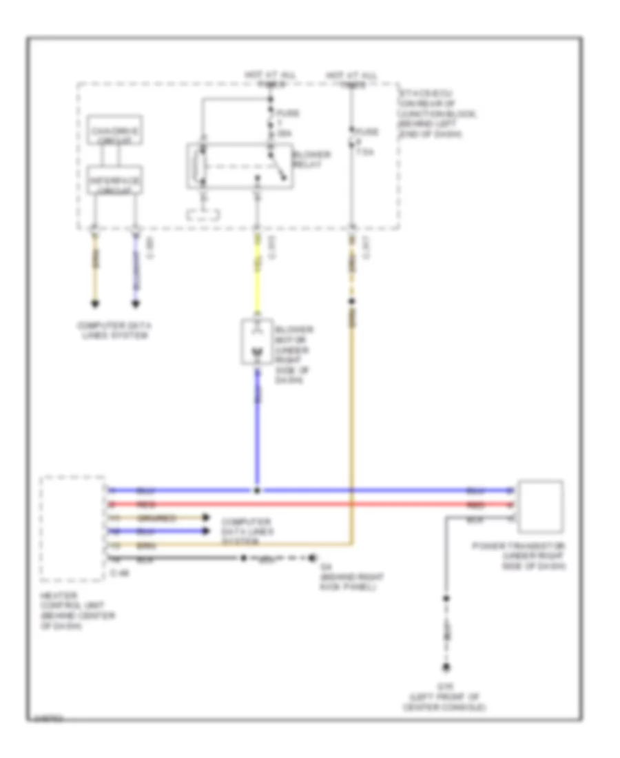
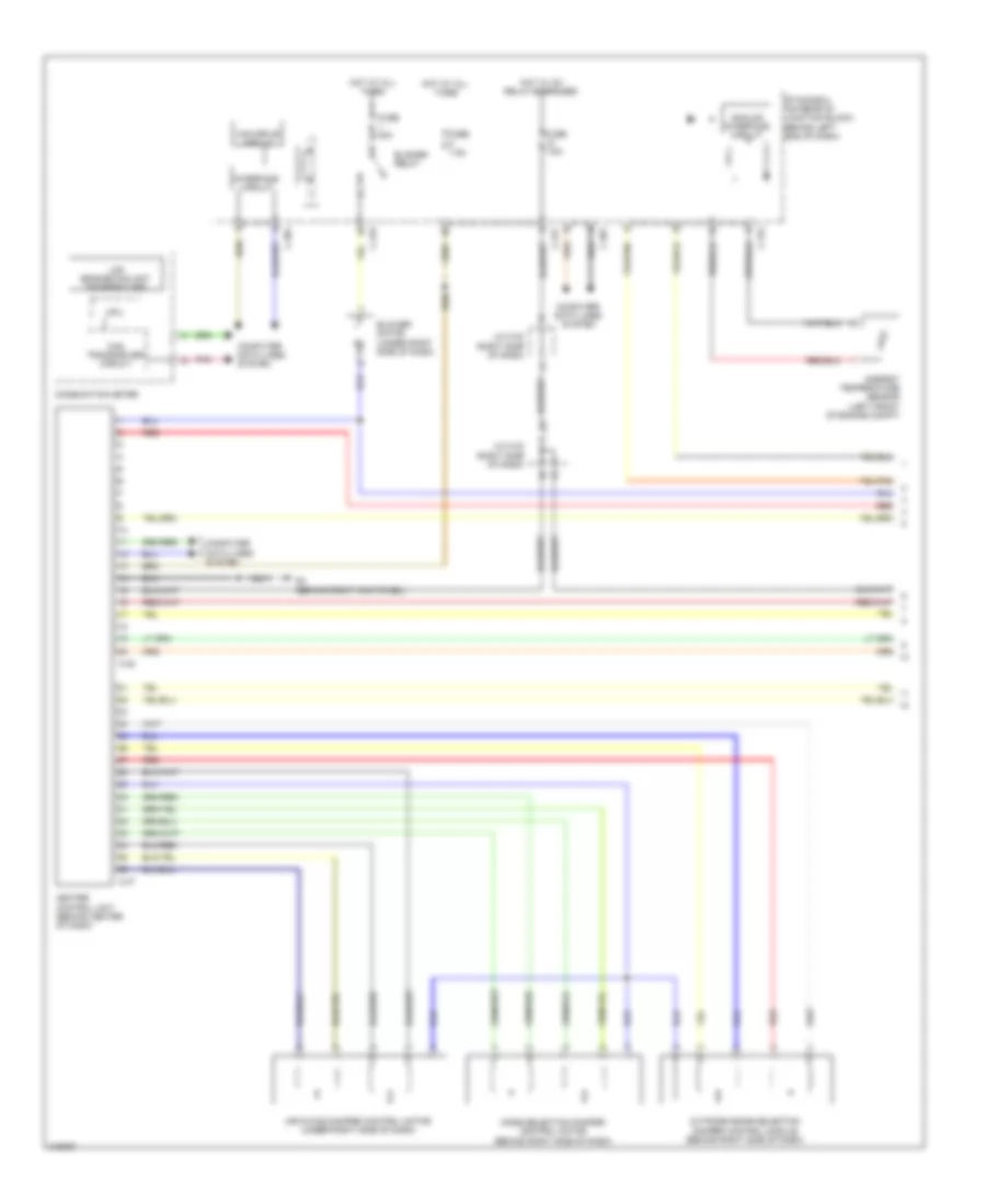
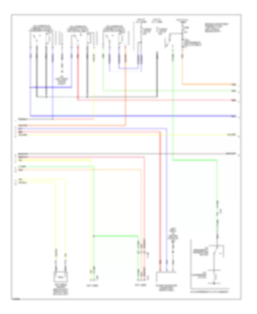
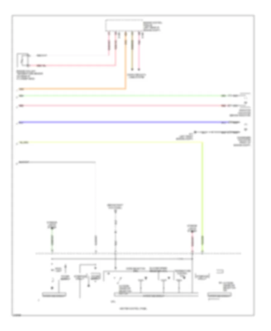
Электросхема подогрева стекол и зеркал, кроме эволюции для Mitsubishi Lancer DE 2011
Электросхема подогрева стекол и зеркал, кроме эволюции для Mitsubishi Lancer DE 2011 - Список элементов:
- (behind left side of dash) joint connector c-03
- (behind right kick panel) g4
- A/c control panel (automatic a/c) heater control panel (manual a/c)
- A/c-ecu (automatic a/c) heater control unit (manual a/c) (behind center of dash)
- Automatic a/c
- C-115
- C-126
- C-20
- C-301
- C-317
- C-36
- C-48
- Can drive circuit
- Computer data lines system
- Cpu
- D-15
- Etacs-ecu (on rear of junction block, behind left end of dash)
- F-04
- F-25
- Fuse 30a
- Fuse 7.5a
- G14 (behind left kick panel)
- G4 (behind right kick panel)
- Hot at all times
- Hot w/ ig1 relay energized
- Interface circuit
- Left door mirror assembly
- Manual a/c
- Nca
- Passenger compartment relay box
- Rear window defogger
- Rear window defogger indicator
- Rear window defogger relay (on underdash junction block)
- Rear window defogger switch
- Right door mirror assembly
ПОДУШКИ БЕЗОПАСНОСТИ AIR BAG
Электросхема подушек безопасности SRS AirBag, эволюция (1 из 4) для Mitsubishi Lancer DE 2011
Электросхема подушек безопасности SRS AirBag, эволюция (1 из 4) для Mitsubishi Lancer DE 2011 - Список элементов:
- Air bag off indicator light (passenger's side)
- C-313
- C-317
- C-36
- Center panel unit
- Connector lock switch (connector coupled: on) (connector uncoupled: off)
- Etacs- ecu (on rear of junction block, behind left end of dash)
- Fuse 7.5a
- Hall ic
- Hot w/ ig1 relay energized
- Interface circuit
- J/c 1 (c-101)
- J/c 4 (c-43) (left kick panel)
- J/c 5 (d-27)
- Left side air bag module squib
- Nca
- Off
- Passenger's seat belt indicator
- Passenger's side seat belt switch (in front passenger's seat belt buckle assembly)
- Red
- Srs ecu (behind lower center of dash)
Электросхема подушек безопасности SRS AirBag, эволюция (2 из 4) для Mitsubishi Lancer DE 2011
Электросхема подушек безопасности SRS AirBag, эволюция (2 из 4) для Mitsubishi Lancer DE 2011 - Список элементов:
- (base of left "b" pillar) left seat belt pre-tensioner
- (base of right "b" pillar) right seat belt pre-tensioner
- (in front passenger's seat back) right side air bag module squib
- Accelero meter
- Connector lock switch (connector coupled: on) (connector uncoupled: off)
- Cpu
- Left curtain air bag module squib (in left "c" pillar)
- Left side impact sensor (base of left "b" pillar)
- Nca
- Off
- Red
- Right curtain air bag module squib (in right "c" pillar)
- Right side impact sensor (base of right "b" pillar)
Электросхема подушек безопасности SRS AirBag, эволюция (3 из 4) для Mitsubishi Lancer DE 2011
Электросхема подушек безопасности SRS AirBag, эволюция (3 из 4) для Mitsubishi Lancer DE 2011 - Список элементов:
- C-301
- C-315
- C-317
- C-41
- Can drive circuit
- Can transceiver circuit
- Combination meter
- Cpu
- D-39-1
- D-39-2
- Data link connector (under left side of dash)
- Driver's seat belt ind
- Driver's side seat belt switch (in driver's seat belt buckle assembly)
- Etacs-ecu (on rear of junction block, behind left end of dash)
- Fuse 10a
- G20 (left side engine compt)
- G4 (behind right kick panel)
- G7 (top left side of headliner)
- Hall ic
- Hot at all times
- Interface circuit
- J/c (can 1) (left top of dash)
- J/c 4
- Lcd (srs)
- Led drive circuit
- Left front weight sensor
- Left rear weight sensor
- Nca
- Occupant classification-ecu
- Pnk
- Red
- Right front seat assembly
- Right front weight sensor
- Right rear weight sensor
- Seat slide sensor (under driver's seat)
- Srs ind
Электросхема подушек безопасности SRS AirBag, эволюция (4 из 4) для Mitsubishi Lancer DE 2011
Электросхема подушек безопасности SRS AirBag, эволюция (4 из 4) для Mitsubishi Lancer DE 2011 - Список элементов:
- (behind right side of dash) front passenger's air bag module squib
- (connector coupled: on) (connector uncoupled: off) connector lock switch
- (connector coupled: on) connector uncoupled: off) connector lock switch
- (in driver's seat) driver's air bag module squib
- (under left side of dash) knee air bag module (squib)
- A-42
- Accelero meter
- C-131
- C-37
- Clock spring (in steering column)
- Connector lock switch (connector coupled: on) (connector uncoupled: off)
- Cpu
- G17 (left front engine compt)
- Left front impact sensor (left front side of engine compt)
- Nca
- Off
- Right front impact sensor (right front side of engine compt)
- Srs ecu (behind lower center of dash)
Электросхема подушек безопасности SRS AirBag, кроме эволюции (1 из 4) для Mitsubishi Lancer DE 2011
Электросхема подушек безопасности SRS AirBag, кроме эволюции (1 из 4) для Mitsubishi Lancer DE 2011 - Список элементов:
- Air bag off indicator light (passenger's side)
- C-30
- C-313
- C-317
- Center panel unit
- Connector lock switch (connector coupled: on) (connector uncoupled: off)
- Etacs- ecu (on rear of junction block, behind left end of dash)
- Fuse 7.5a
- Hall ic
- Hot w/ ig1 relay energized
- Interface circuit
- J/c 1 (c-03) (except turbo: right side of dash) (turbo: behind left side of dash)
- Left side air bag module squib
- Nca
- Off
- Passenger's seat belt indicator
- Passenger's side seat belt switch (in front passenger's seat belt buckle assembly)
- Red
- Srs ecu (behind lower center of dash)
Электросхема подушек безопасности SRS AirBag, кроме эволюции (2 из 4) для Mitsubishi Lancer DE 2011
Электросхема подушек безопасности SRS AirBag, кроме эволюции (2 из 4) для Mitsubishi Lancer DE 2011 - Список элементов:
- (base of left "b" pillar) left seat belt pre-tensioner
- (base of right "b" pillar) right seat belt pre-tensioner
- (in front passenger's seat back) right side air bag module squib
- Accelero meter
- Connector lock switch (connector coupled: on) (connector uncoupled: off)
- Cpu
- Left curtain air bag module squib (in left "c" pillar)
- Left side impact sensor (base of left "b" pillar)
- Nca
- Off
- Red
- Right curtain air bag module squib (in right "c" pillar)
- Right side impact sensor (base of right "b" pillar)
Электросхема подушек безопасности SRS AirBag, кроме эволюции (3 из 4) для Mitsubishi Lancer DE 2011
Электросхема подушек безопасности SRS AirBag, кроме эволюции (3 из 4) для Mitsubishi Lancer DE 2011 - Список элементов:
- C-301
- C-315
- C-317
- C-35
- Can drive circuit
- Can transceiver circuit
- Combination meter
- Cpu
- D-35-1
- D-35-2
- Data link connector (under left side of dash)
- Driver's seat belt ind
- Driver's side seat belt switch (in driver's seat belt buckle assembly)
- Etacs-ecu (on rear of junction block, behind left end of dash)
- Fuse 10a
- G14 (behind left kick panel)
- G6 (behind center of dash)
- Hall ic
- Hot at all times
- Interface circuit
- J/c c-06 (behind left side of dash)
- Lcd (srs)
- Led drive circuit
- Left front weight sensor
- Left rear weight sensor
- Left seat slide sensor (under driver's seat)
- Nca
- Occupant classification-ecu
- Pnk
- Red
- Right front seat assembly
- Right front weight sensor
- Right rear weight sensor
- Srs ind
Электросхема подушек безопасности SRS AirBag, кроме эволюции (4 из 4) для Mitsubishi Lancer DE 2011
Электросхема подушек безопасности SRS AirBag, кроме эволюции (4 из 4) для Mitsubishi Lancer DE 2011 - Список элементов:
- (behind right side of dash) front passenger's air bag module squib
- (connector coupled: on) (connector uncoupled: off) connector lock switch
- (connector coupled: on) connector uncoupled: off) connector lock switch
- (in driver's seat) driver's air bag module squib
- (under left side of dash) knee air bag module (squib)
- A-33
- Accelero meter
- C-122
- C-128
- Clock spring (in steering column)
- Connector lock switch (connector coupled: on) (connector uncoupled: off)
- Cpu
- G4 (behind right kick panel)
- Left front impact sensor (left front side of engine compt)
- Nca
- Off
- Right front impact sensor (right front side of engine compt)
- Srs ecu (behind lower center of dash)
ПРЕДУПРЕЖДАЮЩИЕ СИСТЕМЫ
Электросхема сигнала, эволюция для Mitsubishi Lancer DE 2011
Электросхема сигнала, эволюция для Mitsubishi Lancer DE 2011 - Список элементов:
- (each lcd
- (key reminder)
- Brake ind
- C-23
- C-301
- C-313
- C-315
- C-317
- C-36
- C-37
- C-41
- Can drive circuit
- Center panel unit
- Circuit interface
- Circuit transceiver can
- Column ecu
- Column switch (on top of steering column)
- Combination meter
- Computer data lines system
- Cpu
- Door)
- Drive circuit
- Driver's seat belt ind
- Driver's side seat belt switch (in driver's seat belt buckle assembly)
- Etacs-ecu (on rear of junction block, behind left end of dash)
- Fuse 7.5a
- G18 (left front engine compt)
- G20 (left side engine compt)
- G4 (behind right kick panel)
- Hall ic
- Head
- Hot at all times
- Hot w/ ignition 1 relay energized
- Interface circuit
- Jiont connetor 01 (behind left side odf dash)
- Key reminder switch
- Kos ecu (w/ kos) (left side of dash)
- Lcd
- Led
- Left front door switch (in left "b" pillar)
- Lighting switch
- Nca
- Parking brake switch (under center console)
- Passenger's seat belt ind
- Passenger's seat belt switch (in front passenger's seat belt buckle assembly)
- Pnk
- Push switch
- Srs ecu (behind lower center of dash)
- Tail
- Tone alarm
Электросхема сигнала, кроме эволюции для Mitsubishi Lancer DE 2011
Электросхема сигнала, кроме эволюции для Mitsubishi Lancer DE 2011 - Список элементов:
- (each lcd
- Brake ind
- C-122
- C-21
- C-30
- C-301
- C-313
- C-315
- C-317
- C-35
- Can
- Can drive circuit
- Center panel unit
- Circuit interface
- Circuit transceiver
- Column ecu
- Column switch ecu (on top of steering column)
- Combination meter
- Computer data lines system
- Cpu
- Door)
- Drive circuit
- Driver's seat belt ind
- Driver's side seat belt switch (in driver's seat belt buckle assembly)
- Etacs-ecu (on rear of junction block, behind left end of dash)
- Fuse 7.5a
- G12 (left of driver's seat)
- G15 (left front of center console)
- G4 (behind right kick panel)
- Hall ic
- Head
- Hot at all times
- Hot w/ ig1 relay energized
- Interface circuit
- J/c 01 (behind left side of dash)
- Key reminder switch
- Kos-ecu (w/ kos) (left side of dash)
- Led
- Left front door switch (in left "b" pillar)
- Lighting switch
- Nca
- Parking brake switch (under center console)
- Passenger's seat belt ind
- Passenger's seat belt switch (in front passenger's seat belt buckle assembly)
- Pnk
- Push switch
- Reminder) (key lcd
- Srs-ecu (behind lower center of dash)
- Tail
- Tone alarm
Электросхема системы контроля давления в шинах, эволюция для Mitsubishi Lancer DE 2011
Электросхема системы контроля давления в шинах, эволюция для Mitsubishi Lancer DE 2011 - Список элементов:
- C-301
- C-317
- C-41
- Can drive circuit
- Can transceiver
- Circuit
- Combination meter
- Computer data lines system
- Cpu
- Door locks system
- Etacs-ecu (on rear of junction block, behind left end of dash)
- Fuse 7.5a
- G4 (behind right kick panel)
- G6 (behind center of dash)
- Hot at all times
- Hot w/ ignition 1 relay energized
- Interface circuit
- J/c 01 (behind left side of dash)
- Kos-ecu (w/ kos) (left side of dash)
- Lcd (tire pressure)
- Left front tire pressure sensor
- Left rear tire pressure sensor
- Nca
- Pnk
- Receiver
- Receiver antenna assembly
- Red
- Right front tire pressure sensor
- Right rear tire pressure sensor
- Solid state
- W/ kos
- W/o kos
- Wireless control module (w/o kos) (on ignition switch)
Электросхема системы контроля давления в шинах, кроме эволюции для Mitsubishi Lancer DE 2011
Электросхема системы контроля давления в шинах, кроме эволюции для Mitsubishi Lancer DE 2011 - Список элементов:
- C-317
- Can transceiver
- Circuit
- Combination meter
- Computer data lines system
- Cpu
- Etacs-ecu (on rear of junction block, behind left end of dash)
- Fuse 7.5a
- G4 (behind right kick panel)
- Hot at all times
- Hot w/ ig1 relay energized
- J/c 01 (behind left side of dash)
- Kos
- Lcd (tire pressure)
- Led driver
- Left front tire pressure sensor
- Left rear tire pressure sensor
- Pnk
- Receiver antenna module (w/ kos) (behind center of dash)
- Red
- Right front tire pressure sensor
- Right rear tire pressure sensor
- Solid state
- Tire pressure ind
- W/ kos
- W/o
- W/o kos
- Wireless control module (w/o kos) kos-ecu (w/ kos) (w/ kos: left side of dash) (w/o kos: on ignition switch)
ПРИБОРНАЯ ПАНЕЛЬ
Электросхема панели приборов, эволюция (1 из 2) для Mitsubishi Lancer DE 2011
Электросхема панели приборов, эволюция (1 из 2) для Mitsubishi Lancer DE 2011 - Список элементов:
- Abs ind
- Beam ind
- Brake ind
- C-23
- C-41
- Can transceiver circuit
- Combination meter
- Computer data lines system
- Cpu
- Cruise ind
- Driver's seat belt ind
- Fog ind
- Fuel level sensor
- Fuel level sensor (sub) (top of fuel tank)
- Fuel pump module (top of fuel tank)
- Fuel tank temperature sensor
- G18 (left front engine compt)
- G22
- G4 (behind right kick panel)
- Generator malfunction light ind
- Illum
- Interface circuit
- Interior lights system
- Joint connector (d-27)
- Lcd (abs, asc off, asc operation, tarmac, brake, tarmac, gravel, snow, acd, ayc, asc warning)
- Lcd (each door)
- Lcd (fuel warning, oil)
- Lcd (generator malfunction light)
- Lcd (key reminder)
- Lcd (kos)
- Lcd (odo/trip, fuel gauge, temperature gauge, service reminder, outside temperature)
- Lcd (seat belt)
- Lcd (shift position, normal, sport, s-sport)
- Lcd (srs)
- Lcd (theft alarm indicator)
- Lcd (tire pressure)
- Led drive circuit
- Left turn ind
- Malfunction ind light (service engine soon or check engine lamp)
- Meter information switch
- Parking brake switch (under center console)
- Pnk
- Rheostat
- Right turn ind
- Sound systems
- Speedometer
- Srs ind
- Tachometer
- Tail ind
- Tone alarm
- Warning systems
Электросхема панели приборов, эволюция (2 из 2) для Mitsubishi Lancer DE 2011
Электросхема панели приборов, эволюция (2 из 2) для Mitsubishi Lancer DE 2011 - Список элементов:
- Audio switch panel
- B-09
- B-10
- Brake fluid level switch (on brake fluid reservoir)
- C-301
- C-312
- C-313
- C-317
- C-47
- Can drive circuit
- Center panel unit
- Computer data lines system
- Engine control module (left rear of engine compt)
- Engine oil pressure switch (left front of engine)
- Etacs-ecu (on rear of junction block, behind left end of dash)
- Fuse 12 7.5a
- Fuse 7 15a
- Fuse 8 7.5a
- Fuse 9 15a
- G1 (at right front corner of engine compt)
- G4 (behind right kick panel)
- Hot at all times
- Hot w/ ig1 relay energized
- Interface circuit
- Joint connector c-101
- Lcd panel (audio & clock)
- Left front door switch (in left "b" pillar)
- Left rear door switch (in left "c" pillar)
- Red
- Right front door switch (in right "b" pillar)
- Right rear door switch (in right "c" pillar)
Электросхема панели приборов, кроме эволюции (1 из 2) для Mitsubishi Lancer DE 2011
Электросхема панели приборов, кроме эволюции (1 из 2) для Mitsubishi Lancer DE 2011 - Список элементов:
- Abs ind
- Asc ind
- Asc off ind (except 2.0l turbo w/o color liquid crystal display)
- Beam ind
- Brake ind
- C-21
- C-35
- Can transceiver circuit
- Combination meter
- Computer data lines system
- Cpu
- Cruise ind
- D-08
- Driver's seat belt ind
- Fog ind
- Fuel level sensor
- Fuel level sensor (sub) (top of fuel tank)
- Fuel pump module (top of fuel tank)
- Fuel tank temperature sensor
- G11 (left side of luggage compt)
- G14 (behind left kick panel)
- G4 (behind right kick panel)
- G5 (right of accelerator pedal)
- Generator malfunction light ind
- Illum
- Interface circuit
- Interior lights system
- Lcd (abs, acd(2.0l turbo), asc off, asc operation, asc warning, brake, gravel (2.0l turbo), snow(2.0l turbo, & tarmac(2.0l turbo)
- Lcd (cvt position, cvt temperature & cvt failure)
- Lcd (each door)
- Lcd (engine coolant temperature)
- Lcd (fuel warning & oil pressure)
- Lcd (generator malfunction light)
- Lcd (key reminder)
- Lcd (kos)
- Lcd (odo/trip, fuel gauge, service reminder, information frost, outside temperature & temperature gauge)
- Lcd (shift position, normal sport & s-sport)
- Lcd (theft-alarm ind)
- Lcd (tire pressure)
- Lcd srs
- Led drive circuit
- Left turn ind
- Malfunction ind light (service engine soon or check engine lamp)
- Meter information switch
- Parking brake switch (under center console)
- Pnk
- Rheostat
- Right turn ind
- Sound systems
- Speedometer
- Srs ind
- Tachometer
- Tail ind
- Tire pressure ind
- Tone alarm
- Turbo
- Warning systems
Электросхема панели приборов, кроме эволюции (2 из 2) для Mitsubishi Lancer DE 2011
Электросхема панели приборов, кроме эволюции (2 из 2) для Mitsubishi Lancer DE 2011 - Список элементов:
- Audio switch panel
- B-108
- B-109
- B-16
- Brake fluid level switch (on brake fluid reservoir)
- C-301
- C-311
- C-313
- C-39
- C312
- Can drive circuit
- Center panel unit
- Computer data lines system
- Engine control module (left rear of engine compt)
- Engine oil pressure switch (left front of engine)
- Etacs-ecu (on rear of junction block, behind left end of dash)
- Except 2.0l turbo
- Fuse 12 7.5a
- Fuse 7 15a
- Fuse 8 7.5a
- Fuse 9 15a
- G1 (at right front corner of engine compt)
- G4 (behind right kick panel)
- Hot at all times
- Hot w/ ig1 relay energized
- Interface circuit
- Joint connector c-03 (right side of dash)
- Lcd panel (audio & clock)
- Left front door switch (in left "b" pillar)
- Left rear door switch (in left "c" pillar)
- Pnk
- Red
- Right front door switch (in right "b" pillar)
- Right rear door switch (in right "c" pillar)
ПРИВОД ЗЕРКАЛ
Электросхема привода зеркал, эволюция для Mitsubishi Lancer DE 2011
Электросхема привода зеркал, эволюция для Mitsubishi Lancer DE 2011 - Список элементов:
- (behind center of dash) g6
- (behind right kick panel) g4
- C-117
- C-129
- C315
- Defogger system
- Down
- Etacs-ecu (on rear of junction block, behind left end of dash)
- Fuse 16 10a
- G14 (behind left kick panel)
- Heater
- Horizontal movement motor
- Hot w/ acc relay 2 energized
- Left
- Left door mirror assembly
- Nca
- Off
- Pnk
- Red
- Remote controlled mirror switch
- Right
- Right door mirror assembly
- Vertical movement motor
Электросхема привода зеркал, кроме эволюции для Mitsubishi Lancer DE 2011
Электросхема привода зеркал, кроме эволюции для Mitsubishi Lancer DE 2011 - Список элементов:
- (behind left kick panel) g14
- (behind right kick panel) g4
- C-115
- C-126
- Defogger system
- Down
- Etacs-ecu (on rear of junction block, behind left end of dash)
- Fuse 16 10a
- G14 (behind left kick panel)
- Heater
- Horizontal movement motor
- Hot w/ acc relay 2 energized
- Left
- Left door mirror assembly
- Nca
- Off
- Pnk
- Red
- Remote controlled mirror switch
- Right
- Right door mirror assembly
- Vertical movement motor
ПРИВОД ЛЮКА И КРЫШИ
Электросхема привода люка или крыши для Mitsubishi Lancer DE 2011
Электросхема привода люка или крыши для Mitsubishi Lancer DE 2011 - Список элементов:
- (top left side of headliner)
- C-130
- C-133
- C-316
- C-317
- Close/ down
- Cpu
- Drive circuit
- Etacs-ecu (on rear of junction block, behind left end of dash)
- Evolution
- Except
- Fuse 20a
- Fuse 7.5a
- Hall sensor
- Hot at all times
- Hot w/ ig1 relay energized
- Input circuit
- Interface circuit
- Joint connector c-101 joint connector c-03 (except evolution: right side of dash)
- Lin drive circuit
- Off
- Open
- Sunroof ecu (in center headliner)
- Sunroof motor
- Sunroof switch
ПРИВОД СТЕКЛОПОДЪЕМНИКОВ
Электросхема стеклоподъемников, эволюция для Mitsubishi Lancer DE 2011
Электросхема стеклоподъемников, эволюция для Mitsubishi Lancer DE 2011 - Список элементов:
- (in left "b" pillar) left front door switch
- (left front engine compt) g18
- Auto down
- Auto up
- C116
- C128
- C129
- C23
- C301
- C311
- C313
- C315
- C317
- C42
- Can drive circuit
- Circuit interface
- Circuit lin drive
- Computer data lines system
- Connector (under left side of dash)
- Cpu
- D01
- D24
- Data link
- Down
- E-09
- Etacs-ecu (on rear of junction block, behind left end of dash)
- Front power window sub switch
- Fuse 10a
- Fuse 30a
- Fuse 7.5a
- G18 (left front engine compt)
- Hot at all times
- Ill
- Interface circuit
- Joint connector d-27
- Left front power window motor (center of driver's door)
- Left front power window switch
- Left rear power window motor (center of left rear door)
- Left rear power window sub switch
- Left rear power window switch
- Lock
- Off
- Pnk
- Power window lock switch
- Power window main switch
- Power window relay
- Red
- Right front power window motor (center of front passenger's door)
- Right front power window switch
- Right rear power window motor (center of right rear door)
- Right rear power window sub switch
- Right rear power window switch
- Unlock
Электросхема стеклоподъемников, кроме эволюции для Mitsubishi Lancer DE 2011
Электросхема стеклоподъемников, кроме эволюции для Mitsubishi Lancer DE 2011 - Список элементов:
- (in left "b" pillar) left front door switch
- Auto down
- Auto up
- C114
- C125
- C126
- C21
- C301
- C311
- C313
- C315
- C317
- C36
- Can drive circuit
- Circuit interface
- Circuit lin drive
- Computer data lines system
- Connector (under left side of dash)
- Cpu
- D01
- D20
- Data link
- Door locks system
- Down
- E-09
- Etacs-ecu (on rear of junction block, behind left end of dash)
- Front power window sub switch
- Fuse 10a
- Fuse 30a
- Fuse 7.5a
- G14 (behind left kick panel)
- Hot at all times
- Ill
- Interface circuit
- Left front power window motor (center of driver's door)
- Left front power window switch
- Left rear power window motor (center of left rear door)
- Left rear power window sub switch
- Left rear power window switch
- Lin drive circuit
- Lock
- Lock switch
- Off
- Power window main switch
- Power window relay
- Red
- Right front power window motor (center of front passenger's door)
- Right front power window switch
- Right rear power window motor (center of right rear door)
- Right rear power window sub switch
- Right rear power window switch
- Unlock
Противоугонная система Сигнализация
Электросхема открывания авто, эволюция (1 из 2) для Mitsubishi Lancer DE 2011
Электросхема открывания авто, эволюция (1 из 2) для Mitsubishi Lancer DE 2011 - Список элементов:
- (behind center of dash) g6
- C-301
- C-304
- C-312
- C-313
- C-316
- C-317
- C-41
- Can drive circuit
- Center panel unit
- Circuit interface
- Circuit lin drive
- Computer data lines system
- D-16
- Door locks system
- Ector 1
- Etacs-ecu (on rear of junction block, behind left end of dash)
- F-27
- Fuse 15a
- Fuse 7.5a
- G11 (left side of luggage compt)
- G4 (behind right kick panel)
- G6 (behind center of dash)
- Headlights system
- Hot at all times
- Hot w/ ig1 relay energized
- Immobilizer antenna
- Joint conn-
- Joint connector (can 1) (left top of dash)
- Kos-ecu (w/ keyless entry) (left side of dash)
- Pnk
- Receiver
- Receiver antenna assembly
- Red
- Theft-alarm indicator
- Trunk lid latch
- W/ keyless entry
- W/o keyless entry
- Wireless control module (w/o keyless entry) (on ignition switch)
Электросхема открывания авто, эволюция (2 из 2) для Mitsubishi Lancer DE 2011
Электросхема открывания авто, эволюция (2 из 2) для Mitsubishi Lancer DE 2011 - Список элементов:
- (right rear of engine compt) (w/o theft- alarm sensor) theft-alarm horn
- A-04
- A-60
- C-130
- Can transceiver circuit
- Combination meter
- Cpu
- D-45
- Engine compartment relay box
- Exterior lights & headlights systems
- Fuse 4 10a
- Fuse 9 20a
- G19 (left side of engine compt)
- G5 (right of accelerator pedal)
- Hood switch
- Horn relay
- Horns system
- Hot at all times
- Lcd (theft alarm indicator)
- Left front door switch (in left "b" pillar)
- Left rear door switch (in left "c" pillar)
- Lin cut off control unit (w/theft alarm sensor) (left end of dash)
- Nca
- Pnk
- Red
- Right front door switch (in right "b" pillar)
- Right rear door switch (in right "c" pillar)
- Theft- alarm sensor (w/theft alarm sensor) (front center of roof)
- Theft- alarm siren (w/ theft- alarm sensor) (right rear of engine compt)
- Theft-alarm horn relay (w/o theft- alarm sensor) (on underhood fuse/relay block)
- Tone alarm
Электросхема открывания авто, кроме эволюции (1 из 2) для Mitsubishi Lancer DE 2011
Электросхема открывания авто, кроме эволюции (1 из 2) для Mitsubishi Lancer DE 2011 - Список элементов:
- (behind left kick panel) g14
- C-301
- C-304
- C-312
- C-313
- C-316
- C-317
- Can drive circuit
- D-15
- Etacs-ecu (on rear of junction block, behind left end of dash)
- F-23
- F-30
- Fuse 15a
- Fuse 7.5a
- G10 (at left "c" pillar)
- G4 (behind right kick panel)
- Hatchback
- Headlights system
- Headlights, exterior lights & systems
- Horns system
- Hot at all times
- Hot w/ ig1 relay energized
- Interface circuit
- Joint connector (can 1)
- Joint connector 1
- Keyless entry receiver
- Kos-ecu (w/ keyless entry) (left side of dash)
- Liftgate switch
- Lin drive circuit
- Nca
- Receiver antenna module (behind center of dash)
- Receiver keyless entry
- Red
- Sedan
- Trunk lid lock actuator (center rear of trunk lid)
- Wireless control module (w/o keyless entry) (on ignition switch)
Электросхема открывания авто, кроме эволюции (2 из 2) для Mitsubishi Lancer DE 2011
Электросхема открывания авто, кроме эволюции (2 из 2) для Mitsubishi Lancer DE 2011 - Список элементов:
- A-63
- C-127
- Can transceiver circuit
- Center panel unit
- Combination meter
- Computer data lines system
- Cp4
- D-47
- G1 (at right front corner of engine compt)
- G16 (rear of engine compt)
- G7 (top left side of headliner)
- Hood latch switch (on hood latch)
- Lcd (theft-alarm indicator)
- Left front door switch (in left "b" pillar)
- Left rear door switch (in left "c" pillar)
- Lin cut off control unit (w/theft alarm sensor) (left end of dash)
- Nca
- Pnk
- Red
- Right front door switch (in right "b" pillar)
- Right rear door switch (in right "c" pillar)
- Theft- alarm sensor (if equipped) (front center of roof)
- Theft- alarm siren (w/ theft alarm sensor) (right rear of engine compt)
- Theft-alarm indicator
- Tone alarm
Электросхема иммобилайзера, эволюция для Mitsubishi Lancer DE 2011
Электросхема иммобилайзера, эволюция для Mitsubishi Lancer DE 2011 - Список элементов:
- B-10
- C-307
- C-317
- Computer data lines system
- Door locks system
- Engine compartment relay box
- Engine control module (left rear of engine compt)
- Engine controls system
- Etacs-ecu (on rear of junction block, behind left end of dash)
- Fuse 10a
- Fuse 30a
- Fuse 7.5a
- G4 (behind right kick panel)
- G6 (behind center of dash)
- Hot at all times
- Hot w/ ig1 relay energized
- Id code (transponder)
- Immobilizer antenna
- Joint connector-c101
- Kos-ecu (w/ keyless entry) (left side of dash)
- Mfi relay
- Receiver antenna module (on ignition switch)
- Red
- Wireless control module (w/o keyless entry) (on ignition switch)
Электросхема иммобилайзера, кроме эволюции для Mitsubishi Lancer DE 2011
Электросхема иммобилайзера, кроме эволюции для Mitsubishi Lancer DE 2011 - Список элементов:
- B-109
- C-307
- C-317
- Computer data lines system
- Engine compartment relay box
- Engine control module (left rear of engine compt)
- Engine controls system
- Etacs-ecu (on rear of junction block, behind left end of dash)
- Fuse 10a
- Fuse 30a
- Fuse 7.5a
- G4 (behind right kick panel)
- Hot at all times
- Hot w/ ig1 relay energized
- Id code (transponder)
- Immobilizer antenna
- Joint connector 1
- Kos-ecu (w/ keyless entry) (left side of dash)
- Mfi relay
- Receiver antenna module (on ignition switch)
- Red
- Wireless control module (w/o keyless entry) (on ignition switch)
СИСТЕМА АНТИБЛОКИРОВОЧНОЙ ТОРМОЗНОЙ СИСТЕМЫ ABS
2.0L
2.0L, Электросхема антиблокировочной тормозной системы АБС (ABS), С Активное Управление Блоком (1 из 2) для Mitsubishi Lancer DE 2011
2.0L, Электросхема антиблокировочной тормозной системы АБС (ABS), С Активное Управление Блоком (1 из 2) для Mitsubishi Lancer DE 2011 - Список элементов:
- Asc-ecu (right rear of engine compt)
- C-39
- Computer data lines system
- D-11
- D-15
- Engine compartment fuse/relay box (left side of engine compt)
- Fusible link 26 40a
- Fusible link 27 30a
- G & yaw rate sensor (lower center of dash)
- G13 (behind left side of dash)
- Hot at all times
- Hydraulic unit
- Left front wheel speed sensor (on left front wheel hub assembly)
- Left rear wheel speed sensor (at left rear wheel hub assembly)
- Motor m
- Nca
- Pnk
- Pressure sensor
- Right front wheel speed sensor (on right front wheel hub assembly)
- Right rear wheel speed sensor (at right rear wheel hub assembly)
- Solenoid valve
2.0L, Электросхема антиблокировочной тормозной системы АБС (ABS), С Активное Управление Блоком (2 из 2) для Mitsubishi Lancer DE 2011
2.0L, Электросхема антиблокировочной тормозной системы АБС (ABS), С Активное Управление Блоком (2 из 2) для Mitsubishi Lancer DE 2011 - Список элементов:
- (at right front corner of engine compt)
- (not used)
- (right of accelerator pedal) g5
- Abs ind
- Asc ind
- Asc off ind (w/o colour liquid crystal display)
- Asc off switch
- Brake fluid level switch (on brake fluid reservoir)
- Brake ind
- C-128
- C-21
- C-301
- C-304
- C-311
- C-312
- C-313
- C-315
- C-317
- C-36
- C-51
- Can transceiver circuit
- Combination meter
- Computer data lines system
- Cpu
- Etacs-ecu (on rear of junction block, behind left end of dash)
- Fuse 10a
- Fuse 2 15a
- Fuse 7.5a
- Fuse 8 7.5a
- Fuse 9 15a
- G5 (right of accelerator pedal)
- Hot at all times
- Hot w/ ig1 relay energized
- Illum
- Interface circuit
- Interior lights system
- J/c 1
- Lcd (asc off) (asc operation) (asc warning) (brake) (abs)
- Led drive circuit
- Nca
- Parking brake switch (under center console)
- Pnk
- Red
- Steering wheel sensor (in steering wheel)
- Stoplight switch (under left side of dash)
2.0L, Электросхема антиблокировочной тормозной системы АБС (ABS), без Активное Управление Блоком для Mitsubishi Lancer DE 2011
2.0L, Электросхема антиблокировочной тормозной системы АБС (ABS), без Активное Управление Блоком для Mitsubishi Lancer DE 2011 - Список элементов:
- (at right front corner of engine compt) g1
- (behind left side of dash) g13
- (right of accelerator pedal) g5
- Abs ind
- Analog interface circuit
- Asc-ecu (right rear of engine compt)
- Brake fluid level switch (on brake fluid reservoir)
- Brake ind
- C-21
- C-301
- C-304
- C-312
- C-317
- C-39
- Can drive circuit
- Can transceiver circuit
- Combination meter
- Computer data lines system
- Cpu
- D-11
- D-15
- Engine compartment fuse/relay box (left side of engine compt)
- Etacs-ecu (on rear of junction block, behind left end of dash)
- Fuse 12 7.5a
- Fuse 2 15a
- Fusible link 26 40a
- Fusible link 27 30a
- Hot at all times
- Hot w/ ig1 relay energized
- Hydraulic unit
- Interface circuit
- Lcd (abs brake)
- Led drive circuit
- Left front wheel speed sensor (on left front wheel hub assembly)
- Left rear wheel speed sensor (at left rear wheel hub assembly)
- Motor
- Nca
- Parking brake switch (under center console)
- Pnk
- Red
- Right front wheel speed sensor (on right front wheel hub assembly)
- Right rear wheel speed sensor (at right rear wheel hub assembly)
- Solenoid valve
- Stoplight switch (under left side of dash)
2.0L ТУРБО
2.0L турбо, Электросхема антиблокировочной тормозной системы АБС (ABS), эволюция (1 из 2) для Mitsubishi Lancer DE 2011
2.0L турбо, Электросхема антиблокировочной тормозной системы АБС (ABS), эволюция (1 из 2) для Mitsubishi Lancer DE 2011 - Список элементов:
- (left side of engine compt) g19
- Asc-ecu (right rear of engine compt)
- C-130
- C-21
- C-45
- C-47
- Computer data lines system
- D-12
- Electric pump (right rear corner of vehicle)
- Electric pump relay (on underhood fuse/relay block)
- Engine compartment fuse/relay box (left side of engine compt)
- Fusible link 26 40a
- Fusible link 27 30a
- Fusible link 35 80a
- Fusible link box (next to battery)
- G & yaw rate sensor (lower center of dash)
- G12 (left of drivers seat)
- G19 (left side of engine compt)
- G9 (at right "c" pillar)
- Hot at all times
- Hydraulic unit
- Left front wheel speed sensor (on left front wheel hub assembly)
- Left rear wheel speed sensor (at left rear wheel hub assembly)
- Motor m
- Nca
- Pnk
- Pressure sensor
- Red
- Right front wheel speed sensor (on right front wheel hub assembly)
- Right rear wheel speed sensor (at right rear wheel hub assembly)
- Solenoid valve
2.0L турбо, Электросхема антиблокировочной тормозной системы АБС (ABS), эволюция (2 из 2) для Mitsubishi Lancer DE 2011
2.0L турбо, Электросхема антиблокировочной тормозной системы АБС (ABS), эволюция (2 из 2) для Mitsubishi Lancer DE 2011 - Список элементов:
- (at right "c" pillar) g9
- (in steering wheel) steering wheel sensor
- (left front engine compt) g18
- (left of drivers seat) g12
- (on brake fluid reservoir) brake fluid level switch
- (under right rear of luggage compt) pressure sensor
- (w/ steering wheel audio remote control switch) awc switch
- Abs ind
- Asc off switch
- Awc switch (w/o steering wheel audio remote control switch)
- Awc-ecu (left side of dash)
- Brake ind
- C-202
- C-205
- C-23
- C-301
- C-304
- C-31
- C-311
- C-312
- C-313
- C-315
- C-317
- C-41
- C-42
- C-47
- Can transceiver circuit
- Clock spring (in steering column)
- Combination meter
- Computer data lines system
- Cpu
- D-11
- Etacs-ecu (on rear of junction block, behind left end of dash)
- F-11
- Fuse 10a
- Fuse 2 15a
- Fuse 7.5a
- Fuse 8 7.5a
- Fuse 9 15a
- G20 (left side engine compt)
- G6 (behind center of dash)
- Hot at all times
- Hot w/ ig1 relay energized
- Ill
- Illum
- Interface circuit
- Interior lights system
- J/c 1
- J/c 4
- J/c 5
- Lcd (abs) (acd) (asc off) (asc operation) (asc warning) (brake) (gravel) (ayc) (snow) (tarmac)
- Led drive circuit
- Left direction valve (right rear of trunk)
- Mode (+)
- Mode (-)
- Nca
- Parking brake switch (under center console)
- Pnk
- Prop- ortioning valve (acd control) (right rear corner of vehicle)
- Prop- ortioning valve (ayc control) (right rear corner of vehicle)
- Red
- Right direction valve (right rear of trunk)
- Stoplight switch (under left side of dash)
- Used) c-206
2.0L Турбо, Электросхема антиблокировочной тормозной системы АБС (ABS), Кроме Эволюции С Активное Управление Блоком (1 из 2) для Mitsubishi Lancer DE 2011
2.0L Турбо, Электросхема антиблокировочной тормозной системы АБС (ABS), Кроме Эволюции С Активное Управление Блоком (1 из 2) для Mitsubishi Lancer DE 2011 - Список элементов:
- Asc-ecu (right rear of engine compt)
- C-128
- C-39
- C-46
- Computer data lines system
- D-11
- D-15
- D-41
- Electric pump
- Electric pump relay (on underhood fuse/relay block)
- Engine compartment fuse/relay box (left side of engine compt)
- Fusible link 26 40a
- Fusible link 27 30a
- Fusible link 35 80a
- Fusible link box (next to battery)
- G & yaw rate sensor (lower center of dash)
- G13 (behind left side of dash)
- G18 (left front engine compt)
- G9 (at right "c" pillar)
- Hot at all times
- Hydraulic unit
- Left front wheel speed sensor (on left front wheel hub assembly)
- Left rear wheel speed sensor (at left rear wheel hub assembly)
- Motor m
- Nca
- Pnk
- Pressure sensor
- Red
- Right front wheel speed sensor (on right front wheel hub assembly)
- Right rear wheel speed sensor (at right rear wheel hub assembly)
- Solenoid valve
2.0L Турбо, Электросхема антиблокировочной тормозной системы АБС (ABS), Кроме Эволюции С Активное Управление Блоком (2 из 2) для Mitsubishi Lancer DE 2011
2.0L Турбо, Электросхема антиблокировочной тормозной системы АБС (ABS), Кроме Эволюции С Активное Управление Блоком (2 из 2) для Mitsubishi Lancer DE 2011 - Список элементов:
- (abs)
- (acd)
- (asc off) (asc operation)
- (asc warning)
- (at right front corner of engine compt) g1
- (behind left kick panel) g14
- (brake)
- (gravel)
- (on brake fluid reservoir) brake fluid level switch
- (snow)
- (tarmac)
- Abs ind
- Asc ind
- Asc off switch
- Awc switch
- Awc-ecu (left side of dash)
- Brake ind
- C-21
- C-301
- C-304
- C-311
- C-312
- C-313
- C-315
- C-317
- C-36
- Circuit interface
- Circuit transceiver can
- Combination meter
- Computer data lines system
- Cpu
- D-11
- Etacs-ecu (on rear of junction block, behind left end of dash)
- Fuse 10a
- Fuse 2 15a
- Fuse 7.5a
- Fuse 8 7.5a
- Fuse 9 15a
- G12 (left of drivers seat)
- G5 (right of accelerator pedal)
- G9 (at right "c" pillar)
- Hot at all times
- Hot w/ ig1 relay energized
- Illum
- Interior lights system
- J/c 1
- J/c 3
- Lcd
- Led drive circuit
- Nca
- Parking brake switch (under center console)
- Pnk
- Pressure sensor (under right rear of luggage compt)
- Proportioning valve (acd control) (right rear corner of vehicle)
- Red
- Rheostat
- Steering wheel sensor (in steering wheel)
- Stoplight switch (under left side of dash)
2.0L турбо, Электросхема антиблокировочной тормозной системы АБС (ABS), кроме эволюции без активное управление блоком для Mitsubishi Lancer DE 2011
2.0L турбо, Электросхема антиблокировочной тормозной системы АБС (ABS), кроме эволюции без активное управление блоком для Mitsubishi Lancer DE 2011 - Список элементов:
- (at right front corner of engine compt) g1
- (behind left side of dash) g13
- (right of accelerator pedal) g5
- Abs ind
- Analog interface circuit
- Asc-ecu (right rear of engine compt)
- Brake fluid level switch (on brake fluid reservoir)
- Brake ind
- C-21
- C-301
- C-304
- C-312
- C-317
- C-39
- Can drive circuit
- Can transceiver circuit
- Combination meter
- Computer data lines system
- Cpu
- D-11
- D-15
- Engine compartment fuse/relay box (left side of engine compt)
- Etacs-ecu (on rear of junction block, behind left end of dash)
- Fuse 12 7.5a
- Fuse 2 15a
- Fusible link 26 40a
- Fusible link 27 30a
- Hot at all times
- Hot w/ ig1 relay energized
- Hydraulic unit
- Interface circuit
- Lcd (abs brake)
- Led drive circuit
- Left front wheel speed sensor (on left front wheel hub assembly)
- Left rear wheel speed sensor (at left rear wheel hub assembly)
- Motor
- Nca
- Parking brake switch (under center console)
- Pnk
- Red
- Right front wheel speed sensor (on right front wheel hub assembly)
- Right rear wheel speed sensor (at right rear wheel hub assembly)
- Solenoid valve
- Stoplight switch (under left side of dash)
2.4L
2.4L, Электросхема антиблокировочной тормозной системы АБС (ABS), С Активное Управление Блоком (1 из 2) для Mitsubishi Lancer DE 2011
2.4L, Электросхема антиблокировочной тормозной системы АБС (ABS), С Активное Управление Блоком (1 из 2) для Mitsubishi Lancer DE 2011 - Список элементов:
- Asc-ecu (right rear of engine compt)
- C-39
- Computer data lines system
- D-11
- D-15
- Engine compartment fuse/relay box (left side of engine compt)
- Fusible link 26 40a
- Fusible link 27 30a
- G & yaw rate sensor (lower center of dash)
- G13 (behind left side of dash)
- Hot at all times
- Hydraulic unit
- Left front wheel speed sensor (on left front wheel hub assembly)
- Left rear wheel speed sensor (at left rear wheel hub assembly)
- Motor m
- Nca
- Pnk
- Pressure sensor
- Right front wheel speed sensor (on right front wheel hub assembly)
- Right rear wheel speed sensor (at right rear wheel hub assembly)
- Solenoid valve
2.4L, Электросхема антиблокировочной тормозной системы АБС (ABS), С Активное Управление Блоком (2 из 2) для Mitsubishi Lancer DE 2011
2.4L, Электросхема антиблокировочной тормозной системы АБС (ABS), С Активное Управление Блоком (2 из 2) для Mitsubishi Lancer DE 2011 - Список элементов:
- (at right front corner of engine compt)
- (not used)
- (right of accelerator pedal) g5
- Abs ind
- Asc ind
- Asc off ind (w/o colour liquid crystal display)
- Asc off switch
- Brake fluid level switch (on brake fluid reservoir)
- Brake ind
- C-128
- C-21
- C-301
- C-304
- C-311
- C-312
- C-313
- C-315
- C-317
- C-36
- C-51
- Can transceiver circuit
- Combination meter
- Computer data lines system
- Cpu
- Etacs-ecu (on rear of junction block, behind left end of dash)
- Fuse 10a
- Fuse 2 15a
- Fuse 7.5a
- Fuse 8 7.5a
- Fuse 9 15a
- G5 (right of accelerator pedal)
- Hot at all times
- Hot w/ ig1 relay energized
- Illum
- Interface circuit
- Interior lights system
- J/c 1
- Lcd (asc off) (asc operation) (asc warning) (brake) (abs)
- Led drive circuit
- Nca
- Parking brake switch (under center console)
- Pnk
- Red
- Steering wheel sensor (in steering wheel)
- Stoplight switch (under left side of dash)
2.4L, Электросхема антиблокировочной тормозной системы АБС (ABS), без Активное Управление Блоком для Mitsubishi Lancer DE 2011
2.4L, Электросхема антиблокировочной тормозной системы АБС (ABS), без Активное Управление Блоком для Mitsubishi Lancer DE 2011 - Список элементов:
- (at right front corner of engine compt) g1
- (behind left side of dash) g13
- (right of accelerator pedal) g5
- Abs ind
- Analog interface circuit
- Asc-ecu (right rear of engine compt)
- Brake fluid level switch (on brake fluid reservoir)
- Brake ind
- C-21
- C-301
- C-304
- C-312
- C-317
- C-39
- Can drive circuit
- Can transceiver circuit
- Combination meter
- Computer data lines system
- Cpu
- D-11
- D-15
- Engine compartment fuse/relay box (left side of engine compt)
- Etacs-ecu (on rear of junction block, behind left end of dash)
- Fuse 12 7.5a
- Fuse 2 15a
- Fusible link 26 40a
- Fusible link 27 30a
- Hot at all times
- Hot w/ ig1 relay energized
- Hydraulic unit
- Interface circuit
- Lcd (abs brake)
- Led drive circuit
- Left front wheel speed sensor (on left front wheel hub assembly)
- Left rear wheel speed sensor (at left rear wheel hub assembly)
- Motor
- Nca
- Parking brake switch (under center console)
- Pnk
- Red
- Right front wheel speed sensor (on right front wheel hub assembly)
- Right rear wheel speed sensor (at right rear wheel hub assembly)
- Solenoid valve
- Stoplight switch (under left side of dash)
СИСТЕМА КОНДИЦИОНЕРА
2.0L
2.0L, Электросхема кондиционера (1 из 3) для Mitsubishi Lancer DE 2011
2.0L, Электросхема кондиционера (1 из 3) для Mitsubishi Lancer DE 2011 - Список элементов:
- A/c-ecu (behind center of dash)
- Air mixing damper control motor (under right side of dash)
- Ambient temperature sensor (left front of engine compt)
- Analog interface circuit
- Blower motor (under right side of dash)
- Blower relay
- C-19
- C-20
- C-301
- C-312
- C-315
- C-317
- Can drive circuit
- Can transceiver circuit
- Combination meter
- Computer data lines system
- Cpu
- Etacs-ecu (on rear of junction block, behind left end of dash)
- Fuse 30a
- Fuse 7.5a
- G4 (behind right kick panel)
- Hot at all times
- Hot w/ ig1 relay energized
- Interface circuit
- J/c c-03 (right side of dash)
- Lcd (engine coolant temperature)
- Mode selection damper control motor (behind right side of dash)
- Outside/inside selection damper control module (behind right side of dash)
- Pnk
- Red
2.0L, Электросхема кондиционера (2 из 3) для Mitsubishi Lancer DE 2011
2.0L, Электросхема кондиционера (2 из 3) для Mitsubishi Lancer DE 2011 - Список элементов:
- (left front of center console) g15
- (on underhood fuse/relay block) condenser fan relay
- (on underhood fuse/relay block) fan control relay
- (on underhood fuse/relay block) radiator fan relay
- A-10
- A/c compressor clutch
- A/c compressor clutch assembly
- A/c compressor clutch relay
- A/c pressure sensor (right front engine compt)
- A/c refrigerant temperature switch
- Air thermo sensor (behind right side of dash, on hvac unit)
- C-128
- Engine compartment fuse/relay box (left side of engine compt)
- Fuse 10a
- Fusible link 28 30a
- Fusible link 29 40a
- G17 (left front engine compt)
- Hot at all times
- Interior temperature sensor (under left side of dash)
- Nca
- Power transistor (under right side of dash)
- Red
2.0L, Электросхема кондиционера (3 из 3) для Mitsubishi Lancer DE 2011
2.0L, Электросхема кондиционера (3 из 3) для Mitsubishi Lancer DE 2011 - Список элементов:
- (behind right kick panel) g4
- A/c control panel
- A/c switch
- A/c switch ind
- B-108
- B-109
- Back light
- Blower speed selection dial
- Computer data lines system
- Condenser fan motor (front of engine compt)
- Cpu
- Engine control module (left rear of engine compt)
- Engine coolant temperature sensor (on rear of cylinder head)
- G17 (left front engine compt)
- Interface circuit
- Interior lights system
- Mode selection dial
- Nca
- Outside/ inside air selection ind
- Outside/ inside air selection switch
- Pnk
- Radiator fan motor (behind radiator)
- Red
- Temperature control dial
2.0L, схема нагревателя для Mitsubishi Lancer DE 2011
2.0L, схема нагревателя для Mitsubishi Lancer DE 2011 - Список элементов:
- Blower motor (under right side of dash)
- Blower relay
- C-301
- C-315
- C-317
- C-48
- Can drive circuit
- Computer data lines system
- Etacs-ecu (on rear of junction block, behind left end of dash)
- Fuse 30a
- Fuse 7.5a
- G15 (left front of center console)
- G4 (behind right kick panel)
- Heater control unit (behind center of dash)
- Hot at all times
- Interface circuit
- Power transistor (under right side of dash)
- Red
2.0L, Электросхема кондиционера с ручный управлением (1 из 3) для Mitsubishi Lancer DE 2011
2.0L, Электросхема кондиционера с ручный управлением (1 из 3) для Mitsubishi Lancer DE 2011 - Список элементов:
- Air mixing damper control motor (under right side of dash)
- Ambient temperature sensor (left front of engine compt)
- Analog interface circuit
- Blower motor (under right side of dash)
- Blower relay
- C-301
- C-312
- C-315
- C-317
- C-47
- C-48
- Can drive circuit
- Can transceiver circuit
- Combination meter
- Computer data lines system
- Cpu
- Etacs-ecu (on rear of junction block, behind left end of dash)
- Fuse 30a
- Fuse 7.5a
- G4 (behind right kick panel)
- Heater control unit (behind center of dash)
- Hot at all times
- Hot w/ ig1 relay energized
- Interface circuit
- J/c c-03 (right side of dash)
- Lcd (engine coolant temperature)
- Mode selection damper control motor (behind right side of dash)
- Outside/inside selection damper control module (behind right side of dash)
- Pnk
- Red
2.0L, Электросхема кондиционера с ручный управлением (2 из 3) для Mitsubishi Lancer DE 2011
2.0L, Электросхема кондиционера с ручный управлением (2 из 3) для Mitsubishi Lancer DE 2011 - Список элементов:
- (left front of center console) g15
- (not used)
- (on underhood fuse/relay block) condenser fan relay
- (on underhood fuse/relay block) fan control relay
- (on underhood fuse/relay block) radiator fan relay
- A-10
- A-42
- A/c compressor clutch
- A/c compressor clutch assembly
- A/c compressor clutch relay
- A/c refrigerant temperature switch
- Air thermo sensor (behind right side of dash, on hvac unit)
- C-08
- C-128
- Engine compartment fuse/relay box (left side of engine compt)
- Fuse 10a
- Fusible link 28 30a
- Fusible link 29 40a
- G17 (left front engine compt)
- Hot at all times
- Nca
- Power transistor (under right side of dash)
- Red
2.0L, Электросхема кондиционера с ручный управлением (3 из 3) для Mitsubishi Lancer DE 2011
2.0L, Электросхема кондиционера с ручный управлением (3 из 3) для Mitsubishi Lancer DE 2011 - Список элементов:
- (behind right kick panel) g4
- B-108
- B-109
- Back light
- Blower speed selection dial
- Computer data lines system
- Condenser fan motor (front of engine compt)
- Cpu
- Engine control module (left rear of engine compt)
- Engine coolant temperature sensor (on rear of cylinder head)
- G17 (left front engine compt)
- Heater control panel
- Interface circuit
- Interior lights system
- Mode selection dial
- Nca
- Outside/ inside air selection ind
- Outside/ inside air selection switch
- Pnk
- Radiator fan motor (behind radiator)
- Red
- Temperature control dial
2.0L ТУРБО
2.0L Турбо, Электросхема кондиционера (1 из 3) для Mitsubishi Lancer DE 2011
2.0L Турбо, Электросхема кондиционера (1 из 3) для Mitsubishi Lancer DE 2011 - Список элементов:
- A/c-ecu (behind center of dash)
- Air mixing damper control motor (under right side of dash)
- Ambient temperature sensor (front center of engine compt)
- Analog interface circuit
- Blower motor (right side of dash)
- Blower relay
- C-19
- C-20
- C-22
- C-301
- C-312
- C-315
- C-317
- Can drive circuit
- Can transceiver circuit
- Combination meter
- Computer data lines system
- Cpu
- Etacs-ecu (on rear of junction block, behind left end of dash)
- Evolution
- Except evolution
- Fuse 30a
- Fuse 7.5a
- G4 (behind right kick panel)
- Hot at all times
- Hot w/ ig1 relay energized
- Interface circuit
- J/c c-03 (except evolution) (behind left side of dash) j/c c-101 (evolution)
- Lcd (engine coolant temperature)
- Mode selection damper control motor (behind right side of dash)
- Outside/inside selection damper control module (behind right side of dash)
- Pnk
- Red
2.0L Турбо, Электросхема кондиционера (2 из 3) для Mitsubishi Lancer DE 2011
2.0L Турбо, Электросхема кондиционера (2 из 3) для Mitsubishi Lancer DE 2011 - Список элементов:
- (behind right kick panel) g4
- (on underhood fuse/relay block) condenser fan relay
- (on underhood fuse/relay block) fan control relay
- (on underhood fuse/relay block) radiator fan relay
- (or red)
- A-13
- A-54
- A/c compressor clutch
- A/c compressor clutch assembly
- A/c compressor clutch relay
- A/c pressure sensor (right front of engine compt)
- A/c refrigerant temperature switch
- Air thermo sensor (behind right side of dash, on hvac unit)
- C-128
- C-131
- Engine compartment fuse/relay box (left side of engine compt)
- Evolution
- Except evolution
- Fuse 10a
- Fusible link 28 30a
- Fusible link 29 40a
- G16 (evolution) (rear of engine compt)
- G17 (except evolution) (left front engine compt)
- Hatchback
- Hot at all times
- Interior temperature sensor (under left side of dash)
- Nca
- Off
- Power transistor (center of dash)
- Red
- Sedan
2.0L Турбо, Электросхема кондиционера (3 из 3) для Mitsubishi Lancer DE 2011
2.0L Турбо, Электросхема кондиционера (3 из 3) для Mitsubishi Lancer DE 2011 - Список элементов:
- (behind radiator) radiator fan motor
- (behind right kick panel) g4
- (left front engine compt) (except evolution) g17
- A/c control panel
- A/c switch
- A/c switch ind
- B-09
- B-10
- B-108
- B-109
- Back light
- Blower speed selection dial
- Computer data lines system
- Condenser fan motor (front of engine compt)
- Cpu
- Engine control module (left rear of engine compt)
- Engine coolant temperature sensor (right rear of engine)
- Evolution
- Except evolution
- G16 (evolution) (rear of engine compt)
- Interface circuit
- Interior lights system
- Mode selection dial
- Nca
- Off
- Outside/ inside air selection ind
- Outside/ inside air selection switch
- Temperature control dial
2.4L
2.4L, Электросхема кондиционера (1 из 3) для Mitsubishi Lancer DE 2011
2.4L, Электросхема кондиционера (1 из 3) для Mitsubishi Lancer DE 2011 - Список элементов:
- A/c-ecu (behind center of dash)
- Air mixing damper control motor (under right side of dash)
- Ambient temperature sensor (left front of engine compt)
- Analog interface circuit
- Blower motor (under right side of dash)
- Blower relay
- C-19
- C-20
- C-301
- C-312
- C-315
- C-317
- Can drive circuit
- Can transceiver circuit
- Combination meter
- Computer data lines system
- Cpu
- Etacs-ecu (on rear of junction block, behind left end of dash)
- Fuse 30a
- Fuse 7.5a
- G4 (behind right kick panel)
- Hot at all times
- Hot w/ ig1 relay energized
- Interface circuit
- J/c c-03 (right side of dash)
- Lcd (engine coolant temperature)
- Mode selection damper control motor (behind right side of dash)
- Outside/inside selection damper control module (behind right side of dash)
- Pnk
- Red
2.4L, Электросхема кондиционера (2 из 3) для Mitsubishi Lancer DE 2011
2.4L, Электросхема кондиционера (2 из 3) для Mitsubishi Lancer DE 2011 - Список элементов:
- (left front of center console) g15
- (on underhood fuse/relay block) condenser fan relay
- (on underhood fuse/relay block) fan control relay
- (on underhood fuse/relay block) radiator fan relay
- A-10
- A/c compressor clutch
- A/c compressor clutch assembly
- A/c compressor clutch relay
- A/c pressure sensor (right front engine compt)
- A/c refrigerant temperature switch
- Air thermo sensor (behind right side of dash, on hvac unit)
- C-128
- Engine compartment fuse/relay box (left side of engine compt)
- Fuse 10a
- Fusible link 28 30a
- Fusible link 29 40a
- G17 (left front engine compt)
- Hot at all times
- Interior temperature sensor (under left side of dash)
- Nca
- Power transistor (under right side of dash)
- Red
2.4L, Электросхема кондиционера (3 из 3) для Mitsubishi Lancer DE 2011
2.4L, Электросхема кондиционера (3 из 3) для Mitsubishi Lancer DE 2011 - Список элементов:
- (behind right kick panel) g4
- A/c control panel
- A/c switch
- A/c switch ind
- B-108
- B-109
- Back light
- Blower speed selection dial
- Computer data lines system
- Condenser fan motor (front of engine compt)
- Cpu
- Engine control module (left rear of engine compt)
- Engine coolant temperature sensor (on rear of cylinder head)
- G17 (left front engine compt)
- Interface circuit
- Interior lights system
- Mode selection dial
- Nca
- Outside/ inside air selection ind
- Outside/ inside air selection switch
- Pnk
- Radiator fan motor (behind radiator)
- Red
- Temperature control dial
СИСТЕМА КРУИЗКОНТРОЛЯ
2.0L
2.0L, Электросхема системы круизконтроля для Mitsubishi Lancer DE 2011
2.0L, Электросхема системы круизконтроля для Mitsubishi Lancer DE 2011 - Список элементов:
- (hatchback)
- (in steering column) clock spring
- (main)
- (on underhood fuse/relay block) throttle actuator control motor relay
- (sedan)
- (sub)
- 120a
- A-09
- A-10
- Accelerator pedal position sensor (top of accelerator pedal assembly)
- B-108
- B-109
- C-127
- C-204
- C-205
- C-304
- C-313
- C-317
- C-39
- C-40
- C-41
- Can transceiver circuit
- Cancel
- Circuit
- Clutch pedal position switch (m/t)
- Combination meter
- Computer data lines system
- Cpu
- Cruise control switch
- Cruise ind
- Engine compartment fuse/relay box (left side of engine compt)
- Engine control module (left rear of engine compt)
- Engine controls system
- Etacs-ecu (on rear of junction block, behind left end of dash)
- Exterior lights system
- Fuse 12 7.5a
- Fuse 15a
- Fuse 18 7.5a
- Fuse 2 15a
- Fuse 20a
- Fuse 7.5a
- Fusible link 36
- Fusible link box (next to battery)
- G13 (behind left side of dash)
- G16 (rear of engine compt)
- Hall ic
- Hot at all times
- Hot w/ ig1 relay energized
- Interior lights system
- Joint connector c-03 (behind left side of dash)
- Joint connector c-38 (behind left kick panel)
- Led drive
- Mfi relay
- On/off
- Pnk
- Red
- Res/acc
- Secondary pulley speed sensor (cvt) (at transaxle)
- Set/cst
- Stoplight switch (under left side of dash)
- Throttle actuator control motor
- Throttle body assembly (left rear of engine)
- Transaxle control module (cvt) (behind left side of dash)
- Transmission range switch (top of transmission)
- Transmissions system
- Vehicle speed sensor (m/t) (on right side of transaxle)
2.0L ТУРБО
2.0L турбо, Электросхема системы круизконтроля (1 из 2) для Mitsubishi Lancer DE 2011
2.0L турбо, Электросхема системы круизконтроля (1 из 2) для Mitsubishi Lancer DE 2011 - Список элементов:
- (in steering column) clock spring
- (main)
- (on underhood fuse/relay block) throttle actuator control motor relay
- (or red)
- (sub)
- 120a
- Accelerator pedal position sensor (top of accelerator pedal assembly)
- Analog interface circuit
- B-09
- B-10
- B-108
- B-109
- C-127
- C-130
- C-202
- C-204
- C-205
- C-301
- C-304
- C-317
- Can drive circuit
- Can transceiver circuit
- Cancel
- Circuit
- Combination meter
- Computer data lines system
- Cpu
- Cruise control switch
- Cruise ind
- Engine compartment fuse/relay box (left side of engine compt)
- Engine control module (left rear of engine compt)
- Etacs-ecu (on rear of junction block, behind left end of dash)
- Evolution
- Except evolution
- Exterior lights system
- Fuse 12 7.5a
- Fuse 15a
- Fuse 2 15a
- Fuse 20a
- Fuse 7.5a
- Fusible link 36
- Fusible link box (near relay box)
- G16 (except evolution) (rear of engine compt)
- G19 (evolution) (left side of engine compt)
- Hall ic
- Hot at all times
- Hot w/ ig1 relay energized
- Interface circuit
- Interior lights system
- Led drive
- Mfi relay
- On/off
- Pnk
- Red
- Res/acc
- Set/cst
- Stoplight switch (under left side of dash)
- Throttle actuator control motor
- Throttle body assembly (left rear of engine)
2.0L турбо, Электросхема системы круизконтроля (2 из 2) для Mitsubishi Lancer DE 2011
2.0L турбо, Электросхема системы круизконтроля (2 из 2) для Mitsubishi Lancer DE 2011 - Список элементов:
- Asc-ecu (right rear of engine compt)
- C-128
- C-131
- C-39
- C-45
- C-47
- D-11
- D-15
- Evolution
- Except evolution
- Joint connector c-104 (can2) (left top of dash)
- Joint connector c-127 (can3) (lower left center of dash)
- Left front wheel speed sensor (on left front wheel hub assembly)
- Left rear wheel speed sensor (at left rear wheel hub assembly)
- Nca
- Pnk
- Red
- Right front wheel speed sensor (on right front wheel hub assembly)
- Right rear wheel speed sensor (at right rear wheel hub assembly)
2.4L
2.4L, Электросхема системы круизконтроля для Mitsubishi Lancer DE 2011
2.4L, Электросхема системы круизконтроля для Mitsubishi Lancer DE 2011 - Список элементов:
- (hatchback)
- (in steering column) clock spring
- (main)
- (on underhood fuse/relay block) throttle actuator control motor relay
- (sedan)
- (sub)
- 120a
- A-09
- A-10
- Accelerator pedal position sensor (top of accelerator pedal assembly)
- B-108
- B-109
- C-127
- C-204
- C-205
- C-304
- C-313
- C-317
- C-39
- C-40
- C-41
- Can transceiver circuit
- Cancel
- Circuit
- Clutch pedal position switch (m/t)
- Combination meter
- Computer data lines system
- Cpu
- Cruise control switch
- Cruise ind
- Engine compartment fuse/relay box (left side of engine compt)
- Engine control module (left rear of engine compt)
- Engine controls system
- Etacs-ecu (on rear of junction block, behind left end of dash)
- Exterior lights system
- Fuse 12 7.5a
- Fuse 15a
- Fuse 18 7.5a
- Fuse 2 15a
- Fuse 20a
- Fuse 7.5a
- Fusible link 36
- Fusible link box (next to battery)
- G13 (behind left side of dash)
- G16 (rear of engine compt)
- Hall ic
- Hot at all times
- Hot w/ ig1 relay energized
- Interior lights system
- Joint connector c-03 (behind left side of dash)
- Joint connector c-38 (behind left kick panel)
- Led drive
- Mfi relay
- On/off
- Pnk
- Red
- Res/acc
- Secondary pulley speed sensor (cvt) (at transaxle)
- Set/cst
- Stoplight switch (under left side of dash)
- Throttle actuator control motor
- Throttle body assembly (left rear of engine)
- Transaxle control module (cvt) (behind left side of dash)
- Transmission range switch (top of transmission)
- Transmissions system
- Vehicle speed sensor (m/t) (on right side of transaxle)
СИСТЕМА ОХЛАЖДЕНИЯ
2.0L
2.0L, Электросхема системы охлаждения для Mitsubishi Lancer DE 2011
2.0L, Электросхема системы охлаждения для Mitsubishi Lancer DE 2011 - Список элементов:
- (engine coolant lcd
- (left front engine compt) g17
- Analog interface circuit
- B-108
- B-109
- C-301
- C-312
- Can
- Can drive circuit
- Combination meter
- Computer data lines system
- Condenser fan motor (front of engine compt)
- Condenser fan relay (on underhood fuse/relay block)
- Cpu
- Engine compartment fuse/relay box (left side of engine compt)
- Engine control module (left rear of engine compt)
- Engine coolant temperature sensor (on rear of cylinder head)
- Etacs-ecu (on rear of junction block, behind left end of dash)
- Fan control relay (on underhood fuse/relay block)
- Fusible link 28 30a
- Fusible link 29 40a
- Hot at all times
- Interface circuit
- Nca
- Pnk
- Radiator fan motor (behind radiator)
- Radiator fan relay (on underhood fuse/relay block)
- Red
- Temperature)
- Transceiver circuit
2.0L ТУРБО
2.0L турбо, Электросхема системы охлаждения для Mitsubishi Lancer DE 2011
2.0L турбо, Электросхема системы охлаждения для Mitsubishi Lancer DE 2011 - Список элементов:
- (engine coolant lcd
- (left front engine compt) (except evolution) g17
- (or red)
- B-09
- B-10
- B-108
- B-109
- C-301
- C-312
- Can
- Can drive circuit
- Circuit interface
- Combination meter
- Computer data lines system
- Condenser fan motor (front of engine compt)
- Condenser fan relay (on underhood fuse/relay block)
- Cpu
- Engine compartment fuse/relay box (left side of engine compt)
- Engine control module (left rear of engine compt)
- Engine coolant temperature sensor (right rear of engine)
- Etacs-ecu (on rear of junction block, behind left end of dash)
- Evolution
- Except evolution
- Fan control relay (on underhood fuse/relay block)
- Fusible link 28 30a
- Fusible link 29 40a
- G16 (evolution) (rear of engine compt)
- Hatch- back
- Hot at all times
- Nca
- Pnk
- Radiator fan motor (behind radiator)
- Radiator fan relay (on underhood fuse/relay block)
- Sedan
- Temperature)
- Transceiver circuit
2.4L
2.4L, Электросхема системы охлаждения для Mitsubishi Lancer DE 2011
2.4L, Электросхема системы охлаждения для Mitsubishi Lancer DE 2011 - Список элементов:
- (engine coolant lcd
- (left front engine compt) g17
- Analog interface circuit
- B-108
- B-109
- C-301
- C-312
- Can
- Can drive circuit
- Combination meter
- Computer data lines system
- Condenser fan motor (front of engine compt)
- Condenser fan relay (on underhood fuse/relay block)
- Cpu
- Engine compartment fuse/relay box (left side of engine compt)
- Engine control module (left rear of engine compt)
- Engine coolant temperature sensor (on rear of cylinder head)
- Etacs-ecu (on rear of junction block, behind left end of dash)
- Fan control relay (on underhood fuse/relay block)
- Fusible link 28 30a
- Fusible link 29 40a
- Hot at all times
- Interface circuit
- Nca
- Pnk
- Radiator fan motor (behind radiator)
- Radiator fan relay (on underhood fuse/relay block)
- Red
- Temperature)
- Transceiver circuit
СИСТЕМА ПЕРЕДАЧИ ДАННЫХ
2.0L
2.0L, Электросхема линии передачи данных CAN для Mitsubishi Lancer DE 2011
2.0L, Электросхема линии передачи данных CAN для Mitsubishi Lancer DE 2011 - Список элементов:
- (not used)
- (w/
- (w/o
- A/c-ecu (automatic a/c) heater control unit (manual a/c) (behind center of dash)
- Abs-ecu (w/o asc) asc-ecu (w/ asc) (right rear corner of engine compt)
- Analog interface circuit
- Asc)
- Automatic a/c
- B-109
- C-105
- C-122
- C-126
- C-128
- C-130
- C-20
- C-301
- C-316
- C-317
- C-35
- C-41
- C-48
- C-51
- Can box unit (behind right side of dash)
- Can drive circuit
- Can transceiver circuit
- Circuit can drive
- Column switch-ecu (on top of steering column)
- Combination meter
- Cpu
- D-47
- D35-2
- Data link connector (under left side of dash)
- Electric power steering-ecu (right kick panel)
- Engine control module (left rear of engine compt)
- Etacs-ecu (on rear of junction block, behind left end of dash)
- Fuse 5 10a
- G14 (behind left kick panel)
- Hot at all times
- Interface circuit
- J/c (can1)
- J/c (can2) (left side of dash)
- J/c (can3) (under left side of dash)
- Kos-ecu (w/ keyless operating system) (left side of dash)
- Lighting control sensor (center top of windshield)
- Lin drive circuit
- Manual a/c
- Nca
- Occupant classification ecu
- Pnk
- Power window main switch
- Radio & cd player/ cd changer
- Red
- Right front seat assembly
- Satellite radio tuner (if equipped)
- Srs-ecu (behind lower center of dash)
- Steering wheel sensor (in steering wheel)
- Sunroof motor assembly
- Theft-alarm sensor (front center of roof)
- Transaxle control module (behind left side of dash)
- W/ mitsubishi multi- communication system (mmcs)
- W/o mitsubishi multi- communication system (mmcs)
- Wireless control module (w/o keyless operating system) (on ignition switch)
2.0L ТУРБО
2.0L турбо, Электросхема линии передачи данных CAN, эволюция для Mitsubishi Lancer DE 2011
2.0L турбо, Электросхема линии передачи данных CAN, эволюция для Mitsubishi Lancer DE 2011 - Список элементов:
- (center top of windshield) lighting control sensor
- (front center of roof) theft alarm sensor
- (left top of dash)
- A-13
- A/c-ecu (behind center of dash)
- A/t
- Analog interface circuit
- Asc-ecu (right rear of engine compt)
- Awc-ecu (left side of dash)
- B-10
- B-107
- C-108
- C-129
- C-131
- C-22
- C-301
- C-316
- C-317
- C-37
- C-41
- Can box unit (behind center of dash)
- Can drive circuit
- Can transceiver circuit
- Circuit
- Circuit can drive
- Column switch-ecu (on top of steering column)
- Combination meter
- Cpu
- D-45
- D39-2
- Data link connector (under left side of dash)
- Engine control module (left rear of engine compt)
- Etacs ecu (on rear of junction block, behind left end of dash)
- Fuse 5 10a
- G18 (left front engine compt)
- Hot at all times
- Interface circuit
- J/c (can1) (left top of dash)
- J/c (can2)
- J/c (can3) (lower left center of dash)
- J/c (can4) (a/t) (left rear of engine compt)
- Kos-ecu (w/ keyless operating system) (left side of dash)
- Lin drive circuit
- M/t
- Nca
- Occupant classification ecu
- Pnk
- Power window main switch
- Radio & cd player
- Red
- Right front seat assembly
- Satellite radio tuner (if equipped)
- Shift lever (a/t) (center console)
- Srs-ecu (behind lower center of dash)
- Steering wheel sensor (in steering wheel)
- Transaxle assembly (transmission assembly)
- Transceiver can
- W/ mitsubishi multi- communication system (mmcs)
- W/o mitsubishi multi- communication system (mmcs)
- Wireless control module (w/o keyless operating system) (on ignition switch)
2.0L турбо, Электросхема линии передачи данных CAN, кроме эволюции для Mitsubishi Lancer DE 2011
2.0L турбо, Электросхема линии передачи данных CAN, кроме эволюции для Mitsubishi Lancer DE 2011 - Список элементов:
- (center top of windshield) lighting control sensor
- (front center of roof) theft alarm sensor
- (left top of dash)
- A-54
- A/c-ecu (behind center of dash)
- Analog interface circuit
- Asc-ecu (right rear of engine compt)
- Awc-ecu (left side of dash)
- B-109
- B-120
- C-105
- C-122
- C-126
- C-128
- C-130
- C-20
- C-301
- C-316
- C-317
- C-35
- Can box unit (behind center of dash)
- Can drive circuit
- Can transceiver circuit
- Circuit can drive
- Column switch-ecu (on top of steering column)
- Combination meter
- Cpu
- D-47
- D35-2
- Data link connector (under left side of dash)
- Engine control module (left rear of engine compt)
- Etacs-ecu (on rear of junction block, behind left end of dash)
- Fuse 5 10a
- G14 (behind left kick panel)
- Hot at all times
- Interface circuit
- J/c (can1) (left top of dash)
- J/c (can2)
- J/c (can3) (lower left center of dash)
- J/c (can4) (a/t) (left rear of engine compt)
- Kos-ecu (w/ keyless operating system) (left side of dash)
- Lin drive circuit
- Nca
- Occupant classification ecu
- Pnk
- Power window main switch
- Radio & cd player
- Red
- Right front seat assembly
- Satellite radio tuner (if equipped)
- Shift lever (a/t) (center console)
- Srs-ecu (behind lower center of dash)
- Steering wheel sensor (in steering wheel)
- Sunroof motor assembly
- Transaxle assembly (transmission assembly)
- W/ mitsubishi multi- communication system (mmcs)
- W/o mitsubishi multi- communication system (mmcs)
- Wireless control module (w/o keyless operating system) (on ignition switch)
2.4L
2.4L, Электросхема линии передачи данных CAN для Mitsubishi Lancer DE 2011
2.4L, Электросхема линии передачи данных CAN для Mitsubishi Lancer DE 2011 - Список элементов:
- (not used)
- (w/
- (w/o
- A/c-ecu (automatic a/c) heater control unit (manual a/c) (behind center of dash)
- Abs-ecu (w/o asc) asc-ecu (w/ asc) (right rear corner of engine compt)
- Analog interface circuit
- Asc)
- Automatic a/c
- B-109
- C-105
- C-122
- C-126
- C-128
- C-130
- C-20
- C-301
- C-316
- C-317
- C-35
- C-41
- C-48
- C-51
- Can box unit (behind right side of dash)
- Can drive circuit
- Can transceiver circuit
- Circuit can drive
- Column switch-ecu (on top of steering column)
- Combination meter
- Cpu
- D-47
- D35-2
- Data link connector (under left side of dash)
- Electric power steering-ecu (right kick panel)
- Engine control module (left rear of engine compt)
- Etacs-ecu (on rear of junction block, behind left end of dash)
- Fuse 5 10a
- G14 (behind left kick panel)
- Hot at all times
- Interface circuit
- J/c (can1)
- J/c (can2) (left side of dash)
- J/c (can3) (under left side of dash)
- Kos-ecu (w/ keyless operating system) (left side of dash)
- Lighting control sensor (center top of windshield)
- Lin drive circuit
- Manual a/c
- Nca
- Occupant classification ecu
- Pnk
- Power window main switch
- Radio & cd player/ cd changer
- Red
- Right front seat assembly
- Satellite radio tuner (if equipped)
- Srs-ecu (behind lower center of dash)
- Steering wheel sensor (in steering wheel)
- Sunroof motor assembly
- Theft-alarm sensor (front center of roof)
- Transaxle control module (behind left side of dash)
- W/ mitsubishi multi- communication system (mmcs)
- W/o mitsubishi multi- communication system (mmcs)
- Wireless control module (w/o keyless operating system) (on ignition switch)
СИСТЕМА УПРАВЛЕНИЯ ДВИГАТЕЛЯ
2.0L
2.0L, Электросхема системы управления двигателем (1 из 4) для Mitsubishi Lancer DE 2011
2.0L, Электросхема системы управления двигателем (1 из 4) для Mitsubishi Lancer DE 2011 - Список элементов:
- (behind left side of dash) g13
- (on underhood fuse/relay block) throttle actuator control motor relay
- A-10
- Air conditioning system
- B-108
- B-109
- C-39
- Computer data lines system
- Cruise control system
- D-15
- Engine compartment fuse/relay box (left side of engine compt)
- Engine control module (left rear of engine compt)
- Evaporative emission ventilation solenoid (under rear of vehicle)
- Fuel tank differential pressure sensor (on top of fuel tank)
- Fuse 10a
- Fuse 15a
- Fuse 20a
- Fuse 7.5a
- Fusible link 36 120a
- Fusible link box (next to battery)
- G16 (rear of engine compt)
- G17 (left front engine compt)
- G18 (left front engine compt)
- Hot at all times
- Mass airflow sensor (on air intake tube)
- Mfi relay
- Pnk
- Red
- Starting/ charging system
- Starting/charging system
- Stop light switch (under left side of dash)
- Vehicle speed sensor (m/t) (on right side of transaxle)
2.0L, Электросхема системы управления двигателем (2 из 4) для Mitsubishi Lancer DE 2011
2.0L, Электросхема системы управления двигателем (2 из 4) для Mitsubishi Lancer DE 2011 - Список элементов:
- (left side of luggage compt) g11
- (main)
- (on underhood fuse/relay block) injector relay
- (sub)
- (top of accelerator pedal assembly) accelerator pedal position sensor
- A-10
- C-304
- C-307
- C-312
- C-314
- C-315
- C-317
- C-37
- C-39
- California
- Catalytic converter)
- Clutch pedal position switch (m/t)
- Etacs-ecu (on rear of junction block, behind left end of dash)
- Except california
- Exterior lights system
- Fuel level sensor (main)
- Fuel pump module (top of fuel tank)
- Fuel pump relay
- Fuel tank temperature sensor
- Fuse 15a
- Fuse 7.5a
- G13 (behind left side of dash)
- G18 (left front engine compt)
- G20 (left side of engine compt)
- Hall ic
- Heated oxygen sensor (3rd) (california) (in rear catalytic converter)
- Heated oxygen sensor (rear) (california) (in exhaust)
- Heated oxygen sensor (rear) (except california) (in rear
- Hot at all times
- Ig1 relay
- Instrument cluster system
- Linear air fuel ratio sensor (california) (rear of engine compt)
- Nca
- Pnk
- Red
2.0L, Электросхема системы управления двигателем (3 из 4) для Mitsubishi Lancer DE 2011
2.0L, Электросхема системы управления двигателем (3 из 4) для Mitsubishi Lancer DE 2011 - Список элементов:
- (left front of engine) intake engine oil control valve
- (left rear of engine) throttle body assembly
- (left side of engine) evaporative emission purge solenoid
- (main)
- (on rear of cylinder head) engine coolant temperature sensor
- (right front of engine) exhaust engine oil control valve
- (sub)
- A-10
- Acc
- B-16
- Can transceiver circuit
- Combination meter
- Computer data lines system
- Cpu
- Exhaust gas recirculation valve (left rear of engine)
- Hall ic
- Hot at all times
- Ignition switch
- Joint connector c-03 (right side of dash)
- Knock sensor (left side of engine block)
- Lcd (malfunction indicator light (service engine soon))
- Led drive circuit
- Lock
- Malfunction ind light
- Manifold absolute pressure sensor (left front of engine)
- Pnk
- Power steering pressure switch (left front of engine)
- Red
- Start
- Throttle actuator control motor
2.0L, Электросхема системы управления двигателем (4 из 4) для Mitsubishi Lancer DE 2011
2.0L, Электросхема системы управления двигателем (4 из 4) для Mitsubishi Lancer DE 2011 - Список элементов:
- (left rear of engine) intake camshaft position sensor
- (on right rear of engine) crankshaft position sensor
- (right rear of engine) exhaust camshaft position sensor
- (top of engine)
- (top of engine) injector 1
- (top of engine) injector 2
- (top of engine) injector 3
- (top of engine) injector 4
- A-10
- B-108
- B-16
- Engine control module (left rear of engine compt)
- Engine oil pressure switch (left front of engine)
- G2 (right rear of engine)
- Ignition coil 1
- Ignition coil 2
- Ignition coil 3
- Ignition coil 4
- Nca
- Plug spark
- Pnk
- Red
- Spark plug
- Starting/charging system
2.0L ТУРБО
2.0L турбо, Электросхема системы управления двигателем, эволюция (1 из 4) для Mitsubishi Lancer DE 2011
2.0L турбо, Электросхема системы управления двигателем, эволюция (1 из 4) для Mitsubishi Lancer DE 2011 - Список элементов:
- (on underhood fuse/relay block) fuel pump relay 1
- (on underhood fuse/relay block) throttle actuator control motor relay
- 1st & 2nd rail switch (m/t) (on transmission)
- A-13
- Air conditioning system
- B-09
- B-10
- C-47
- Computer data lines system
- Cruise control system
- D-16
- Engine compartment fuse/relay box (left side of engine compt)
- Engine control module (left rear of engine compt)
- Evaporative emission ventilation solenoid (under rear of vehicle)
- Fuel tank differential pressure sensor (on top of fuel tank)
- Fuse 10a
- Fuse 15a
- Fuse 20a
- Fuse 7.5a
- Fusible link 36 120a
- Fusible link box (next to battery)
- G14 (behind left kick panel)
- G15 (left front of center console)
- G16 (rear of engine compt)
- G5 (right of accelerator pedal)
- Hot at all times
- Mass airflow sensor (right rear of engine)
- Mfi relay
- Nca
- Pnk
- Power steering pressure switch (left front of engine)
- Red
- Starting/ charging system
- Starting/charging system
- Turbo wastegate solenoid 1 (rear of engine)
- Turbo wastegate solenoid 2 (rear of engine)
2.0L турбо, Электросхема системы управления двигателем, эволюция (2 из 4) для Mitsubishi Lancer DE 2011
2.0L турбо, Электросхема системы управления двигателем, эволюция (2 из 4) для Mitsubishi Lancer DE 2011 - Список элементов:
- (main)
- (on underhood fuse/relay block) injector relay
- (sub)
- (top of accelerator pedal assembly) accelerator pedal position sensor
- A-13
- C-304
- C-307
- C-312
- C-314
- C-315
- C-317
- C-45
- C-47
- Clutch pedal position switch (m/t)
- Etacs-ecu (on rear of junction block, behind left end of dash)
- Exterior lights system
- Front heated oxygen sensor (california: in front exhaust pipe) (except california: in exhaust)
- Fuel level sensor (main)
- Fuel pump circuit resistor (right front corner of engine compt)
- Fuel pump module (top of fuel tank)
- Fuel pump relay 2
- Fuel tank temperature sensor
- Fuse 15a
- Fuse 7.5a
- G12 (left of drivers seat)
- G22
- G5 (right of accelerator pedal)
- Hall ic
- Hot at all times
- Ig1 relay
- Instrument cluster system
- Intake air temperature sensor 2 (left side of engine)
- Joint connector 4
- Joint connector c-101
- Nca
- Pnk
- Rear heated oxygen sensor (california: in exhaust) (except california: in rear catalytic converter)
- Red
- Stop light switch (under left side of dash)
2.0L турбо, Электросхема системы управления двигателем, эволюция (3 из 4) для Mitsubishi Lancer DE 2011
2.0L турбо, Электросхема системы управления двигателем, эволюция (3 из 4) для Mitsubishi Lancer DE 2011 - Список элементов:
- (left front of engine compt) evaporative emission purge solenoid valve
- (left front of engine) intake engine oil control valve
- (left rear of engine) throttle body assembly
- (main)
- (right front of engine) exhaust engine oil control valve
- (right rear of engine) engine coolant temperature sensor
- (sub)
- A-39
- Acc
- Can transceiver circuit
- Combination meter
- Computer data lines system
- Cpu
- G4 (behind right kick panel)
- Hall ic
- Hot at all times
- Ignition switch
- Knock sensor (left side of engine)
- Lcd (malfunction indicator light (service engine soon))
- Led drive circuit
- Lock
- Malfunction ind light
- Manifold absolute pressure sensor (left front of engine)
- Pnk
- Red
- Start
- Throttle actuator control motor
2.0L турбо, Электросхема системы управления двигателем, эволюция (4 из 4) для Mitsubishi Lancer DE 2011
2.0L турбо, Электросхема системы управления двигателем, эволюция (4 из 4) для Mitsubishi Lancer DE 2011 - Список элементов:
- (left rear
- (left side of engine) intake camshaft position sensor
- (right rear of engine) exhaust camshaft position sensor
- (top of engine) injector 1
- (top of engine) injector 2
- (top of engine) injector 3
- (top of engine) injector 4
- A-39
- B-09
- Capacitor (left side of engine)
- Engine control module (left rear of engine compt)
- G3 (left rear of engine)
- Ignition coil 1 (top of engine)
- Ignition coil 2 (top of engine)
- Ignition coil 3 (top of engine)
- Ignition coil 4 (top of engine)
- Instrument cluster system
- Nca
- Of engine) crankshaft position sensor
- Plug spark
- Pnk
- Red
- Spark plug
- Starting/charging system
2.0L турбо, Электросхема системы управления двигателем, кроме эволюции (1 из 4) для Mitsubishi Lancer DE 2011
2.0L турбо, Электросхема системы управления двигателем, кроме эволюции (1 из 4) для Mitsubishi Lancer DE 2011 - Список элементов:
- (on underhood fuse/relay block) fuel pump relay 1
- (on underhood fuse/relay block) throttle actuator control motor relay
- A-54
- Air conditioning system
- B-108
- B-109
- C-39
- Computer data lines system
- Cruise control system
- D-15
- Engine compartment fuse/relay box (left side of engine compt)
- Engine control module (left rear of engine compt)
- Evaporative emission ventilation solenoid (under rear of vehicle)
- Fuel tank differential pressure sensor (on top of fuel tank)
- Fuse 10a
- Fuse 15a
- Fuse 20a
- Fuse 7.5a
- Fusible link 36 120a
- Fusible link box (next to battery)
- G16 (rear of engine compt)
- G17 (left front of engine compt)
- G18 (left front of engine compt)
- Hot at all times
- Mass airflow sensor (right rear of engine)
- Mfi relay
- Nca
- Pnk
- Power steering oil pressure switch (left front of engine)
- Red
- Starting/ charging system
- Starting/charging system
- Turbo wastegate solenoid (rear of engine)
2.0L турбо, Электросхема системы управления двигателем, кроме эволюции (2 из 4) для Mitsubishi Lancer DE 2011
2.0L турбо, Электросхема системы управления двигателем, кроме эволюции (2 из 4) для Mitsubishi Lancer DE 2011 - Список элементов:
- (left side of luggage compt) g11
- (main)
- (on underhood fuse/relay block) injector relay
- (sub)
- (top of accelerator pedal assembly) accelerator pedal position sensor
- A-54
- C-304
- C-307
- C-312
- C-314
- C-315
- C-317
- C-37
- C-39
- Etacs-ecu (on rear of junction block, behind left end of dash)
- Exterior lights system
- Front heated oxygen sensor (california: in front exhaust pipe) (except california: in exhaust)
- Fuel level sensor
- Fuel pump circuit resistor (right front corner of engine compt)
- Fuel pump module (top of fuel tank)
- Fuel pump relay 2
- Fuel tank temperature sensor
- Fuse 15a
- Fuse 7.5a
- G18 (left front engine compt)
- Hall ic
- Hot at all times
- Ig1 relay
- Instrument cluster system
- Intake air temperature sensor 2 (left side of engine)
- Nca
- Pnk
- Rear heated oxygen sensor (california: in exhaust) (except california: in rear catalytic converter)
- Red
- Stop light switch (under left side of dash)
2.0L турбо, Электросхема системы управления двигателем, кроме эволюции (3 из 4) для Mitsubishi Lancer DE 2011
2.0L турбо, Электросхема системы управления двигателем, кроме эволюции (3 из 4) для Mitsubishi Lancer DE 2011 - Список элементов:
- (left front of engine compt) evaporative emission purge solenoid valve
- (left front of engine) intake engine oil control valve
- (left rear of engine) throttle body assembly
- (main)
- (right front of engine) exhaust engine oil control valve
- (right rear of engine) engine coolant temperature sensor
- (sub)
- A-60
- Acc
- Can transceiver circuit
- Combination meter
- Computer data lines system
- Cpu
- G4 (behind right kick panel)
- Hall ic
- Hot at all times
- Ignition switch
- Knock sensor (left side of engine)
- Lcd (malfunction indicator light (service engine soon))
- Led drive circuit
- Lock
- Malfunction ind light
- Manifold absolute pressure sensor (left front of engine)
- Pnk
- Red
- Start
- Throttle actuator control motor
2.0L турбо, Электросхема системы управления двигателем, кроме эволюции (4 из 4) для Mitsubishi Lancer DE 2011
2.0L турбо, Электросхема системы управления двигателем, кроме эволюции (4 из 4) для Mitsubishi Lancer DE 2011 - Список элементов:
- (left rear of engine) crankshaft position sensor
- (left side of engine) intake camshaft position sensor
- (right rear of engine) exhaust camshaft position sensor
- (top of engine) injector 1
- (top of engine) injector 2
- (top of engine) injector 3
- (top of engine) injector 4
- A-60
- B-108
- Engine control module (left rear of engine compt)
- G2 (rear of engine)
- Ignition coil 1 (top of engine)
- Ignition coil 2 (top of engine)
- Ignition coil 3 (top of engine)
- Ignition coil 4 (top of engine)
- Instrument cluster system
- Nca
- Plug spark
- Pnk
- Red
- Spark plug
- Starting/charging system
2.4L
2.4L, Электросхема системы управления двигателем (1 из 4) для Mitsubishi Lancer DE 2011
2.4L, Электросхема системы управления двигателем (1 из 4) для Mitsubishi Lancer DE 2011 - Список элементов:
- (behind left side of dash) g13
- (on underhood fuse/relay block) throttle actuator control motor relay
- A-10
- Air conditioning system
- B-108
- B-109
- C-39
- Computer data lines system
- Cruise control system
- D-15
- Engine compartment fuse/relay box (left side of engine compt)
- Engine control module (left rear of engine compt)
- Evaporative emission ventilation solenoid (under rear of vehicle)
- Fuel tank differential pressure sensor (on top of fuel tank)
- Fuse 10a
- Fuse 15a
- Fuse 20a
- Fuse 7.5a
- Fusible link 36 120a
- Fusible link box (next to battery)
- G16 (rear of engine compt)
- G17 (left front engine compt)
- G18 (left front engine compt)
- Hot at all times
- Mass airflow sensor (on air intake tube)
- Mfi relay
- Pnk
- Red
- Starting/ charging system
- Starting/charging system
- Stop light switch (under left side of dash)
- Vehicle speed sensor (m/t) (on right side of transaxle)
2.4L, Электросхема системы управления двигателем (2 из 4) для Mitsubishi Lancer DE 2011
2.4L, Электросхема системы управления двигателем (2 из 4) для Mitsubishi Lancer DE 2011 - Список элементов:
- (left side of luggage compt) g11
- (main)
- (on underhood fuse/relay block) injector relay
- (sub)
- (top of accelerator pedal assembly) accelerator pedal position sensor
- A-10
- C-304
- C-307
- C-312
- C-314
- C-315
- C-317
- C-37
- C-39
- California
- Catalytic converter)
- Clutch pedal position switch (m/t)
- Etacs-ecu (on rear of junction block, behind left end of dash)
- Except california
- Exterior lights system
- Fuel level sensor (main)
- Fuel pump module (top of fuel tank)
- Fuel pump relay
- Fuel tank temperature sensor
- Fuse 15a
- Fuse 7.5a
- G13 (behind left side of dash)
- G18 (left front engine compt)
- G20 (left side of engine compt)
- Hall ic
- Heated oxygen sensor (3rd) (california) (in rear catalytic converter)
- Heated oxygen sensor (rear) (california) (in exhaust)
- Heated oxygen sensor (rear) (except california) (in rear
- Hot at all times
- Ig1 relay
- Instrument cluster system
- Linear air fuel ratio sensor (california) (rear of engine compt)
- Nca
- Pnk
- Red
2.4L, Электросхема системы управления двигателем (3 из 4) для Mitsubishi Lancer DE 2011
2.4L, Электросхема системы управления двигателем (3 из 4) для Mitsubishi Lancer DE 2011 - Список элементов:
- (left front of engine) intake engine oil control valve
- (left rear of engine) throttle body assembly
- (left side of engine) evaporative emission purge solenoid
- (main)
- (on rear of cylinder head) engine coolant temperature sensor
- (right front of engine) exhaust engine oil control valve
- (sub)
- A-10
- Acc
- B-16
- Can transceiver circuit
- Combination meter
- Computer data lines system
- Cpu
- Exhaust gas recirculation valve (left rear of engine)
- Hall ic
- Hot at all times
- Ignition switch
- Joint connector c-03 (right side of dash)
- Knock sensor (left side of engine block)
- Lcd (malfunction indicator light (service engine soon))
- Led drive circuit
- Lock
- Malfunction ind light
- Manifold absolute pressure sensor (left front of engine)
- Pnk
- Power steering pressure switch (left front of engine)
- Red
- Start
- Throttle actuator control motor
2.4L, Электросхема системы управления двигателем (4 из 4) для Mitsubishi Lancer DE 2011
2.4L, Электросхема системы управления двигателем (4 из 4) для Mitsubishi Lancer DE 2011 - Список элементов:
- (left rear of engine) intake camshaft position sensor
- (on right rear of engine) crankshaft position sensor
- (right rear of engine) exhaust camshaft position sensor
- (top of engine)
- (top of engine) injector 1
- (top of engine) injector 2
- (top of engine) injector 3
- (top of engine) injector 4
- A-10
- B-108
- B-16
- Engine control module (left rear of engine compt)
- Engine oil pressure switch (left front of engine)
- G2 (right rear of engine)
- Ignition coil 1
- Ignition coil 2
- Ignition coil 3
- Ignition coil 4
- Nca
- Plug spark
- Pnk
- Red
- Spark plug
- Starting/charging system
СИСТЕМА УСИЛИТЕЛЯ РУЛЯ
Электросхема усилителя руля для Mitsubishi Lancer DE 2011
Электросхема усилителя руля для Mitsubishi Lancer DE 2011 - Список элементов:
- A-03
- A-51
- Abs-ecu (w/o asc) asc-ecu (w/ asc) (w/o asc: right rear corner of engine compt) (w/ asc: right rear of engine compt)
- Analog interface circuit
- B-109
- C-141
- C-141-1
- C-141-2
- C-141-3
- C-141-4
- C-141-5
- C-141-6
- C-141-7
- C140
- Can drive circuit
- Computer data lines system
- Electrical power steering ecu (right kick panel)
- Engine control module (left rear of engine compt)
- Etacs-ecu (on rear of junction block, behind left end of dash)
- Fuse 12 7.5a
- Fusible link 80a
- Fusible link box (next to battery)
- G22
- Hot at all times
- Hot w/ ig1 relay energized
- Interface circuit
- Motor
- Nca
- Pnk
- Power distribution system
- Red
- Resolver
- Torque sensor
- W/o asc w/ asc
Система Фар
Электросхема фар, С Выполнение Высокой интенсивности (1 из 2) для Mitsubishi Lancer DE 2011
Электросхема фар, С Выполнение Высокой интенсивности (1 из 2) для Mitsubishi Lancer DE 2011 - Список элементов:
- (behind right kick panel) g4
- (right of accelerator pedal) (evolution) g5
- A-39
- A-50
- Beam ind
- C-130
- C-133
- C-21
- C-23
- C-301
- C-304
- C-312
- C-316
- C-317
- Can drive circuit
- Can transceiver circuit
- Circuit
- Circuit headlight backup
- Circuit lin drive
- Combination meter
- Computer data lines system
- Cpu
- Daytime running light relay (on underhood fuse/relay block)
- Engine compartment fuse/relay box (left side of engine compt)
- Etacs-ecu (on rear of junction block, behind left end of dash)
- Evolution
- Except evolution
- Exterior lights system
- Fog ind
- Fog light relay
- Fuse 10a
- Fuse 15a
- Fuse 7.5a
- G13 (except evolution) (behind left side of dash)
- G7 (except evolution) (top left side of headliner)
- G8 (evolution)
- Hot at all times
- Hot w/ ig1 relay energized
- Ignition control
- Interface circuit
- J/c c-03 (except evolution) (lancer: behind left side of dash) (lancer sport back: right side of dash) j/c c-101 (evolution)
- Led drive circuit
- Left drl headlight assembly
- Lighting control sensor (w/ automatic light) (center top of windshield)
- Nca
- Parking brake switch (under center console)
- Pnk
- Right drl headlight assembly
- Taillight control
Электросхема фар, С Выполнение Высокой интенсивности (2 из 2) для Mitsubishi Lancer DE 2011
Электросхема фар, С Выполнение Высокой интенсивности (2 из 2) для Mitsubishi Lancer DE 2011 - Список элементов:
- Auto switch (w/ automatic light)
- Column switch-ecu (on top of steering column)
- Column-ecu
- Dimmer switch
- Engine compartment fuse/relay box (left side of engine compt)
- Fog lighting switch
- Fuse 10a
- Fuse 20a
- Fusible link 36 120a
- Fusible link box (next to battery)
- G1 (at right front corner of engine compt)
- G4 (behind right kick panel)
- Head lighting switch
- Headlight control unit
- Headlight relay (high)
- Headlight relay (low)
- Hot at all times
- Left fog light
- Left headlight assembly
- Nca
- Off
- Pass
- Passing switch
- Pnk
- Right fog light
- Right headlight assembly
- Solenoid
- Tail lighting switch
Электросхема фар, без Выполнение Высокой интенсивности (1 из 2) для Mitsubishi Lancer DE 2011
Электросхема фар, без Выполнение Высокой интенсивности (1 из 2) для Mitsubishi Lancer DE 2011 - Список элементов:
- (behind right kick panel) g4
- A-39
- A-50
- Beam ind
- C-127
- C-130 (except evolution)
- C-131
- C-133 (evolution)
- C-21
- C-23
- C-301
- C-304
- C-312
- C-316
- C-317
- Can transceiver circuit
- Circuit
- Circuit can drive
- Circuit headlight backup
- Circuit interface
- Combination meter
- Computer data lines system
- Cpu
- Engine compartment fuse/relay box (left side of engine compt)
- Etacs-ecu (on rear of junction block, behind left end of dash)
- Evolution
- Except evolution
- Exterior lights system
- Field effect transistor
- Fog ind
- Fog light relay
- Fuse 1 15a
- Fuse 10a
- Fuse 7.5a
- Fusible link 36 120a
- Fusible link box (next to battery)
- G7 (except evolution) (top left side of headliner)
- G8 (evolution)
- Headlight relay (high)
- Headlight relay (low)
- Hot at all times
- Hot w/ ig1 relay energized
- Ignition control
- Interface circuit
- J/c c-03 (except evolution) (lancer: behind left side of dash) (lancer sport back: right side of dash) j/c c-101 (evolution)
- Led drive circuit
- Lighting control sensor (w/ automatic light) (center top of windshield)
- Lin drive circuit
- Parking brake switch (under center console)
- Pnk
- Taillight control
Электросхема фар, без Выполнение Высокой интенсивности (2 из 2) для Mitsubishi Lancer DE 2011
Электросхема фар, без Выполнение Высокой интенсивности (2 из 2) для Mitsubishi Lancer DE 2011 - Список элементов:
- Auto switch (w/ automatic light)
- Column switch-ecu (on top of steering column)
- Column-ecu
- Dimmer switch
- Fog lighting switch
- G1 (at right front corner of engine compt)
- G13 (except evolution) (behind left side of dash)
- G4 (behind right kick panel)
- G5 (evolution) (right of accelerator pedal)
- Head lighting switch
- Left fog light
- Left headlight assembly
- Nca
- Off
- Pass
- Passing switch
- Pnk
- Right fog light
- Right headlight assembly
- Tail lighting switch
СИСТЕМЫ СИДЕНИЙ
Электросхема привода сидений для Mitsubishi Lancer DE 2011
Электросхема привода сидений для Mitsubishi Lancer DE 2011 - Список элементов:
- C-25
- C-26
- C-29
- C-33
- C317
- Etacs-ecu (on rear of junction block, behind left end of dash)
- Evolution
- Except evolution
- Fuse 12 7.5a
- Fuse 25 30a
- G12 (except evolution) (left of driver's seat)
- G14 (except evolution) (behind left kick panel)
- G20 (evolution) (left side of engine compt)
- G5 (except evolution) (right of accelator pedal)
- G6 (evolution) (behind center of dash)
- Heated seat relay (on underdash junction block)
- Heated seat switch
- Hot at all times
- Hot w/ ig1 relay energized
- Ill
- Interior lights system
- Joint connector 1
- Joint connector 1 (right side of dash)
- Left heated seat assembly
- Nca
- Off
- Passenger compartment relay box
- Red
- Right heated seat assembly
- Seat back heater
- Seat cushion heater
- Thermostat
Стартер Генератор
Электросхема Генератора для Mitsubishi Lancer DE 2011
Электросхема Генератора для Mitsubishi Lancer DE 2011 - Список элементов:
- (generator malfunction light)
- 120a
- 140a
- 2.0l turbo
- 7.5a
- A-10
- A-39
- A-60
- B-09
- B-10
- B-108
- B-109
- Battery
- Battery current sensor (except 2.0l turbo)
- Battery temper- ature sensor
- Can
- Circuit
- Combination meter
- Computer data lines system
- Cpu
- Engine compartment fuse/relay box (left side of engine compt)
- Engine control module (left rear of engine compt)
- Etacs-ecu (on rear of junction block, behind left end of dash)
- Evolution
- Except 2.0l turbo
- Except evolution
- Fuse
- Fuse 5
- Fusible link 33
- Fusible link 36
- Fusible link box (next to battery)
- G19 (left side engine compt)
- G21
- G3 (2.0l turbo: left rear of engine) (except 2.0l turbo: rear of engine)
- Generator
- Generator malfunction light
- Hot w/ ig1 relay energized
- Joint connector c-03 (right side of dash)
- Lcd
- Led drive circuit
- Pnk
- Starting circuit
- Transceiver
Электросхема стартера, эволюция для Mitsubishi Lancer DE 2011
Электросхема стартера, эволюция для Mitsubishi Lancer DE 2011 - Список элементов:
- (next to battery) fusible link box
- 10a
- 120a
- 30a
- 80a
- A-39
- A/t
- Acc
- B-09
- B-10
- B-17
- Battery
- C-27
- C-304
- C-309
- C-315
- C-317
- Clutch interlock switch (under left side of dash)
- Computer data lines system
- Engine compartment fuse/relay box (left side of engine compt)
- Engine control module (left rear of engine compt)
- Etacs-ecu (on rear of junction block, behind left end of dash)
- Fuse 14
- Fusible link 24
- Fusible link 34
- Fusible link 36
- G12 (left of drivers seat)
- G21
- Ignition switch
- Lock
- M/t
- Nca
- Position switch (n)
- Position switch (p)
- Shift lever (center console)
- Start
- Starter
- Starter relay (on underhood fuse/relay block)
Электросхема стартера, кроме эволюции для Mitsubishi Lancer DE 2011
Электросхема стартера, кроме эволюции для Mitsubishi Lancer DE 2011 - Список элементов:
- 10a
- 120a
- 30a
- 80a
- A-10
- A-60
- Acc
- B-108
- B-109
- B-13
- Battery
- C-304
- C-309
- C-315
- C-317
- C-49
- Clutch interlock switch (under left side of dash)
- Computer data lines system
- Cvt
- Engine compartment fuse/relay box (left side of engine compt)
- Engine control module (left rear of engine compt)
- Etacs-ecu (on rear of junction block, behind left end of dash)
- Fuse 14
- Fusible link 24
- Fusible link 34
- Fusible link 36
- Fusible link box (next to battery)
- G18 (left front engine compt)
- G19 (left side engine compt)
- G3 (turbo: left rear of engine) (except turbo: rear of engine)
- Ignition switch
- Lock
- M/t
- M/t & cvt
- Nca
- Red
- Run
- Shift lever (center console)
- Shift lever position switch (n)
- Shift lever position switch (p)
- Start
- Starter
- Starter relay (on underhood fuse/relay block)
- Tc- sst
- Tc-sst
- Transmission range switch (cvt) (top of transmission)
Стеклоочистители и Стеклоомыватели Дворники
Электросхема передних стеклоочистителей дворников и омывателя лобового стекла для Mitsubishi Lancer DE 2011
Электросхема передних стеклоочистителей дворников и омывателя лобового стекла для Mitsubishi Lancer DE 2011 - Список элементов:
- (center top of windshield) (w/ automatic light) lighting control sensor
- (except evolution: top left side of headliner)
- (w/ automatic lights) rain sensitive wiper function adjusting knob
- (w/o automatic lights) intermittent wiper interval adjusting knob
- Auto
- C-130
- C-133
- C-201-1
- C-212-1
- C-301
- C-304
- C-316
- C-317
- C-47
- Circuit breaker
- Circuit interface
- Circuit lin drive
- Column ecu
- Column switch
- Etacs-ecu (on rear of junction block, behind left end of dash)
- Evolution
- Except evolution
- Fast
- Fuse 30a
- Fuse 7.5a
- G1 (at right front corner of engine compt)
- G4 (behind right kick panel)
- G7 (except evolution) g8 (evolution)
- High
- Hot at all times
- Hot w/ acc relay 3 energized
- Hot w/ ig1 relay energized
- Int
- J/c 1 (left top of dash)
- Low
- Mist
- No used relay (sedan) rear washer relay (hatchback)
- Power tops system
- Power windows system
- Slow
- W/ automatic lights
- W/o automatic lights
- Wash
- Washer motor (on washer fluid reservoir)
- Windshield washer relay
- Windshield wiper automatic stop relay
- Windshield wiper motor (rear of engine compt)
- Windshield wiper speed switching relay
- Winshield washer switch
- Winshield wiper switch
Электросхема заднего стеклоочистителя дворника и омывателя для Mitsubishi Lancer DE 2011
Электросхема заднего стеклоочистителя дворника и омывателя для Mitsubishi Lancer DE 2011 - Список элементов:
- A-10
- Backup light switch (on transmission)
- C-201-1
- C-301
- C-304
- C-311
- C-313
- C-317
- C-39
- C-40
- Can drive circuit
- Column ecu
- Column switch
- Computer data lines system
- Cpu
- Cvt
- D-15
- Etacs-ecu (on rear of junction block, behind left end of dash)
- Except cvt
- Exterior lights system
- F-31
- Fuse 11 15a
- Fuse 4 30a
- Fuse 7.5a
- G15 (left front of center console)
- G21
- High side switch (r)
- Hot at all times
- Hot w/ acc relay 3 energized
- Hot w/ ig1 relay energized
- Int
- Interface circuit
- J/c 1 (left top of dash)
- Lever position sensor (r)
- Lin drive circuit
- M/t
- Off
- Power windows system
- Rear washer relay
- Rear washer switch
- Rear wiper motor
- Rear wiper relay
- Rear wiper switch
- Red
- Shift lever (center console)
- Sst
- Transaxle control module (behind left side of dash)
- Transmission range switch (top of transmission)
- Washer motor (on washer fluid reservoir)
- Windshield washer relay
ЦЕНТРАЛЬНЫЙ ЗАМОК
Электросхема центрального замка, Эволюция С Вход Без ключа (1 из 3) для Mitsubishi Lancer DE 2011
Электросхема центрального замка, Эволюция С Вход Без ключа (1 из 3) для Mitsubishi Lancer DE 2011 - Список элементов:
- (in left "c" pillar)
- (in right "c" pillar)
- (rear of driver's door) left front door lock actuator
- (rear of front passenger's door) right front door lock actuator
- C-129
- C-24
- C-301
- C-311
- C-313
- C-315
- C-317
- Can drive circuit
- Computer data lines system
- Door lock relay
- Driver's door unlock relay
- E-08
- Etacs-ecu (on rear of junction block, behind left end of dash)
- Front power window sub switch
- Fuse 12 7.5a
- Fuse 6 20a
- Fuse 8 7.5a
- G18 (left front engine compt)
- G4 (behind right kick panel)
- G5 (right of accelerator pedal)
- Hot at all times
- Hot w/ ig1 relay energized
- Interface circuit
- Joint connector 1 (right side of dash)
- Left front door switch (in left "b" pillar)
- Left rear door switch
- Passenger's door unlock relay
- Pnk
- Power window main switch
- Red
- Right front door switch (in right "b" pillar)
- Right rear door switch
Электросхема центрального замка, Эволюция С Вход Без ключа (2 из 3) для Mitsubishi Lancer DE 2011
Электросхема центрального замка, Эволюция С Вход Без ключа (2 из 3) для Mitsubishi Lancer DE 2011 - Список элементов:
- (rear of left rear door) left rear door lock actuator
- (rear of right rear door) right rear door lock actuator
- C-23
- C-42
- D-01
- D-11
- D-17
- D-24
- Driver's side outside transmission antenna assembly (in left "b" pillar)
- Front inside transmission antenna assembly (under center console)
- G4 (behind right kick panel)
- Joint connector 4
- Key reminder switch
- Nca
- Passenger's side outside transmission antenna assembly (in right "b" pillar)
- Rear inside transmission antenna assembly (right side of luggage compt)
- Red
- Trunk lid outside transmission antenna assembly (left rear of luggage compt)
Электросхема центрального замка, Эволюция С Вход Без ключа (3 из 3) для Mitsubishi Lancer DE 2011
Электросхема центрального замка, Эволюция С Вход Без ключа (3 из 3) для Mitsubishi Lancer DE 2011 - Список элементов:
- (behind right kick panel) g4
- (left front engine compt) g18
- (rear of driver's door) left front door lock switch
- C-117
- C-129
- C-41
- C-42
- Can transceiver circuit
- Combination meter
- Computer data lines system
- Cpu
- D-17
- F-27
- G11 (left side of luggage compt)
- G18 (left front engine compt)
- G4 (behind right kick panel)
- Immobilizer antenna
- Kos-ecu (left side of dash)
- Lcd (kos) (left rear door) (right rear door) (left front door) (right front door)
- Nca
- Outer tone alarm (left rear of luggage compt)
- Pnk
- Receiver
- Receiver antenna assembly
- Receiver antenna module (on ignition switch)
- Red
- Right front door lock switch (rear of front passenger's door)
- Tone alarm
- Trunk lid opener switch
Электросхема центрального замка, эволюция без вход без ключа для Mitsubishi Lancer DE 2011
Электросхема центрального замка, эволюция без вход без ключа для Mitsubishi Lancer DE 2011 - Список элементов:
- (behind right kick panel) g4
- (in left "c" pillar)
- (in right "c" pillar)
- (rear of driver's door) left front door lock actuator
- (rear of front passenger's door) right front door lock actuator
- (rear of left rear door) left rear door lock actuator
- (rear of right rear door) right rear door lock actuator
- C-129
- C-24
- C-301
- C-311
- C-313
- C-315
- C-317
- C-41
- Can drive circuit
- Computer data lines system
- D-01
- D-24
- Door lock relay
- Driver's door unlock relay
- E-08
- Etacs-ecu (on rear of junction block, behind left end of dash)
- Front power window sub switch
- Fuse 12 7.5a
- Fuse 6 20a
- Fuse 8 7.5a
- G18 (left front engine compt)
- G4 (behind right kick panel)
- Hot at all times
- Hot w/ ig1 relay energized
- Interface circuit
- Interior lights system
- Joint connector 1 (right side of dash)
- Joint connector 4
- Key reminder switch
- Left front door switch (in left "b" pillar)
- Left rear door switch
- Nca
- Passenger's door unlock relay
- Pnk
- Power window main switch
- Receiver
- Receiver antenna assembly
- Red
- Right front door switch (in right "b" pillar)
- Right rear door switch
- Wireless control module (on ignition switch)
Электросхема центрального замка, Кроме Эволюции С Вход Без ключа (1 из 3) для Mitsubishi Lancer DE 2011
Электросхема центрального замка, Кроме Эволюции С Вход Без ключа (1 из 3) для Mitsubishi Lancer DE 2011 - Список элементов:
- (in left "c" pillar)
- (in right "c" pillar)
- (rear of driver's door) left front door lock actuator
- (rear of front passenger's door) right front door lock actuator
- C-115
- C-126
- C-301
- C-304
- C-311
- C-313
- C-315
- C-317
- Can drive circuit
- Computer data lines system
- D-14
- D-15
- Door lock relay
- Driver's door unlock relay
- E-08
- Etacs-ecu (on rear of junction block, behind left end of dash)
- Exterior lights system
- F-23
- Front power window sub switch
- Fuse 12 7.5a
- Fuse 6 20a
- Fuse 8 7.5a
- G10 (at left "c" pillar)
- G14 (behind left kick panel)
- G4 (behind right kick panel)
- G5 (right of accelerator pedal)
- Hatchback
- Hot at all times
- Hot w/ ig1 relay energized
- Interface circuit
- Joint connector 1 (right side of dash)
- Left front door switch (in left "b" pillar)
- Left rear door switch
- Lock
- Passenger's door unlock relay
- Pnk
- Power window main switch
- Red
- Right front door switch (in right "b" pillar)
- Right rear door switch
- Sedan
- Trunk lid lock actuator (center rear of trunk lid)
- Trunk lid open relay (sedan) liftgate lock relay (hatchback)
- Unlock
Электросхема центрального замка, Кроме Эволюции С Вход Без ключа (2 из 3) для Mitsubishi Lancer DE 2011
Электросхема центрального замка, Кроме Эволюции С Вход Без ключа (2 из 3) для Mitsubishi Lancer DE 2011 - Список элементов:
- (at left "c" pillar) g10
- (rear of left rear door) left rear door lock actuator
- (rear of right rear door) right rear door lock actuator
- C-21
- C-36
- Can transceiver circuit
- Combination meter
- Computer data lines system
- Cpu
- D-01
- D-11
- D-14
- D-20
- Driver's outside transmission antenna assembly (in left "b" pillar)
- F-30
- Front inside transmission antenna assembly (under center console)
- G10 (at left "c" pillar)
- G4 (behind right kick panel)
- Key reminder switch
- Lcd (kos) (left rear door) (right rear door) (left front door) (right front door)
- Liftgate lock actuator
- Liftgate lock release handle
- Liftgate switch
- Nca
- Off
- Passenger's side outside transmission antenna assembly (right "b" pillar)
- Pnk
- Rear inside transmission antenna assembly (right side of luggage compt)
- Tone alarm
- Trunk lid outside transmission antenna assembly (left rear of luggage compt)
Электросхема центрального замка, Кроме Эволюции С Вход Без ключа (3 из 3) для Mitsubishi Lancer DE 2011
Электросхема центрального замка, Кроме Эволюции С Вход Без ключа (3 из 3) для Mitsubishi Lancer DE 2011 - Список элементов:
- (behind left kick panel) g14
- (behind right kick panel) g4
- (not used)
- C-115
- C-126
- C-36
- Computer data lines system
- D-14
- D-15
- F-23
- F-30
- G10 (at left "c" pillar)
- G21
- Hatchback
- Immobilizer antenna
- Keyless entry receiver
- Kos-ecu (left side of dash)
- Left front door lock/unlock switch
- Liftgate lock switch
- Nca
- Outer tone alarm (left rear of luggage compt)
- Pnk
- Receiver antenna module (behind center of dash)
- Red
- Right front door lock/unlock switch
- Sedan
- Trunk lid opener (center rear of trunk lid)
Электросхема центрального замка, кроме эволюции без вход без ключа для Mitsubishi Lancer DE 2011
Электросхема центрального замка, кроме эволюции без вход без ключа для Mitsubishi Lancer DE 2011 - Список элементов:
- (behind right kick panel) g4
- (in left "c" pillar)
- (in right "c" pillar)
- (rear of driver's door) left front door lock actuator
- (rear of front passenger's door) right front door lock actuator
- (rear of left rear door) left rear door lock actuator
- (rear of right rear door) right rear door lock actuator
- C-115
- C-126
- C-301
- C-304
- C-311
- C-313
- C-315
- C-317
- Can drive circuit
- Computer data lines system
- D-01
- D-20
- Door lock relay
- Driver's door unlock relay
- E-08
- Etacs-ecu (on rear of junction block, behind left end of dash)
- Exterior lights system
- Front power window sub switch
- Fuse 12 7.5a
- Fuse 6 20a
- Fuse 8 7.5a
- G14 (behind left kick panel)
- G4 (behind right kick panel)
- G5 (right of accelerator pedal)
- Hot at all times
- Hot w/ ig1 relay energized
- Ill
- Interface circuit
- Interior lights system
- Joint connector 1 (right side of dash)
- Key reminder switch
- Keyless entry receiver
- Left front door switch (in left "b" pillar)
- Left rear door switch
- Lock
- Nca
- Passenger's door unlock relay
- Pnk
- Power window main switch
- Red
- Right front door switch (in right "b" pillar)
- Right rear door switch
- Un lock
- Wireless control module (on ignition switch)

 English