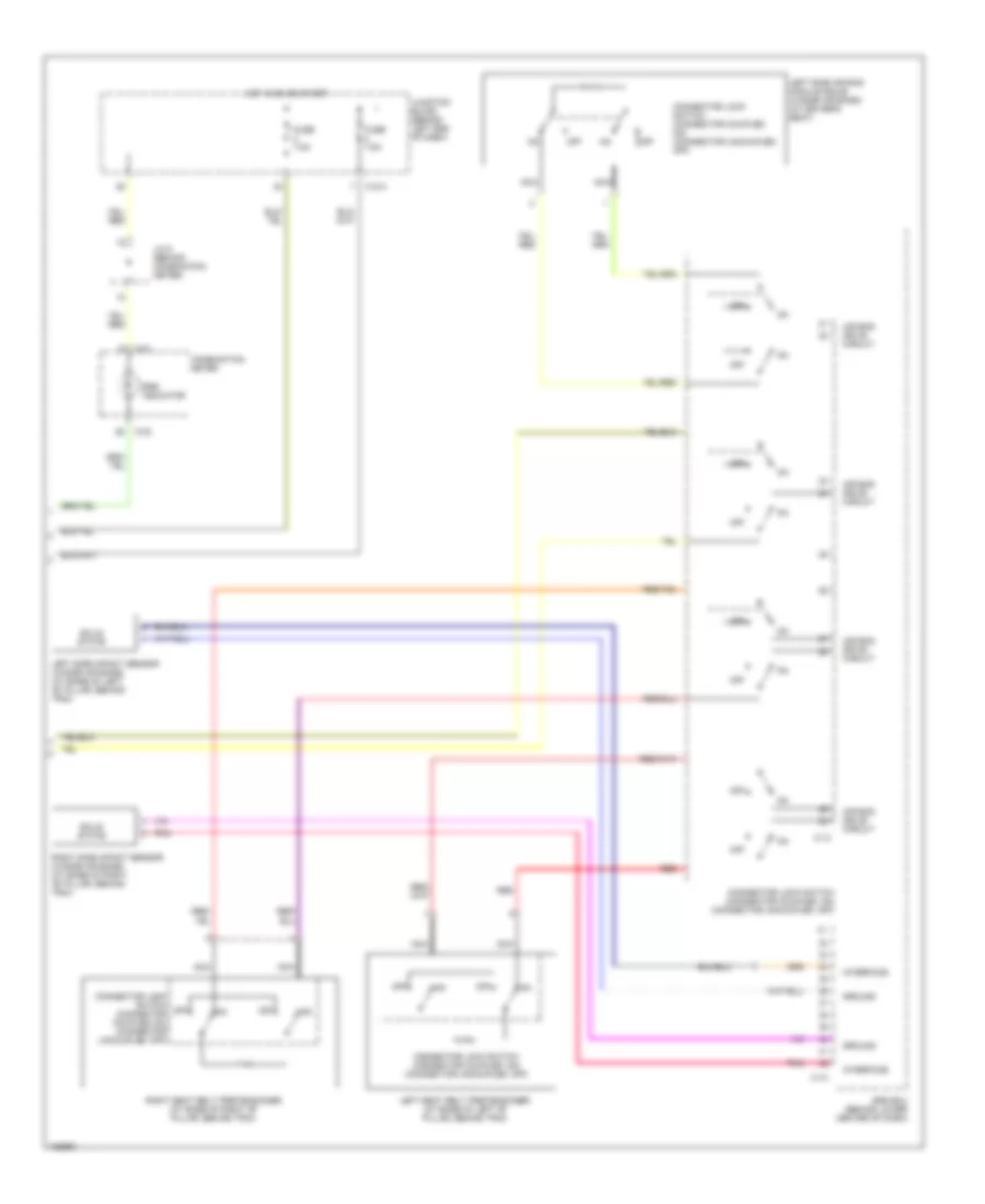
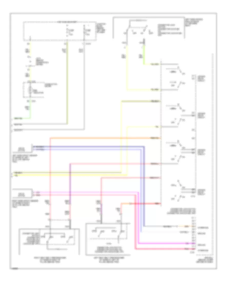
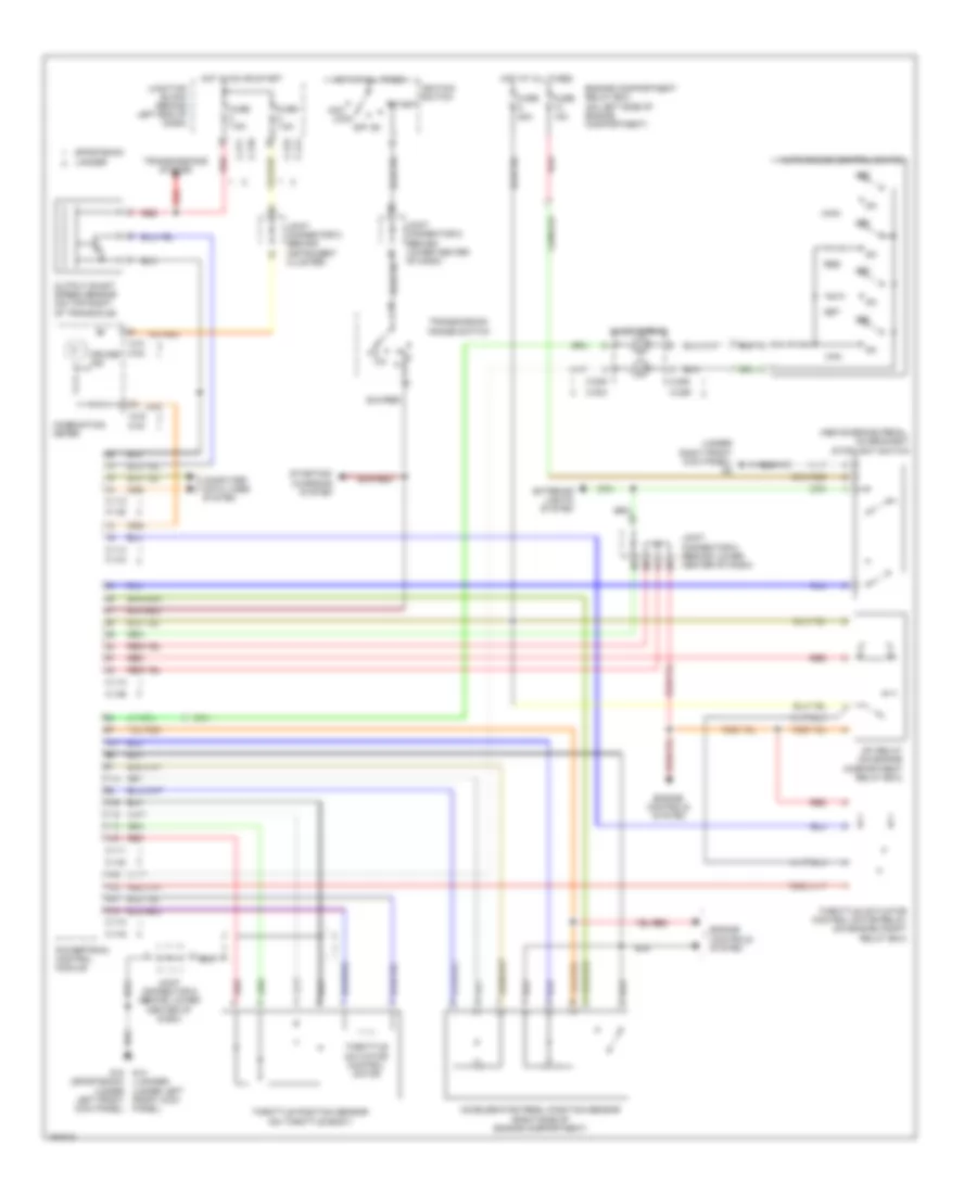
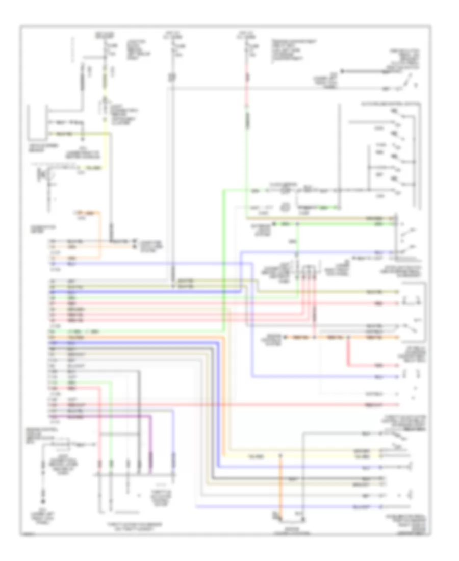
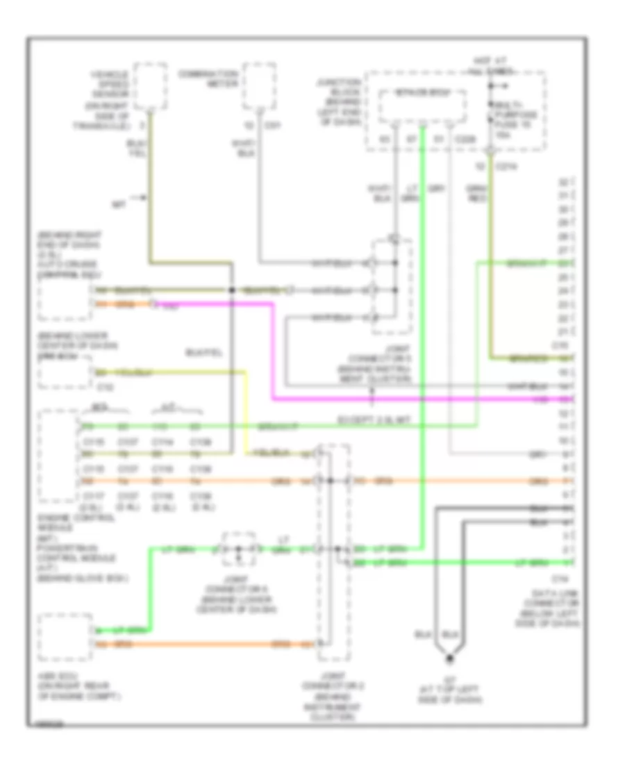
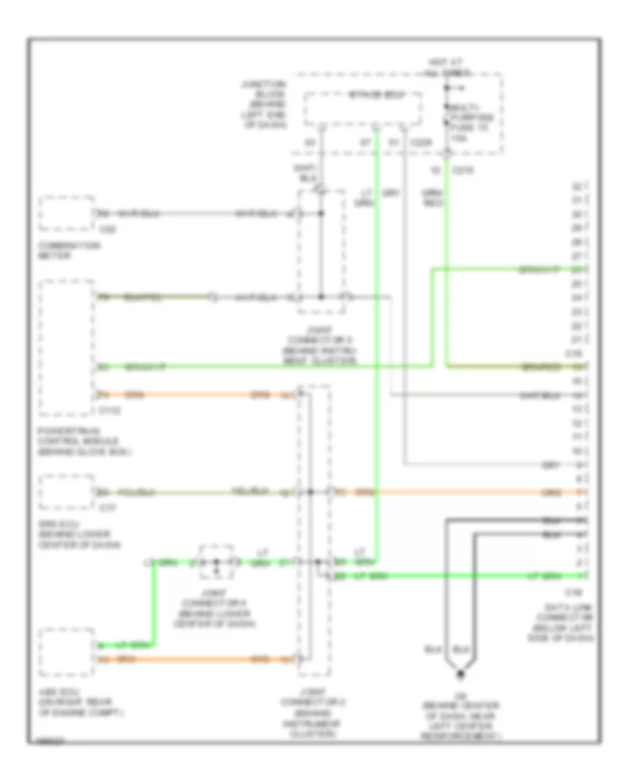
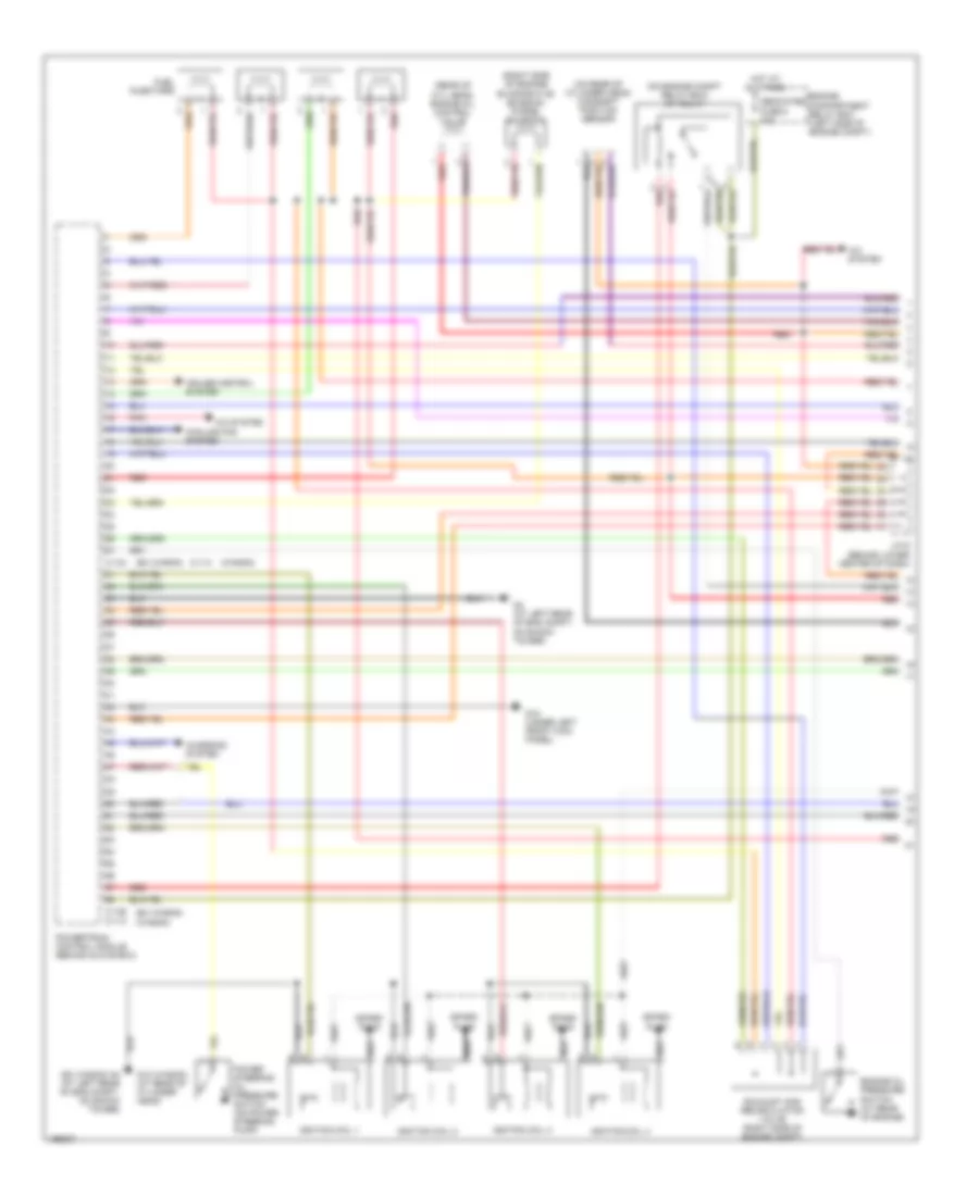
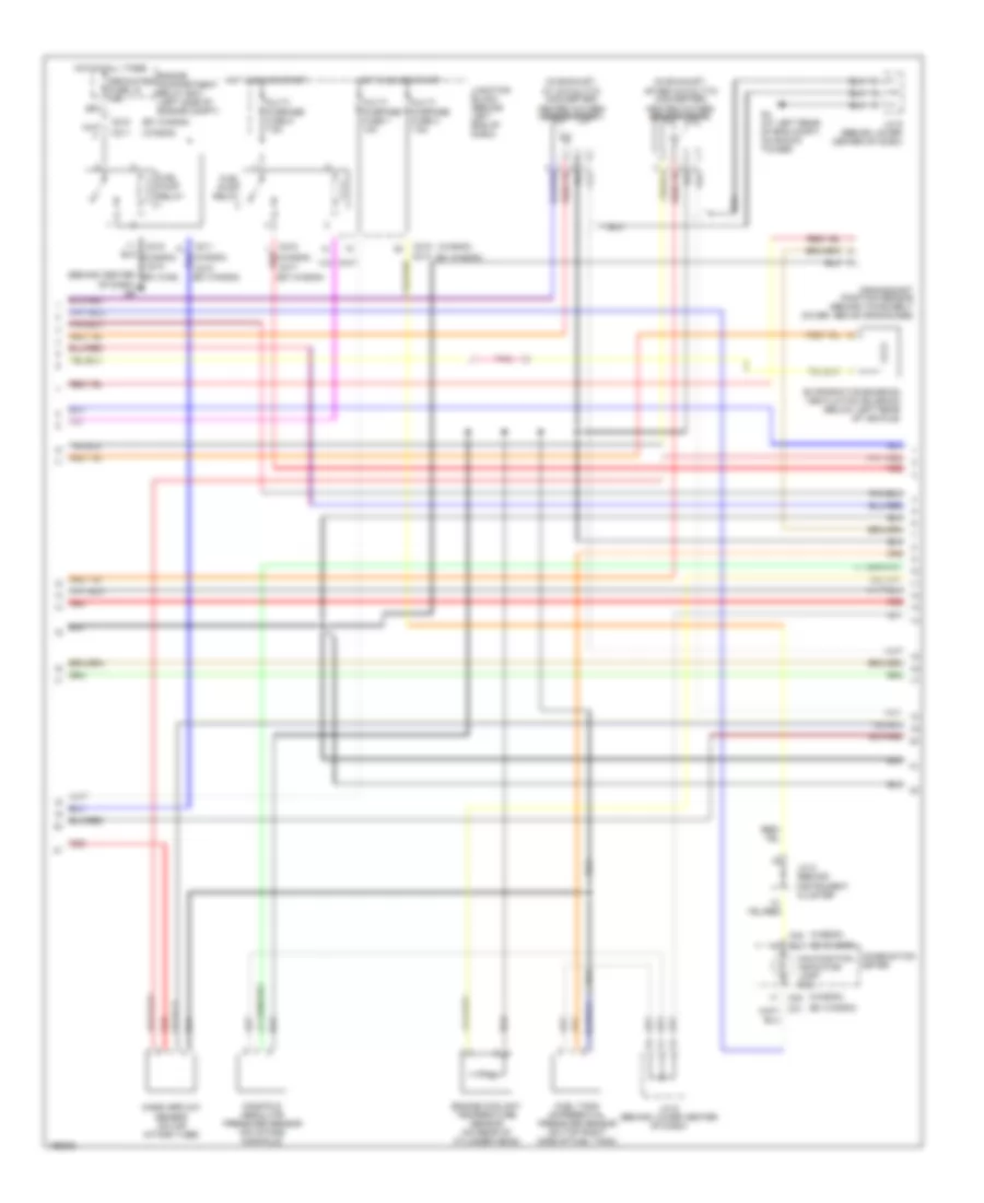
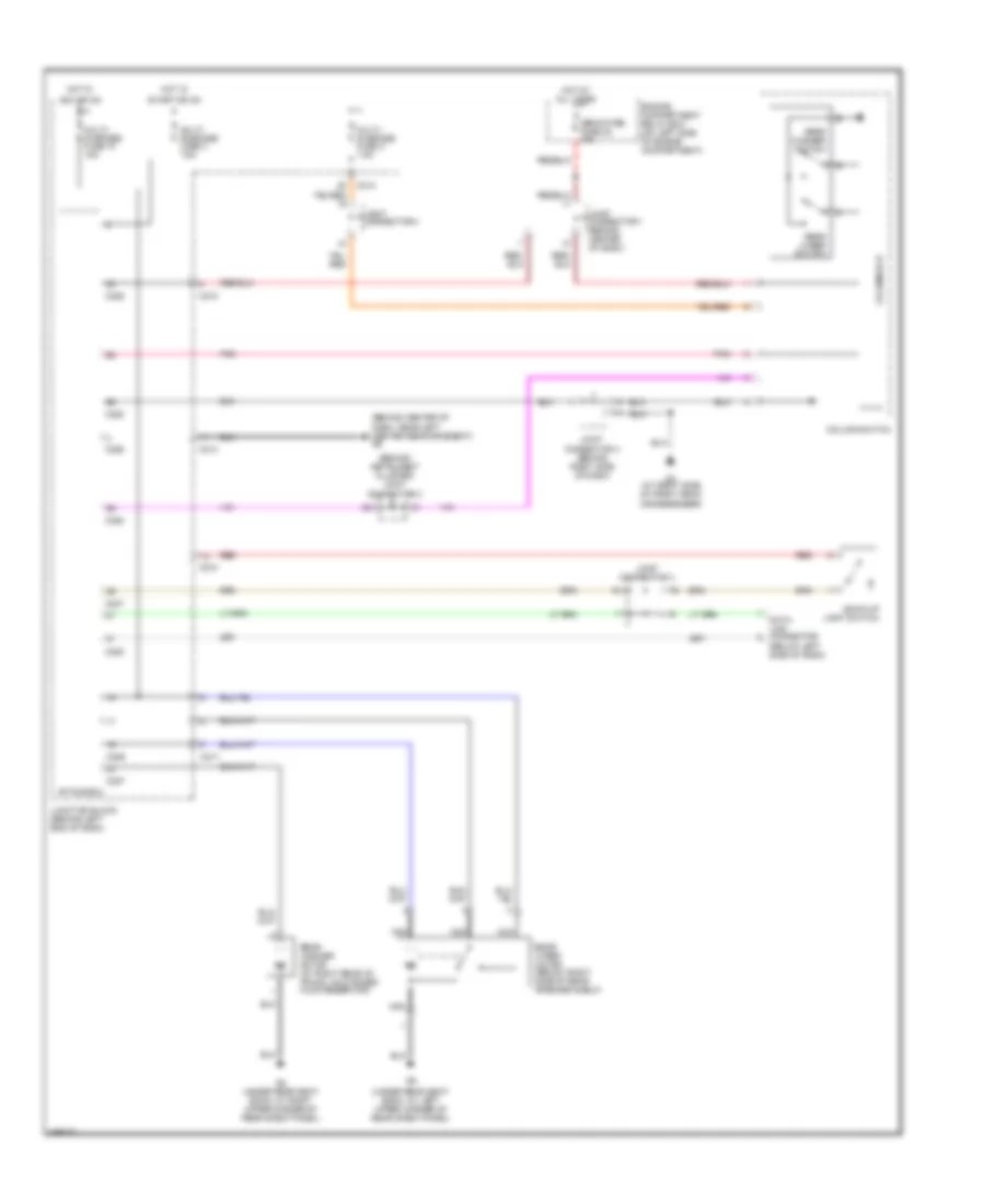
Автомтическая коробка Передач (АКПП) Полная привод (4WD) Блокировка Дифференциала
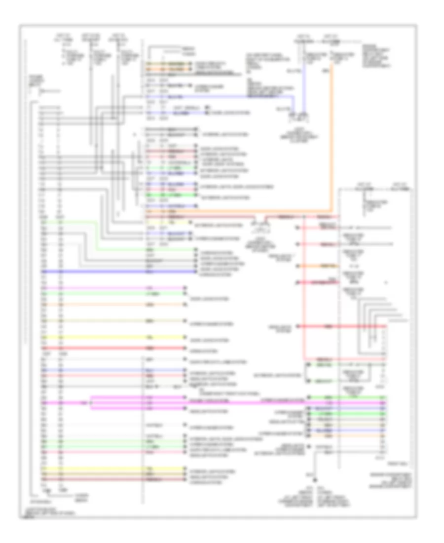
2.0L
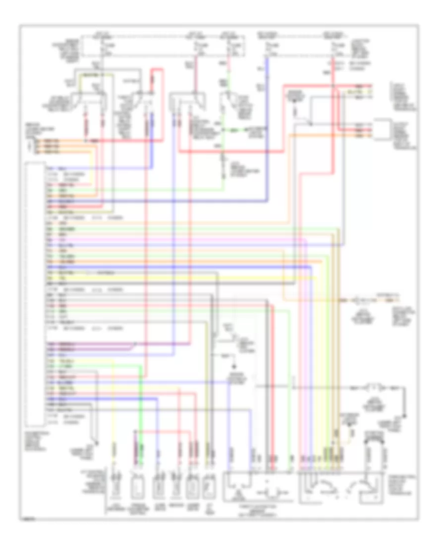
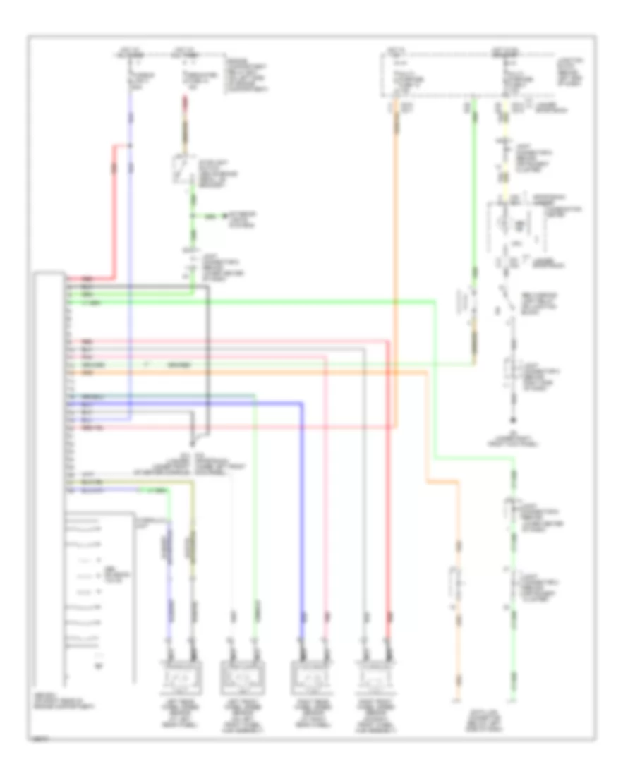
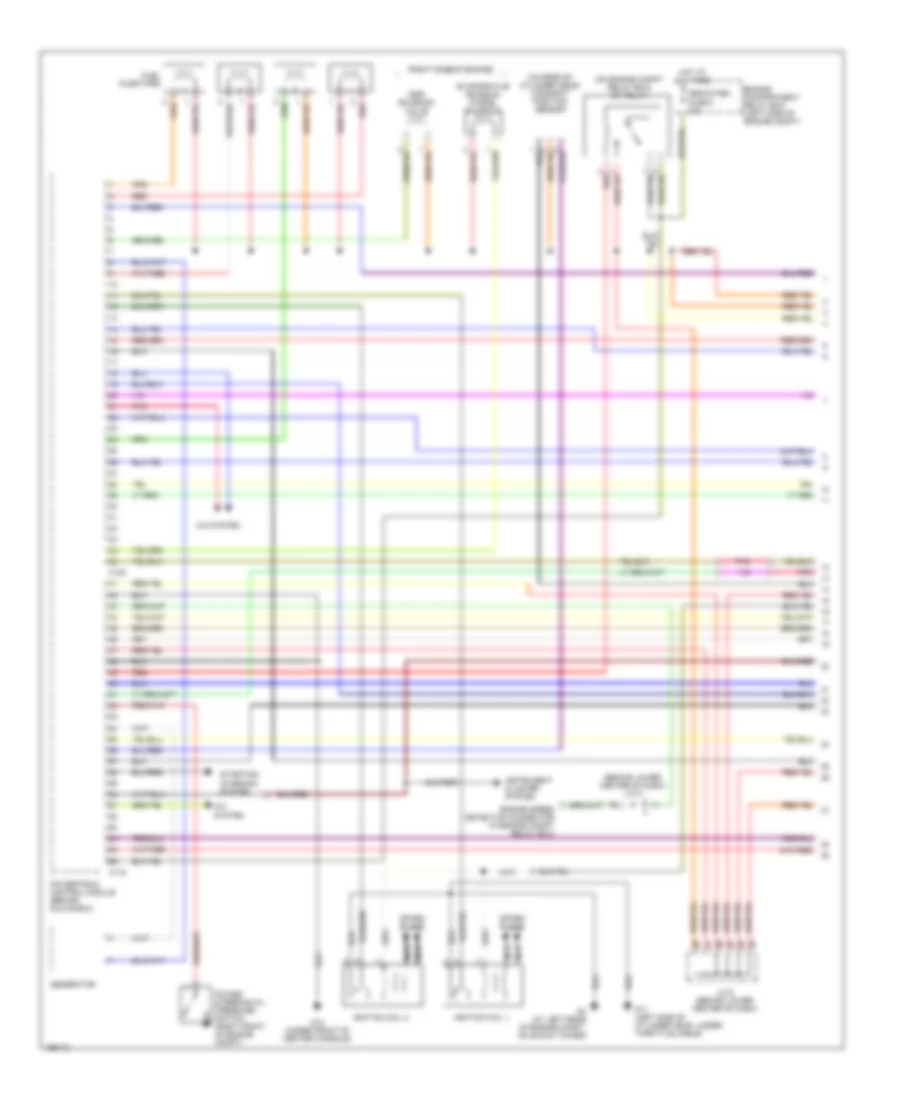
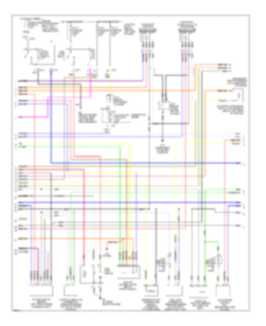
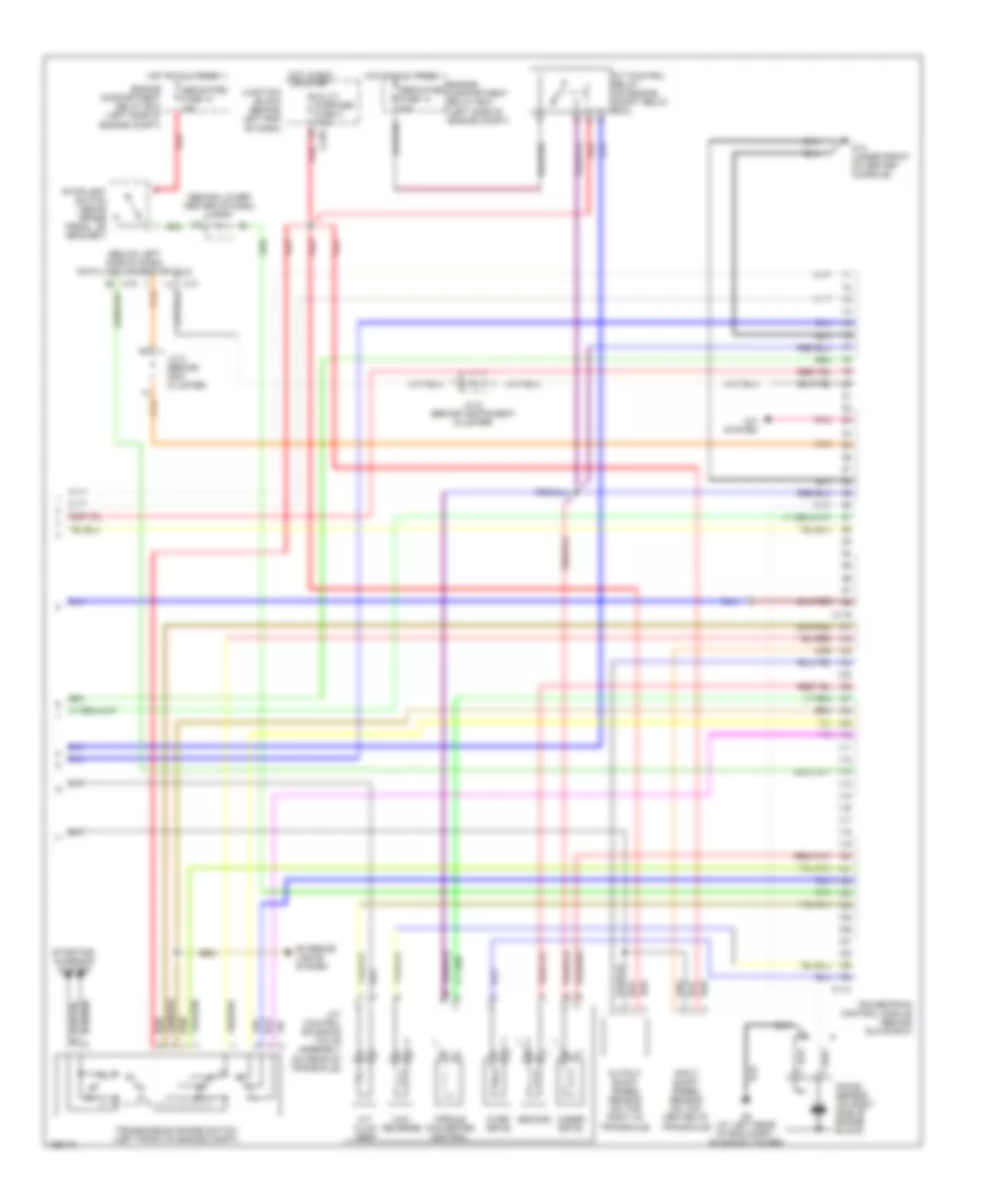
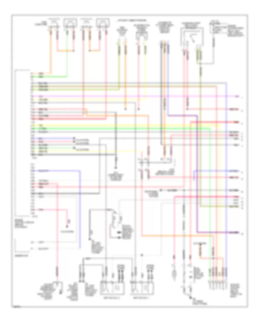
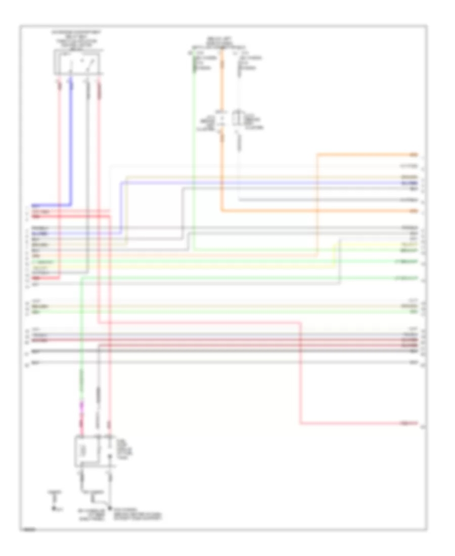
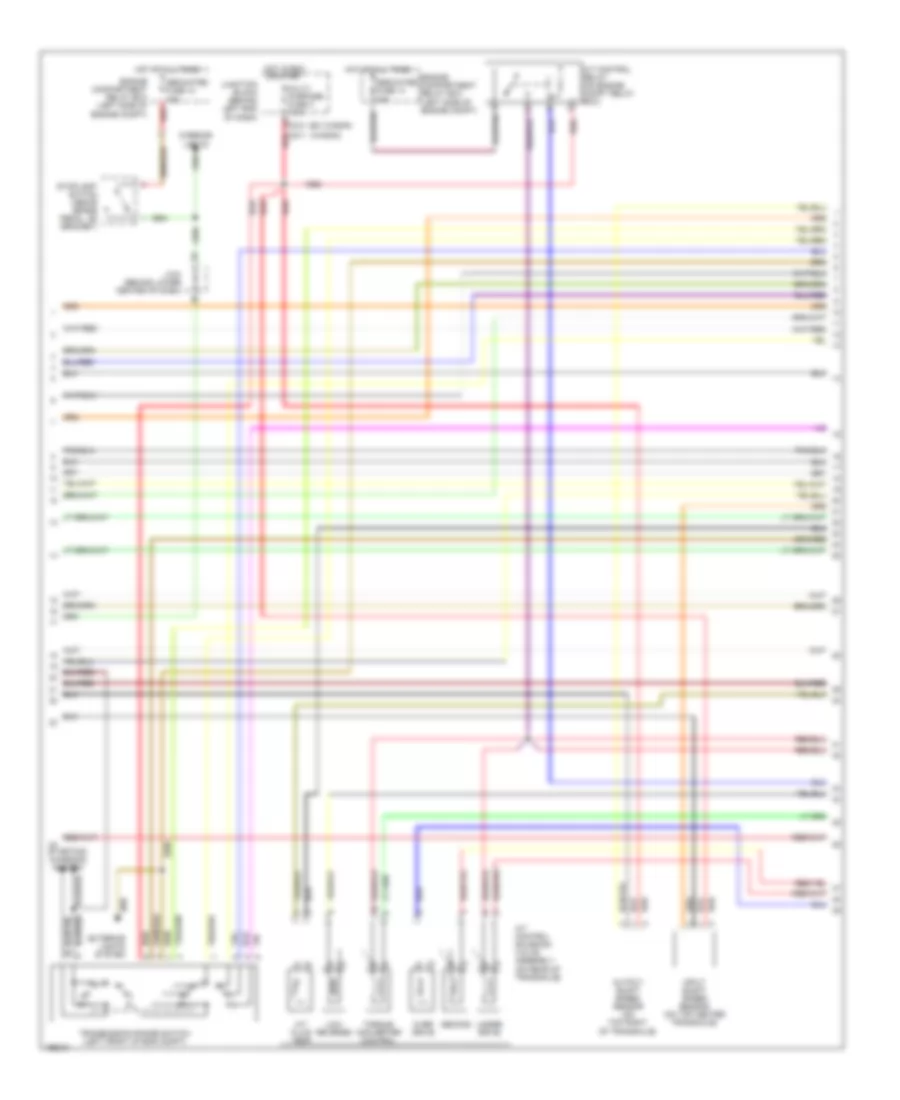
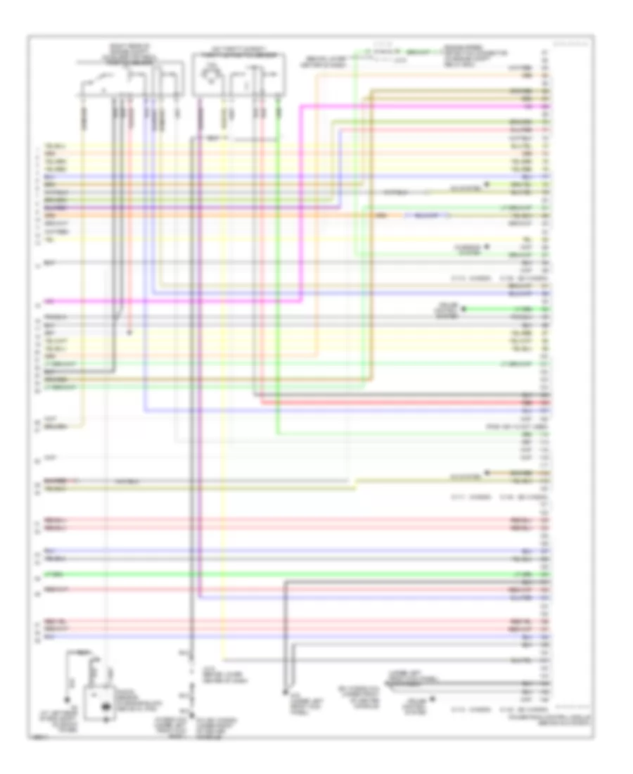
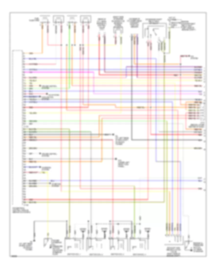
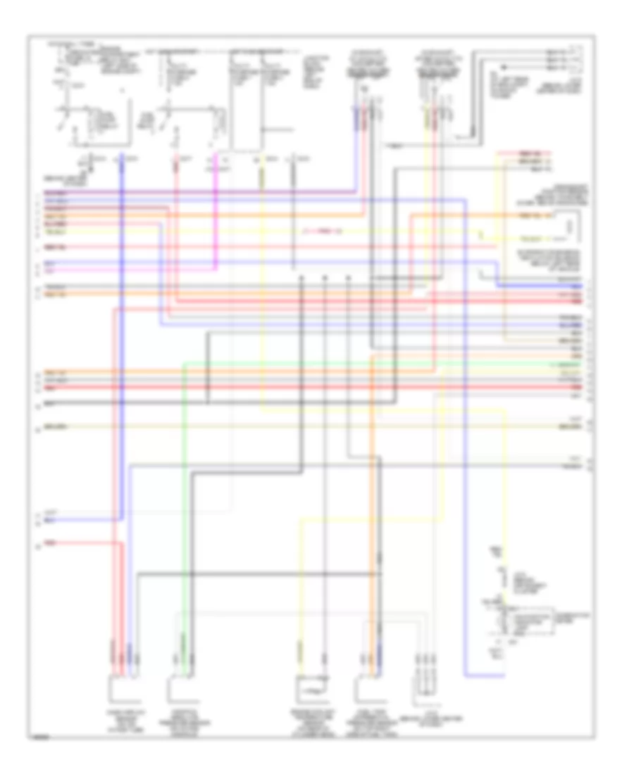
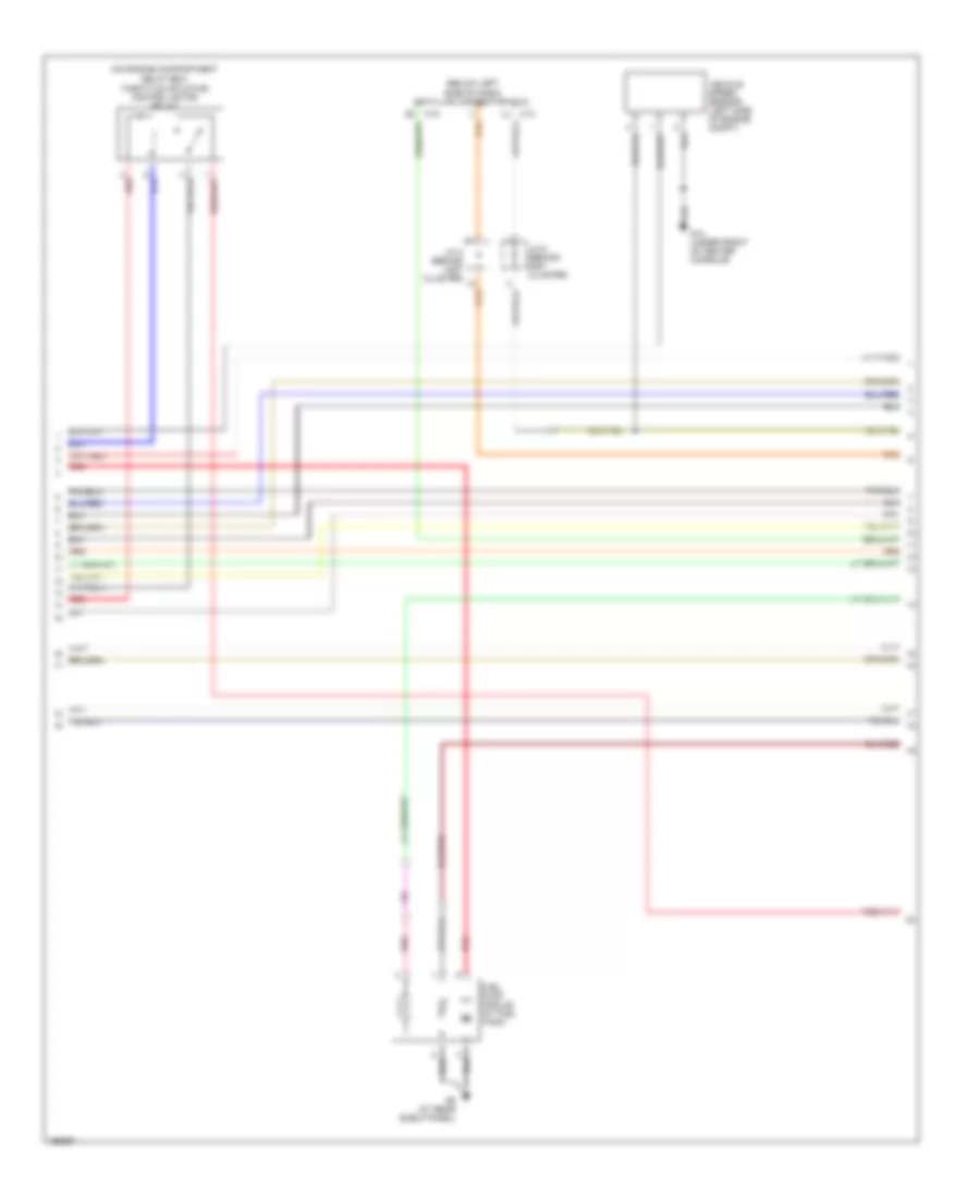
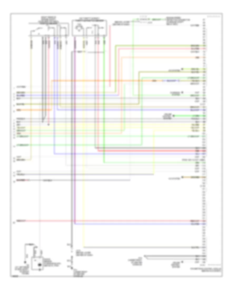
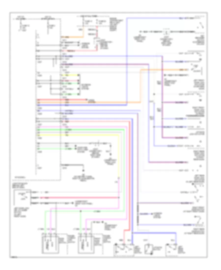
2.0L, Электросхема автоматической коробки передач АКПП для Mitsubishi Lancer Evolution 2004

2.0L, Электросхема автоматической коробки передач АКПП для Mitsubishi Lancer Evolution 2004 - Список элементов:
- (under front of center console) g14
- A/t control relay (on engine compt relay box)
- A/t control solenoid valve assembly (rear of transaxle)
- A/t oil temp
- C-114
- C-116
- C-118
- C-120
- C-210
- Crankshaft position sensor (on lower front of engine)
- Data link connector (below left side of dash)
- Engine compartment relay box (left side of engine compt)
- Engine controls system
- Engine coolant temperature sensor (rear of cyl head)
- Exterior lights system
- Fuse 15a
- Fuse 20a
- Fuse 7.5a
- Hot at all times
- Hot in run or start
- Input shaft speed sensor (on top center of transaxle)
- J/c 2 (behind instrument cluster)
- J/c 5 (behind inst clster)
- J/c 6 (behind lower center of dash)
- Junction block (behind left end of dash)
- Low/ reverse
- Mfi relay (on engine compartment relay box)
- Output shaft speed sensor (top right of transaxle)
- Over drive
- Park/neutral position switch (top of transaxle)
- Powertrain control module (behind glove box)
- Red
- Second
- Starting/ charging system
- Stop light switch (above brake pedal)
- Throttle position sensor (on throttle body)
- Torque converter control
- Under drive
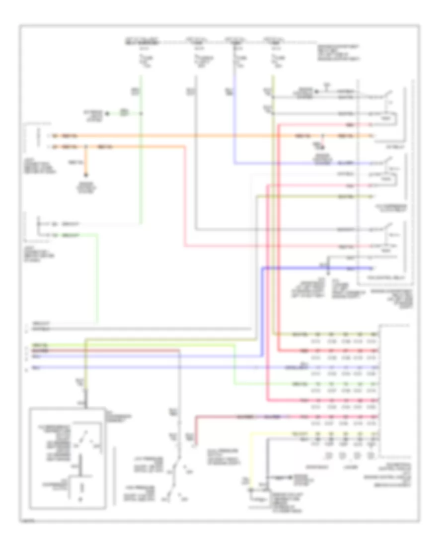
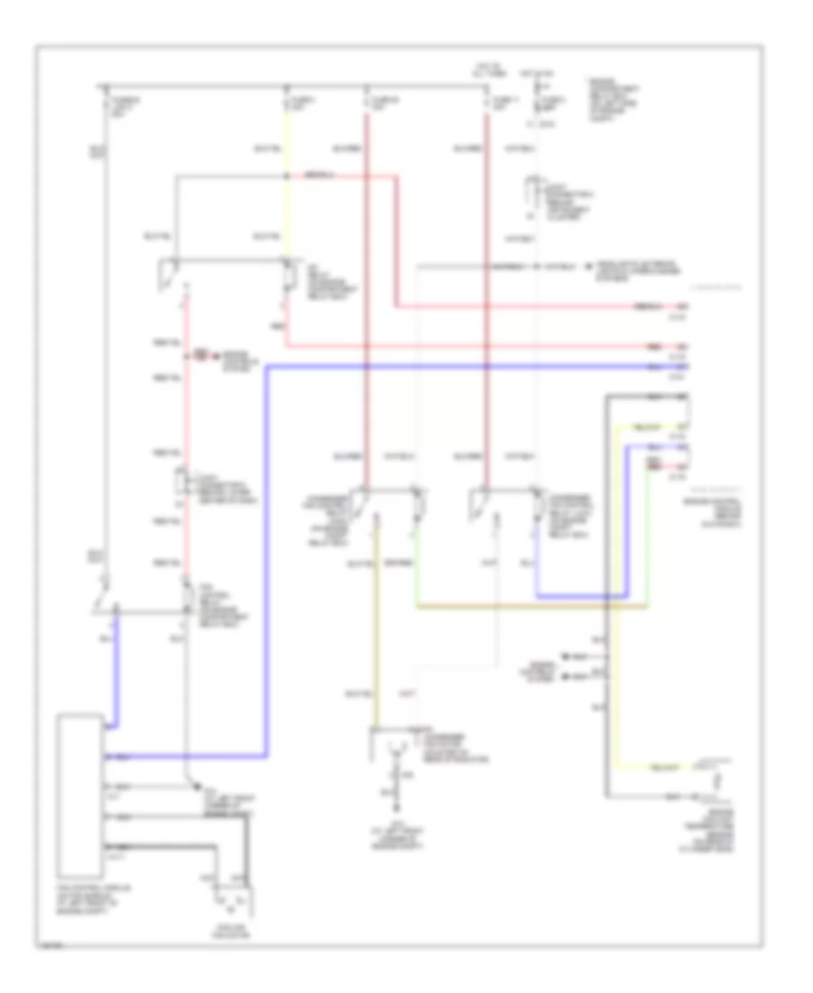
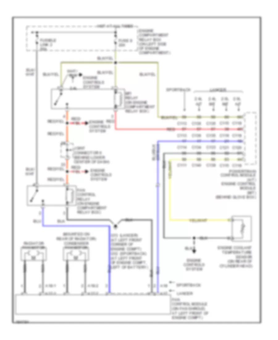
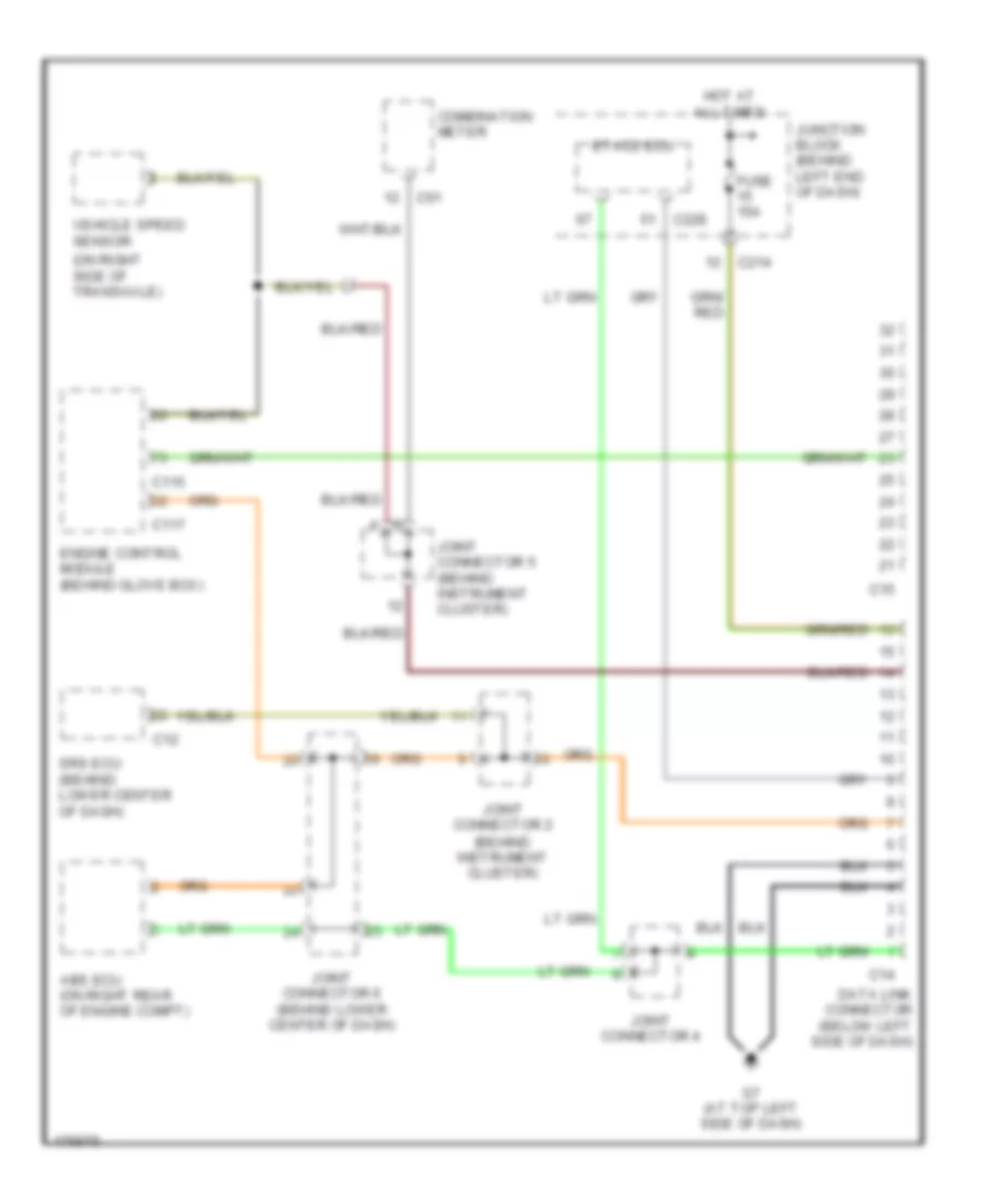
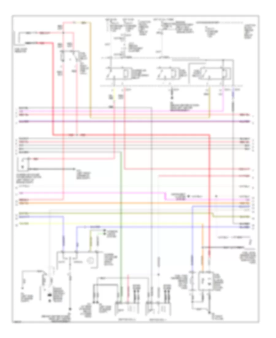
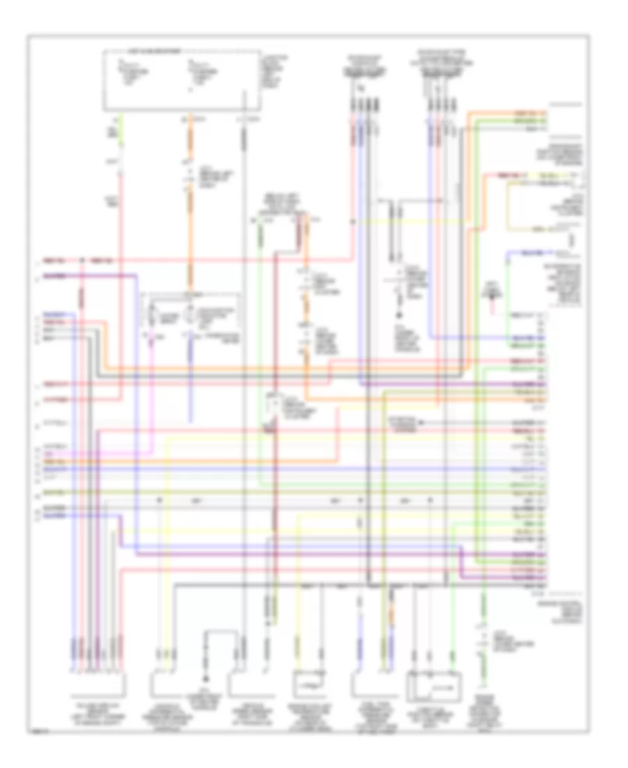
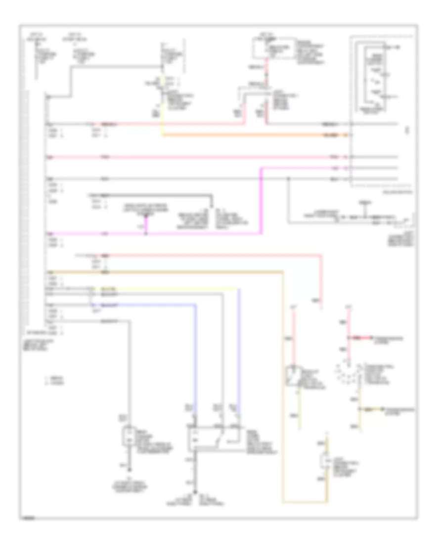
2.4L
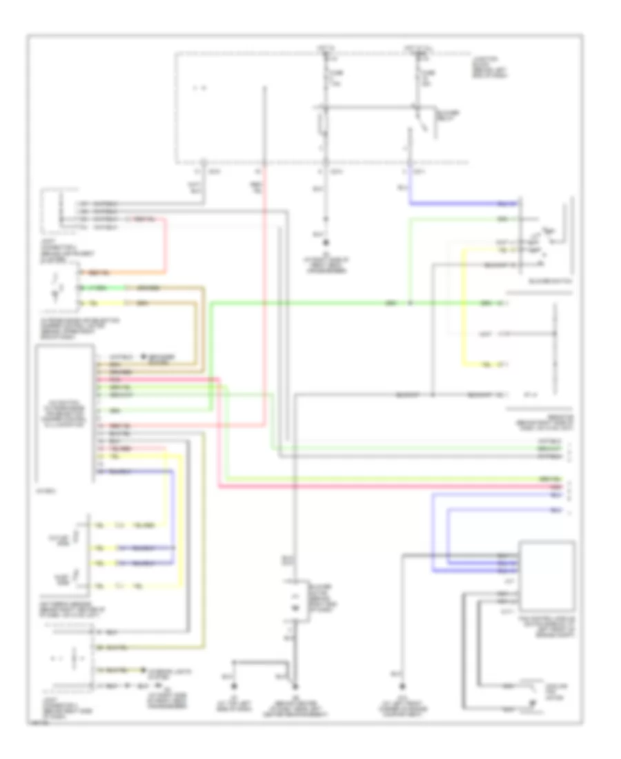
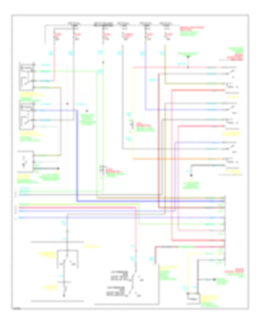
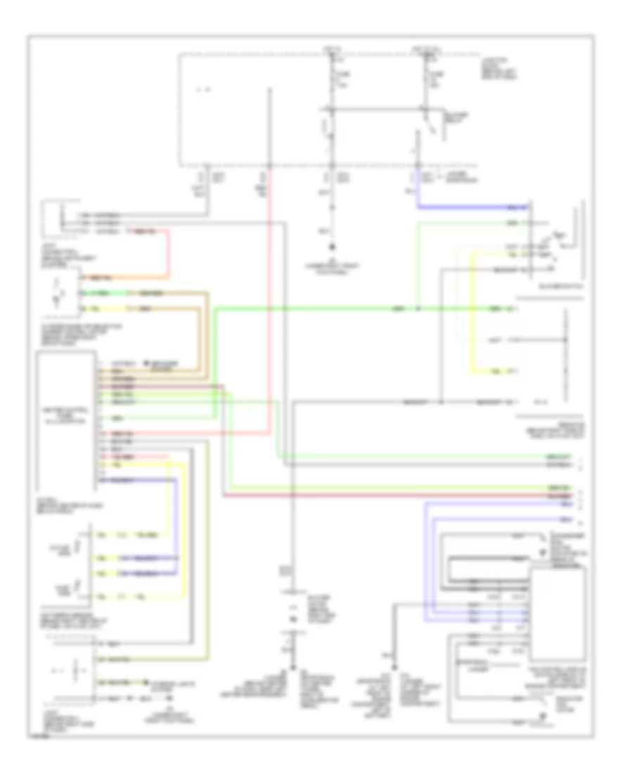
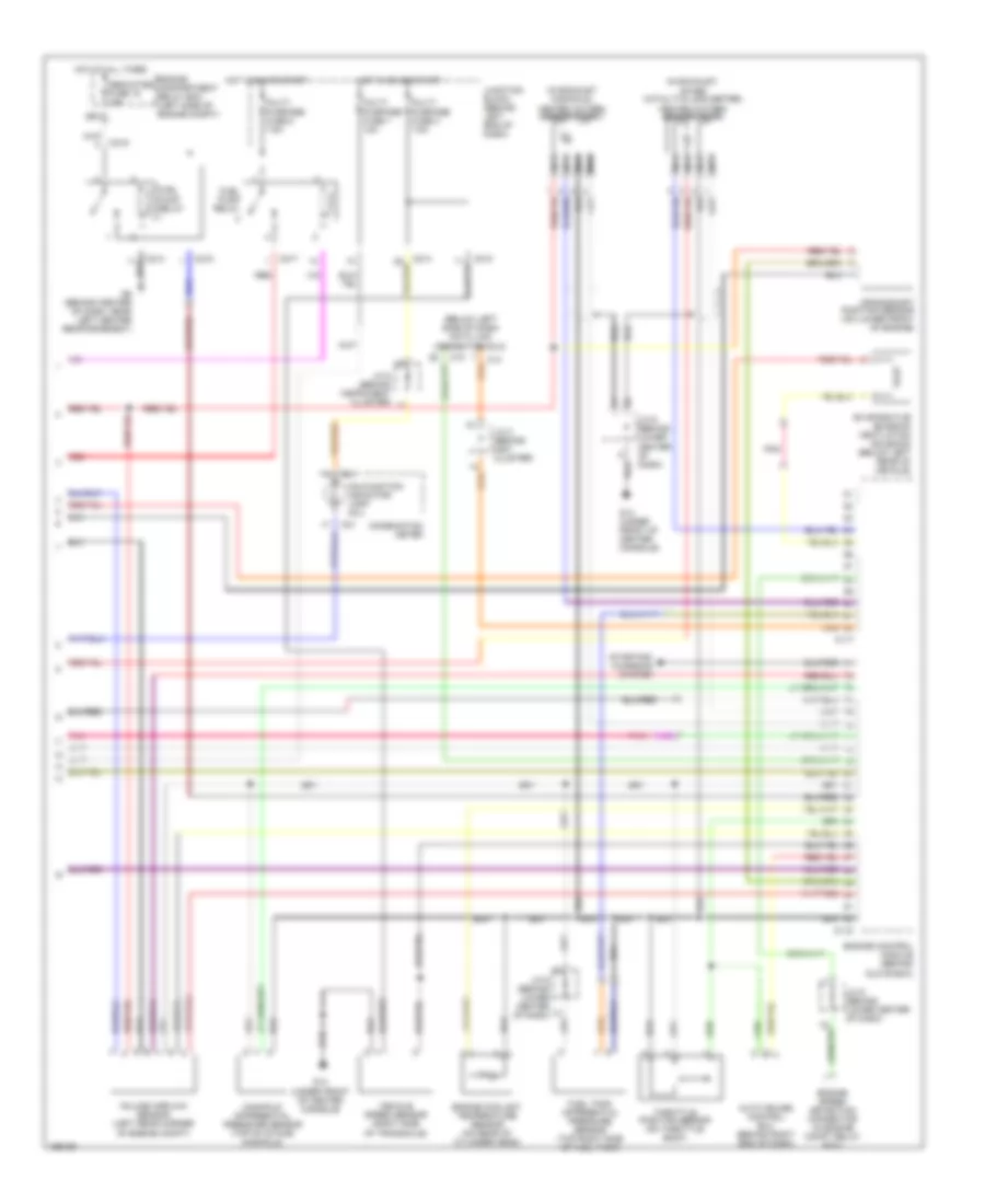
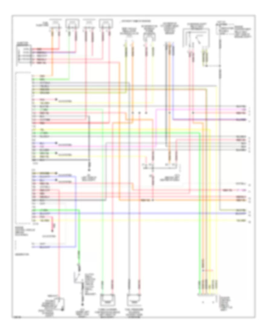
2.4L, Электросхема автоматической коробки передач АКПП для Mitsubishi Lancer Evolution 2004
2.4L, Электросхема автоматической коробки передач АКПП для Mitsubishi Lancer Evolution 2004 - Список элементов:
- (behind lower center of dash) j/c 6
- (ex wagon)
- (wagon)
- A/t control relay (on engine compartment relay box)
- A/t control solenoid valve assembly (rear of transaxle)
- A/t oil temp
- C-110
- C-111
- C-112
- C-113
- C-114
- C-134
- C-136
- C-138
- C-140
- C-142
- C-210
- C-211
- Data link connector (below left side of dash)
- Engine compartment relay box (left side of engine compt)
- Engine controls system
- Exterior lights system
- Fuse 15a
- Fuse 20a
- Fuse 7.5a
- G15 (under left front kick panel)
- Hot at all times
- Hot in run or start
- Input shaft speed sensor (top of center of transaxle)
- J/c 2 (behind instrument cluster)
- J/c 5 (behind inst clster)
- J/c 6 (behind instrument cluster)
- J/c 6 (behind lower center of dash)
- Junction block (behind left end of dash)
- Low/ reverse
- Mfi relay (on engine compartment relay box)
- Output shaft speed sensor (top of right of transaxle)
- Over drive
- Park/neutral position switch (top of transaxle)
- Powertrain control module (behind glove box)
- Red
- Second
- Starting/ charging system
- Stop light switch (above brake pedal)
- Tac motor
- Throt- tle actu- ator control motor relay (on eng compt relay box)
- Throttle position sensor (on throttle body)
- Torque converter control
- Under drive
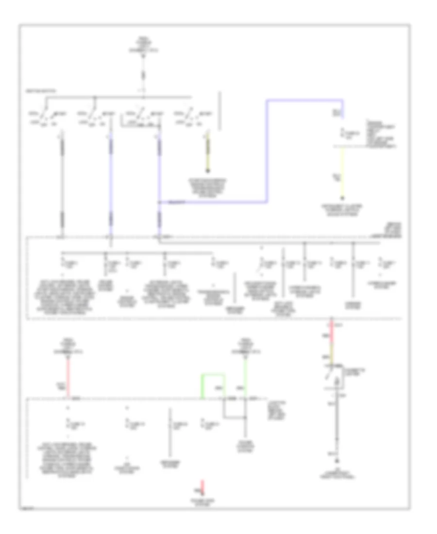
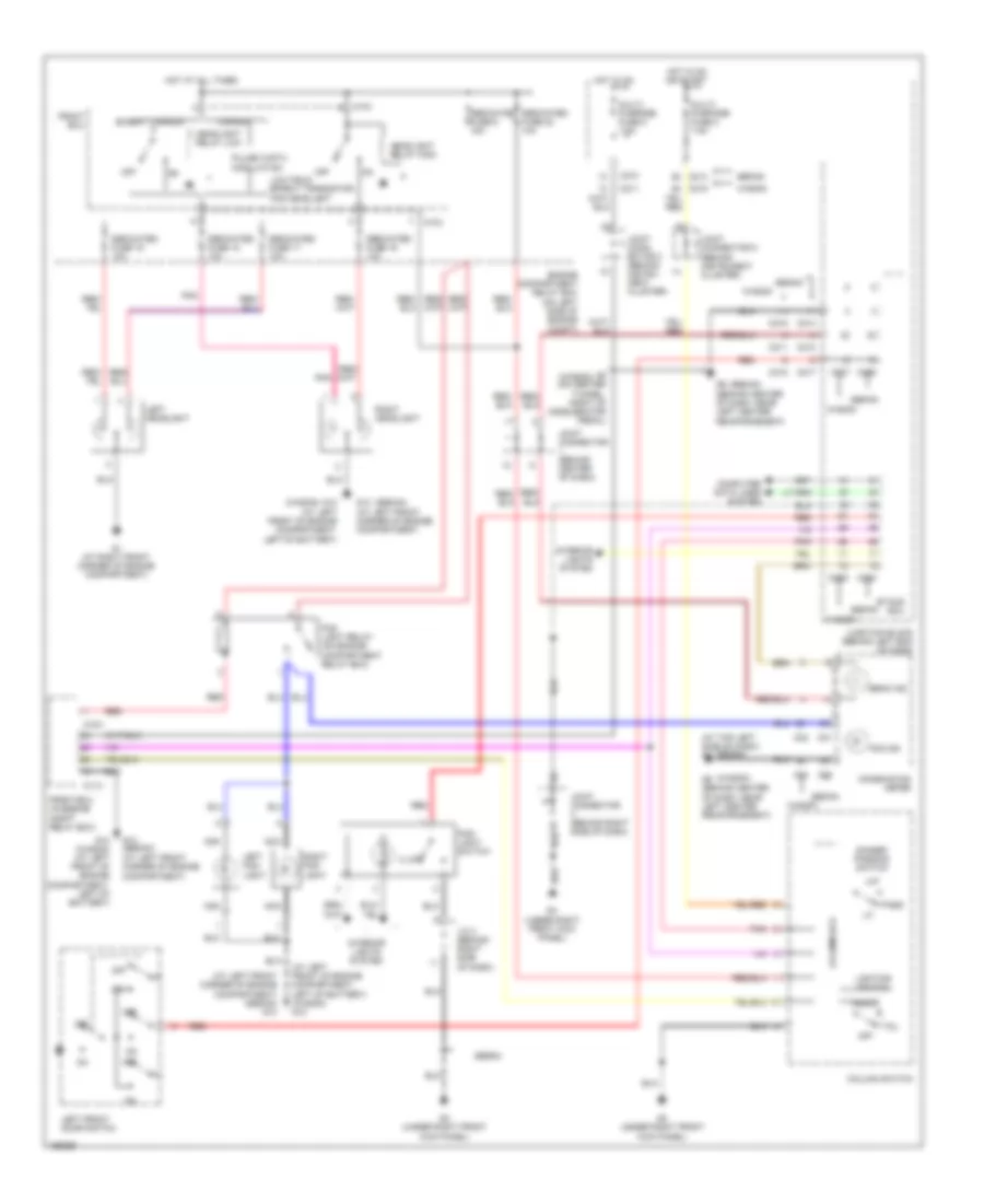
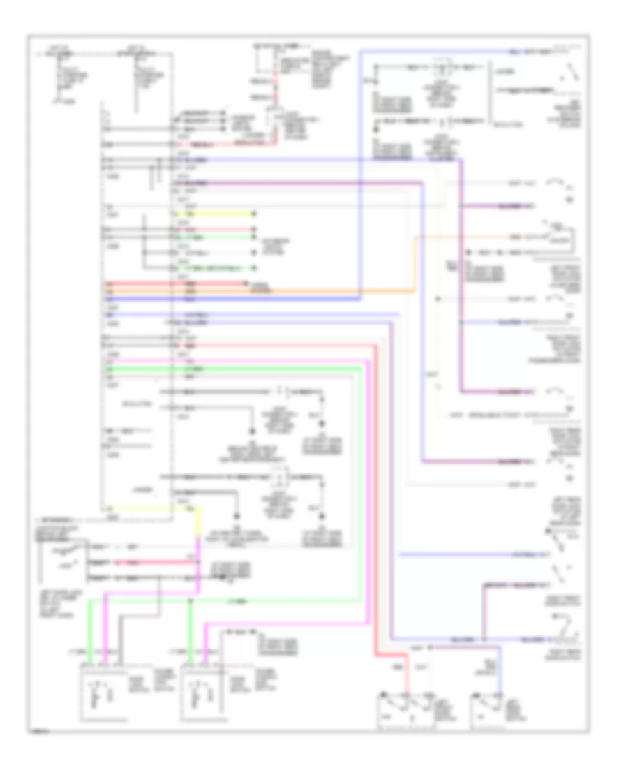
БЛОК ПРЕДОХРАНИТЕЛЕЙ И РЕЛЕ
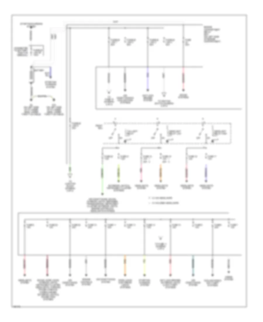
Электросхема блока предохранителей и реле, эволюция (1 из 2) для Mitsubishi Lancer Evolution 2004
Электросхема блока предохранителей и реле, эволюция (1 из 2) для Mitsubishi Lancer Evolution 2004 - Список элементов:
- (connected to battery positive terminal)
- 20a
- Air conditioning & cooling fans systems
- Air conditioning system
- Air conditioning, sound, interior lights, defogger, transmissions, instrument cluster, exterior lights, engine controls & headlights systems
- Anti-lock brakes system
- Anti-lock brakes, exterior lights & anti-theft systems
- Battery
- Cooling fans & anti-theft systems
- Door locks & exterior lights systems
- Engine compartment relay box (on left side of engine compartment)
- Engine controls system
- Exterior lights & instrument cluster systems
- Front ecu
- Fuse 10 15a
- Fuse 11 30a
- Fuse 12 7.5a
- Fuse 13 10a
- Fuse 15 20a
- Fuse 16 10a
- Fuse 17 10a
- Fuse 18 10a
- Fuse 19 10a
- Fuse 20 7.5a
- Fuse 20a
- Fuse 21 7.5a
- Fuse 22 10a
- Fuse 25 30a
- Fuse 6 15a
- Fuse 7 10a
- Fuse 8 20a
- Fuse 9 10a
- Fusible link 1 60a
- Fusible link 2 50a
- Fusible link 26 100a
- Fusible link 3 60a
- Fusible link 4 40a
- Fusible link 5 30a
- G10 (on left side of cylinder head, under throttle cable)
- G4 (on left side of cylinder head, under throttle cable)
- Headlight relay high
- Headlight relay low
- Headlights system
- Horns system
- Off
- Pnk
- Red
- Sound systems
- Sound, door locks, interior lights, instrument cluster, headlights, warning, power windows, wiper/washer, exterior lights & power tops systems
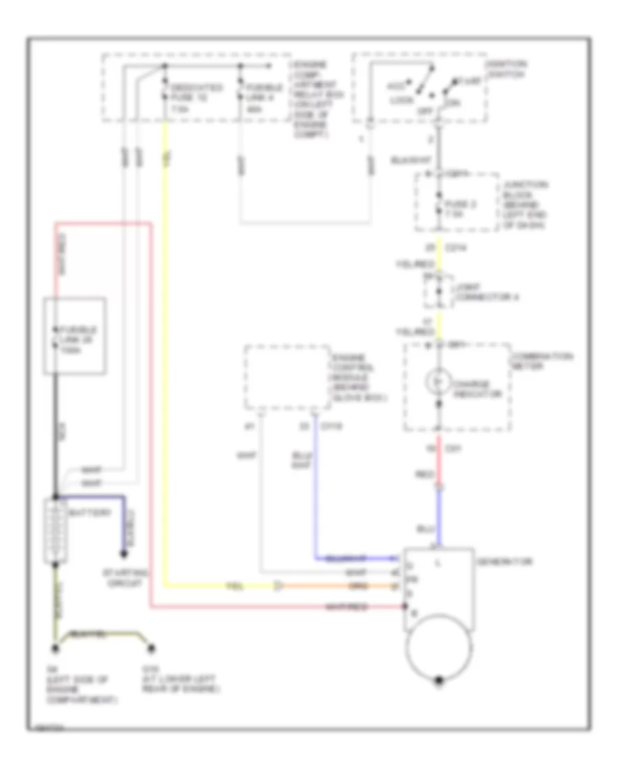
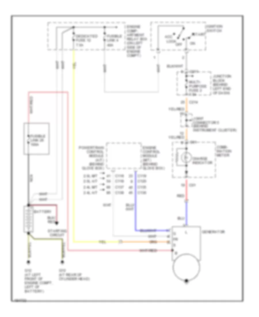
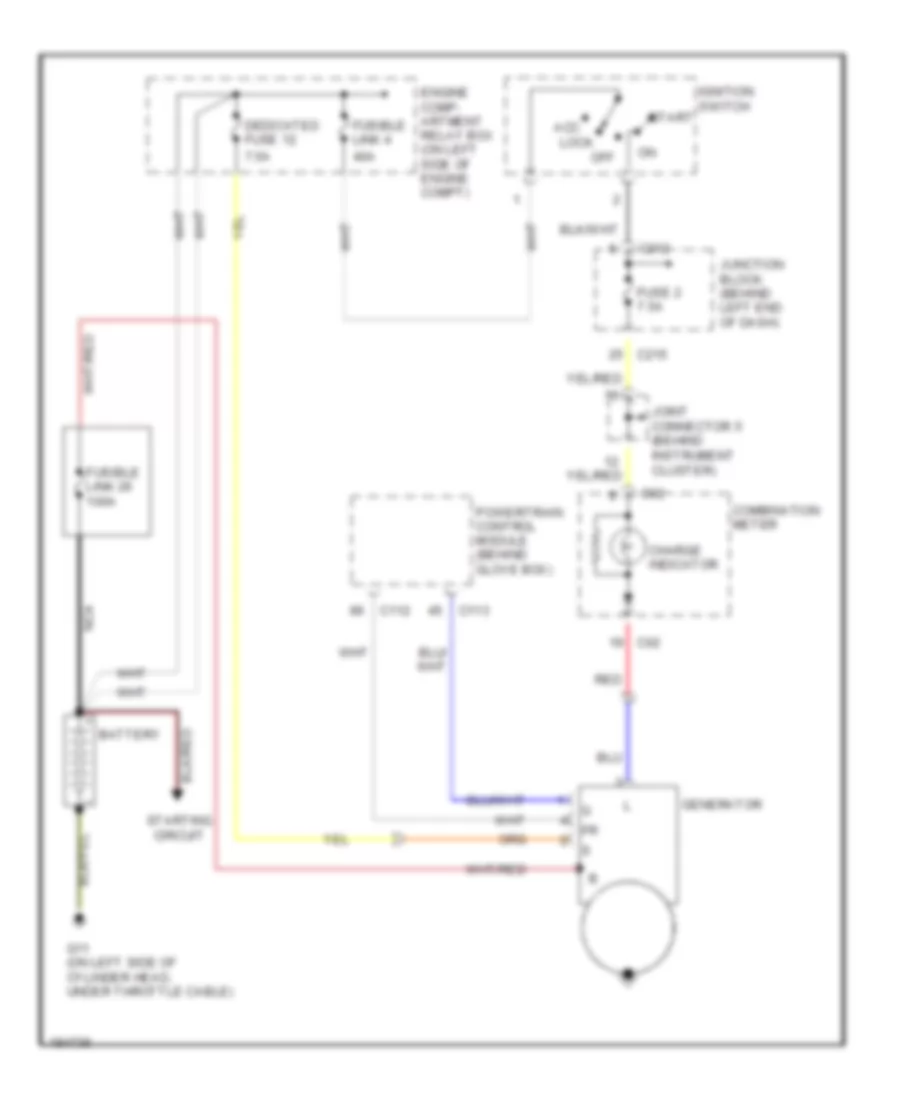
- Starting/ charging system
- Starting/charging system
- Taillight relay
- To fuse 11 (diagram 2 of 2)
- To fuse 15 (diagram 2 of 2)
- To ignition switch (diagram 2 of 2)
- To junction block (diagram 2 of 2)
- W/ halogen headlamps
- W/ hid headlamps
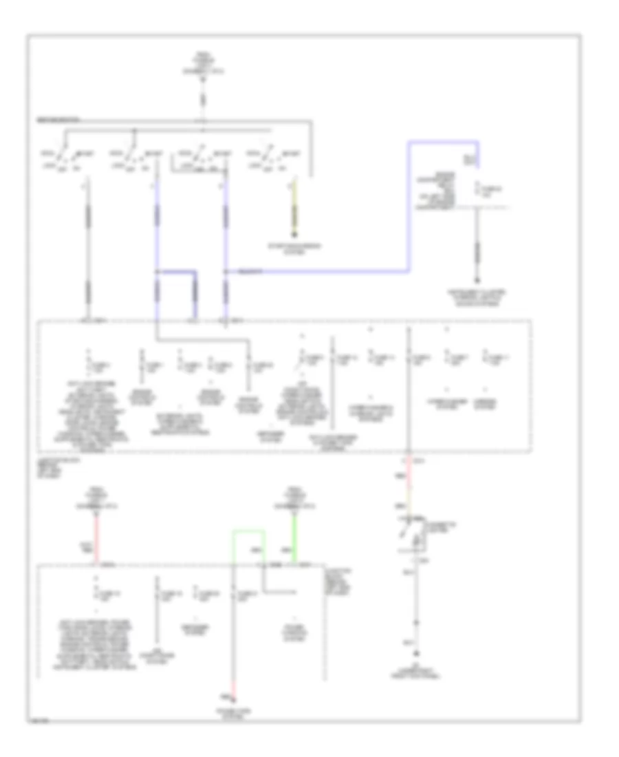
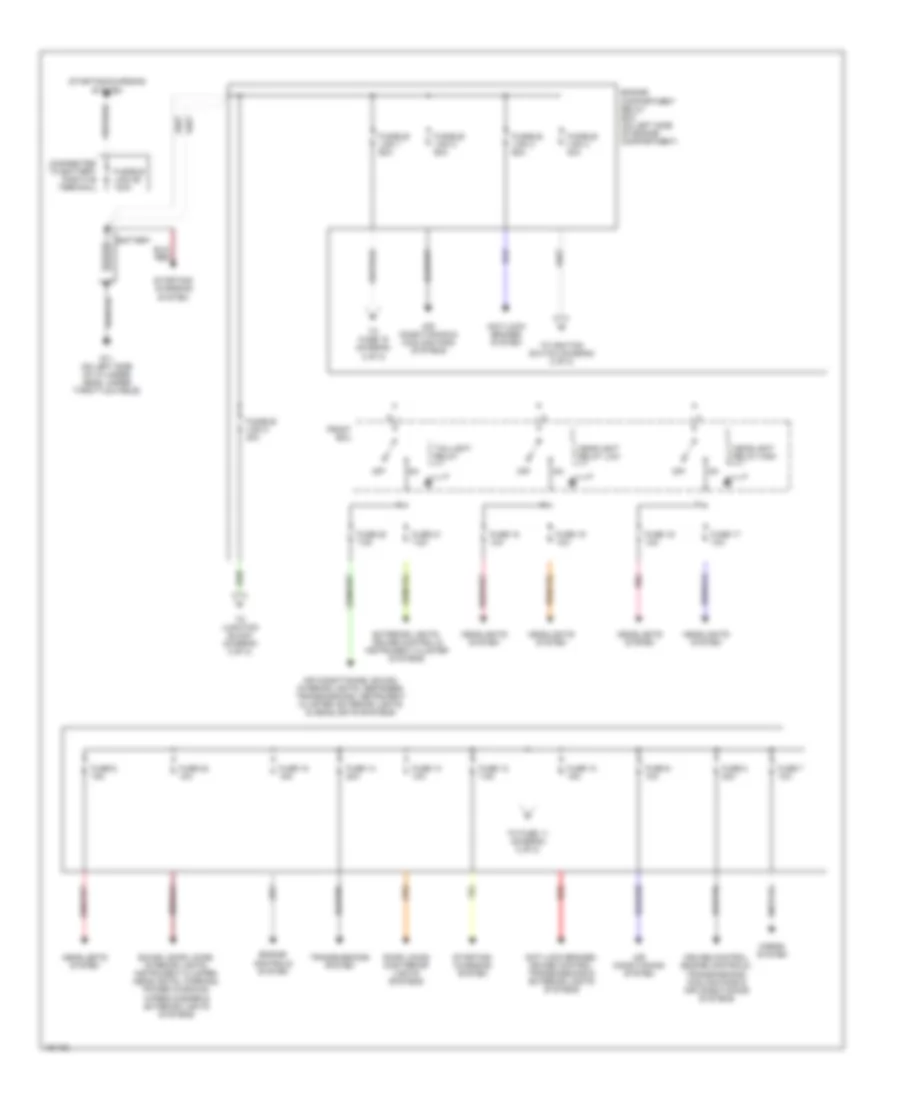
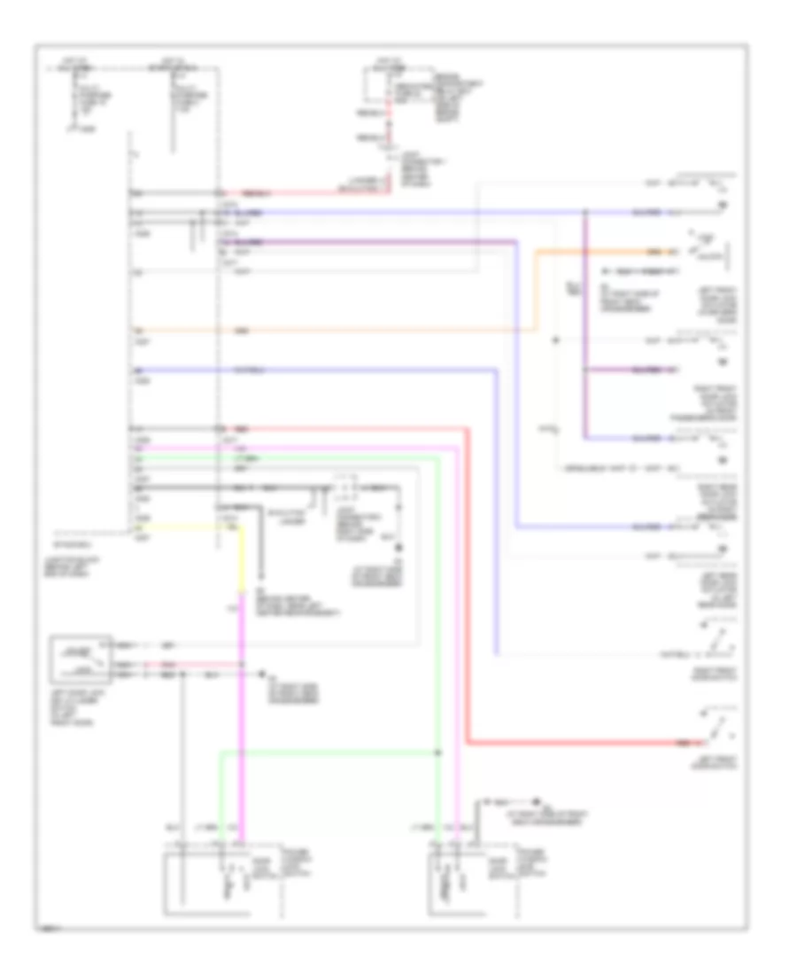
Электросхема блока предохранителей и реле, эволюция (2 из 2) для Mitsubishi Lancer Evolution 2004
Электросхема блока предохранителей и реле, эволюция (2 из 2) для Mitsubishi Lancer Evolution 2004 - Список элементов:
- Acc
- Air conditioning system
- Air conditioning, wiper/washer, headlights & exterior lights, engine controls & anti-lock brakes systems
- Anti-lock brakes & power tops systems
- C211
- C212
- C214
- C225
- Cigarette lighter
- D23
- D24
- Defogger system
- Defogger system
- Engine compartment relay box (on left side of engine compartment)
- Engine controls system
- From fusible link 1 (diagram 1 of 2)
- From fusible link 4 (diagram 1 of 2)
- From fusible link 5 (diagram 1 of 2)
- Fuse 1 10a
- Fuse 11 7.5a
- Fuse 12 7.5a
- Fuse 14 15a
- Fuse 15 15a
- Fuse 19 30a
- Fuse 2 7.5a
- Fuse 20 30a
- Fuse 21 20a
- Fuse 23 10a
- Fuse 3 7.5a
- Fuse 5 7.5a
- Fuse 7 20a
- Fuse 8 7.5a
- Fuse 9 15a
- G3 (under right front kick panel)
- Ignition switch
- Instrument cluster, interior lights & sound systems
- Junction block (behind left end of dash)
- Lock
- Mirrors system
- Off
- Power tops system
- Power windows system
- Red
- Start
- Starting/charging system
- Wiper/washer & interior lights systems
- Wiper/washer system
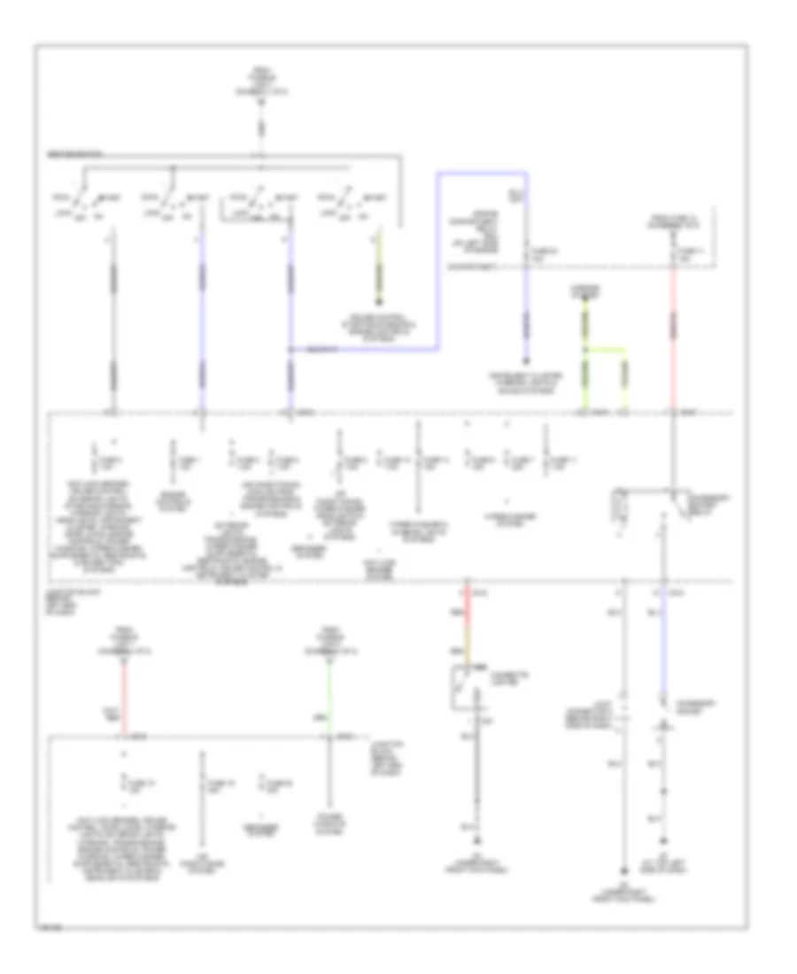
Электросхема блока предохранителей и реле, кроме Универсала или эволюции (1 из 2) для Mitsubishi Lancer Evolution 2004
Электросхема блока предохранителей и реле, кроме Универсала или эволюции (1 из 2) для Mitsubishi Lancer Evolution 2004 - Список элементов:
- (connected to battery positive terminal)
- Air conditioning & cooling fans systems
- Air conditioning system
- Air conditioning, sound, interior lights, defogger, transmissions, instrument cluster, exterior lights & head lights systems
- Anti-lock brakes system
- Anti-lock brakes, cruise control, transmissions & exterior lights systems
- Battery
- Cruise control, engine controls & transmissions systems
- Door locks & exterior lights systems
- Engine compartment relay box (on left side of engine compartment)
- Engine controls system
- Exterior lights, instrument cluster, cruise control & power tops systems
- Front ecu
- Fuse 10 15a
- Fuse 12 7.5a
- Fuse 13 10a
- Fuse 14 20a
- Fuse 15 15a
- Fuse 16 10a
- Fuse 17 10a
- Fuse 18 10a
- Fuse 19 10a
- Fuse 20 7.5a
- Fuse 20a
- Fuse 21 7.5a
- Fuse 22 10a
- Fuse 6 15a
- Fuse 7 10a
- Fuse 8 20a
- Fuse 9 10a
- Fusible link 1 60a
- Fusible link 2 50a
- Fusible link 26 100a
- Fusible link 3 60a
- Fusible link 4 40a
- Fusible link 5 30a
- G10 (at rear of cylinder head)
- G12 (at left front of engine compt, left of battery)
- Headlight relay high
- Headlight relay low
- Headlights system
- Horns system
- Off
- Pnk
- Red
- Sound systems
- Sound, door locks, interior lights, instrument cluster, headlights, warning, power windows, power tops, wiper/washer & exterior lights systems
- Starting/ charging system
- Taillight relay
- To fuse 15 (diagram 2 of 2)
- To ignition switch (diagram 2 of 2)
- To junction block (diagram 2 of 2)
- Transmissions system
Электросхема блока предохранителей и реле, кроме Универсала или эволюции (2 из 2) для Mitsubishi Lancer Evolution 2004
Электросхема блока предохранителей и реле, кроме Универсала или эволюции (2 из 2) для Mitsubishi Lancer Evolution 2004 - Список элементов:
- (behind left end of dash) junction block
- Acc
- Air conditioning system
- Air conditioning, wiper/washer, headlights & exterior lights systems
- Anti-lock brakes & power tops system
- C211
- C212
- C214
- C225
- Cigarette lighter
- Cruise control system
- D23
- D24
- Defogger system
- Engine compartment relay box (on left side of engine compartment)
- Engine controls system
- From fusible link 1 (diagram 1 of 2)
- From fusible link 4 (diagram 1 of 2)
- From fusible link 5 (diagram 1 of 2)
- Fuse 1 10a
- Fuse 11 7.5a
- Fuse 12 7.5a
- Fuse 14 15a
- Fuse 15 15a
- Fuse 19 30a
- Fuse 2 7.5a
- Fuse 20 30a
- Fuse 21 20a
- Fuse 23 10a
- Fuse 3 7.5a
- Fuse 4 7.5a (2.0l)
- Fuse 5 7.5a
- Fuse 7 20a
- Fuse 8 7.5a
- Fuse 9 15a
- G3 (under right front kick panel)
- Ignition switch
- Instrument cluster, interior lights & sound systems
- Junction block (behind left end of dash)
- Lock
- Mirrors system
- Off
- Power tops system
- Power windows system
- Red
- Start
- Starting/charging, engine controls, transmissions & cruise control systems
- Transmissions & engine controls systems
- Wiper/washer & interior lights systems
- Wiper/washer system
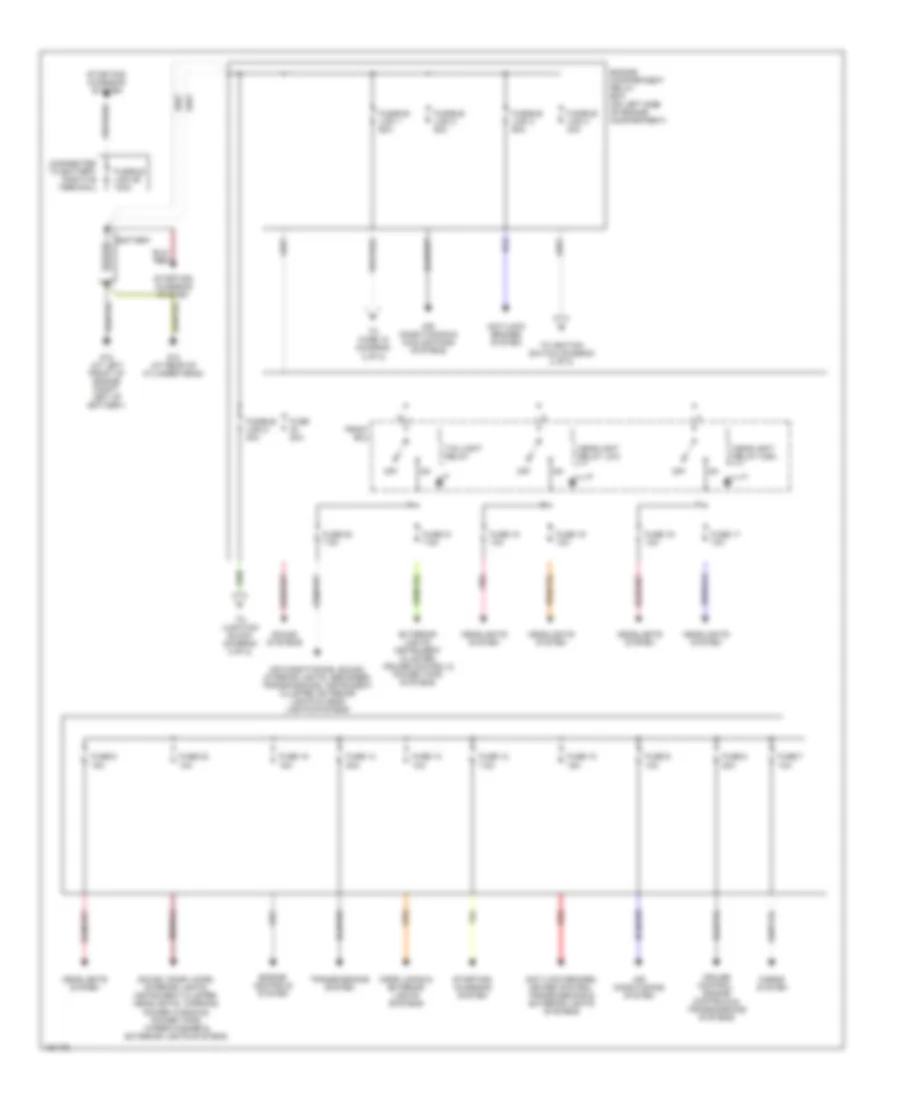
Электросхема блока предохранителей и реле, Универсал (1 из 2) для Mitsubishi Lancer Evolution 2004
Электросхема блока предохранителей и реле, Универсал (1 из 2) для Mitsubishi Lancer Evolution 2004 - Список элементов:
- (connected to battery positive terminal)
- Air conditioning & cooling fans systems
- Air conditioning system
- Air conditioning, sound, interior lights, defogger, transmissions, instrument cluster, exterior lights & headlights systems
- Anti-lock brakes system
- Anti-lock brakes, cruise control, transmissions & exterior lights systems
- Battery
- Cruise control, engine controls, transmissions, cooling fans & air conditioning systems
- Door locks & exterior lights systems
- Engine compartment relay box (on left side of engine compartment)
- Engine controls system
- Exterior lights, cruise control & instrument cluster systems
- Front ecu
- Fuse 10 15a
- Fuse 12 7.5a
- Fuse 13 10a
- Fuse 14 20a
- Fuse 15 15a
- Fuse 16 10a
- Fuse 17 10a
- Fuse 18 10a
- Fuse 19 10a
- Fuse 20 7.5a
- Fuse 21 7.5a
- Fuse 22 10a
- Fuse 6 15a
- Fuse 7 10a
- Fuse 8 20a
- Fuse 9 10a
- Fusible link 1 60a
- Fusible link 2 50a
- Fusible link 26 100a
- Fusible link 3 60a
- Fusible link 4 40a
- Fusible link 5 30a
- G11 (on left side of cylinder head, under throttle cable)
- Headlight relay high
- Headlight relay low
- Headlights system
- Horns system
- Off
- Pnk
- Red
- Sound, door locks, interior lights, instrument cluster, headlights, warning, power windows, wiper/washer & exterior lights systems
- Starting/ charging system
- Starting/charging system
- Taillight relay
- To fuse 11 (diagram 2 of 2)
- To fuse 15 (diagram 2 of 2)
- To ignition switch (diagram 2 of 2)
- To junction block (diagram 2 of 2)
- Transmissions system
Электросхема блока предохранителей и реле, Универсал (2 из 2) для Mitsubishi Lancer Evolution 2004
Электросхема блока предохранителей и реле, Универсал (2 из 2) для Mitsubishi Lancer Evolution 2004 - Список элементов:
- Acc
- Accessory socket
- Accessory socket relay
- Air conditioning system
- Air conditioning, cooling fans, transmissions & engine controls systems
- Air conditioning, wiper/washer, headlights & exterior lights systems
- Anti-lock brakes system
- C210
- C212
- C213
- C215
- Cigarette lighter
- Compartment)
- Cruise control, starting/charging & engine controls systems
- D26
- D27
- Defogger system
- Defogger system
- Engine compartment relay box (on left side of engine
- Engine controls system
- From fuse 12 (diagram 1 of 2)
- From fusible link 1 (diagram 1 of 2)
- From fusible link 4 (diagram 1 of 2)
- From fusible link 5 (diagram 1 of 2)
- Fuse 1 10a
- Fuse 11 15a
- Fuse 11 7.5a
- Fuse 12 7.5a
- Fuse 14 15a
- Fuse 15 15a
- Fuse 19 30a
- Fuse 2 7.5a
- Fuse 20 30a
- Fuse 23 10a
- Fuse 3 7.5a
- Fuse 5 7.5a
- Fuse 7 20a
- Fuse 8 7.5a
- Fuse 9 15a
- G3 (under right front kick panel)
- G7 (at top left side of dash)
- Ignition switch
- Instrument cluster, interior lights & sound systems
- Joint connector 3 (behind right side of dash)
- Junction block (behind left end of dash)
- Lock
- Mirrors system
- Off
- Power windows system
- Red
- Start
- Wiper/washer & interior lights systems
- Wiper/washer system
БЛОКИ УПРАВЛЕНИЯ КУЗОВОМ
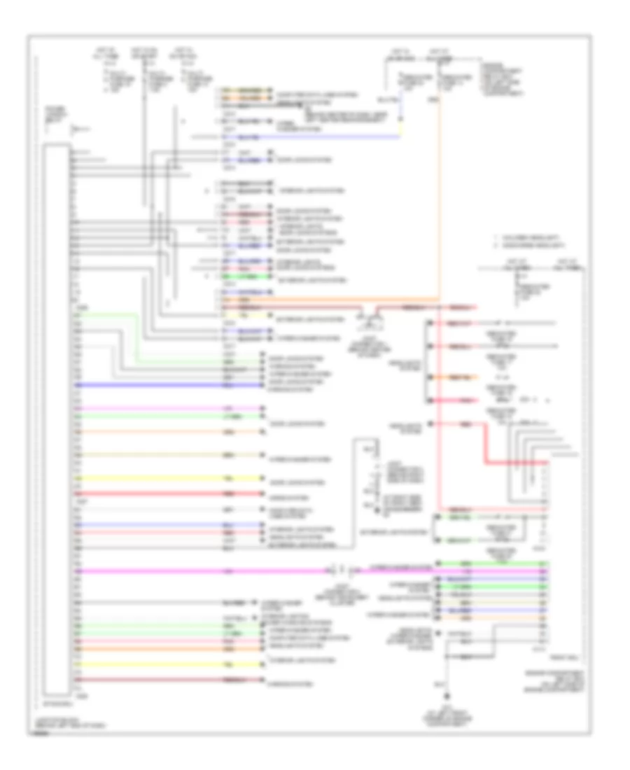
Электросхема блоков управления кузовом, эволюция для Mitsubishi Lancer Evolution 2004
Электросхема блоков управления кузовом, эволюция для Mitsubishi Lancer Evolution 2004 - Список элементов:
- (at right side of front deck crossmember) g3
- (discharge headlight)
- (halogen headlight)
- 10a
- 20a
- A10x
- A11x
- All times
- C210
- C214
- C217
- C218
- C226
- C227
- C228
- Computer data lines system
- Dedicated fuse 13 10a
- Dedicated fuse 16 10a
- Dedicated fuse 17 10a
- Dedicated fuse 18
- Dedicated fuse 19
- Dedicated fuse 20 7.5a
- Dedicated fuse 21 7.5a
- Dedicated fuse 22 10a
- Dedicated fuse 23 10a
- Door locks system
- Engine compartment relay box (on left side of engine compartment)
- Engine compartment relay box (on left side of engine compartment)
- Etacs ecu
- Exterior lights system
- Front ecu
- G13 (at left front corner of engine compartment)
- G6 (behind center of dash, near left center reinforcement)
- Headlights system
- Headlights, wiper/washer, exterior lights systems
- Horns system
- Hot at
- Hot in
- Hot in on
- Interior lights & power windows systems
- Interior lights system
- Interior lights, door locks systems
- Joint connector 1 (behind center of dash)
- Joint connector 2 (behind instrument cluster)
- Joint connector 3 (behind right side of dash)
- Junction block (behind left end of dash)
- Multi- purpose fuse 14 15a
- Multi- purpose fuse 15 15a
- Multi- purpose fuse 2 7.5a
- On or acc
- Or start
- Pnk
- Power window relay
- Red
- Warning system
- Wiper/ washer system
- Wiper/washer system
Электросхема блоков управления кузовом, кроме эволюции для Mitsubishi Lancer Evolution 2004
Электросхема блоков управления кузовом, кроме эволюции для Mitsubishi Lancer Evolution 2004 - Список элементов:
- (at left front (at left front of engine compt, left of battery)
- (on center tunnel, right of accelerator pedal) (wagon) g5
- (sedan) (wagon)
- A10x
- A11x
- All times
- C210
- C211
- C214
- C215
- C217
- C218
- C219
- C226
- C227
- C228
- C229
- Computer data lines system
- Corner of engine compartment)
- Dedicated fuse 13 10a
- Dedicated fuse 16 10a
- Dedicated fuse 17 10a
- Dedicated fuse 18 10a
- Dedicated fuse 19 10a
- Dedicated fuse 20 7.5a
- Dedicated fuse 21 7.5a
- Dedicated fuse 22 10a
- Dedicated fuse 23 10a
- Door locks system
- Engine compartment relay box (on left side of engine compartment)
- Engine compartment relay box (on left side of engine compartment)
- Etacs ecu
- Exterior lights system
- Front ecu
- G13 g12
- G3 (under right front kick panel)
- G6 (sedan) (behind center of dash, near left center reinforcement)
- Headlights system
- Headlights sytem
- Headlights, wiper/washer, exterior lights systems
- Horns system
- Hot at
- Hot in
- Hot in on
- Interior lights system
- Interior lights, door locks systems
- Interior lights, door locks systems
- Joint connector 1 (behind center of dash)
- Joint connector 2 (behind instrument cluster)
- Junction block (behind left end of dash)
- Multi- purpose fuse 14 15a
- Multi- purpose fuse 15 15a
- Multi- purpose fuse 2 7.5a
- On or acc
- Or start
- Pnk
- Power tops system
- Power window relay
- Red
- Sedan
- Wagon
- Warning system
- Wiper/washer system
ВНЕШНЕЕ ОСВЕЩЕНИЕ
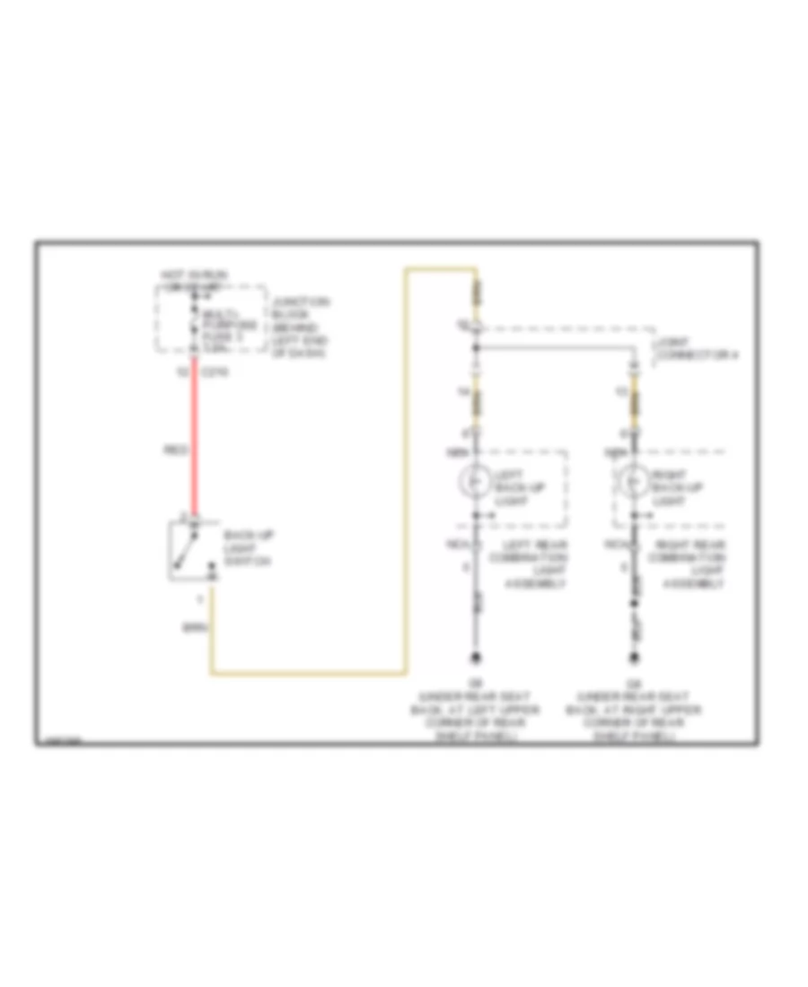
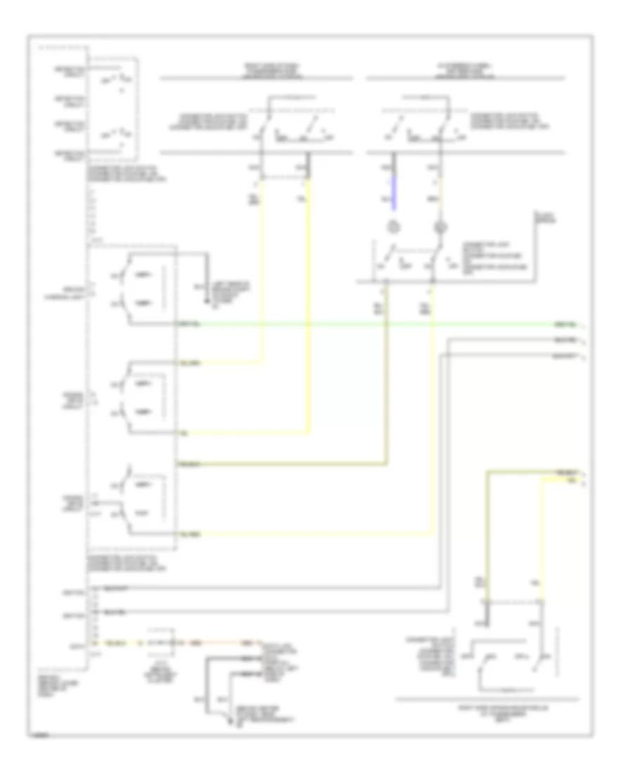
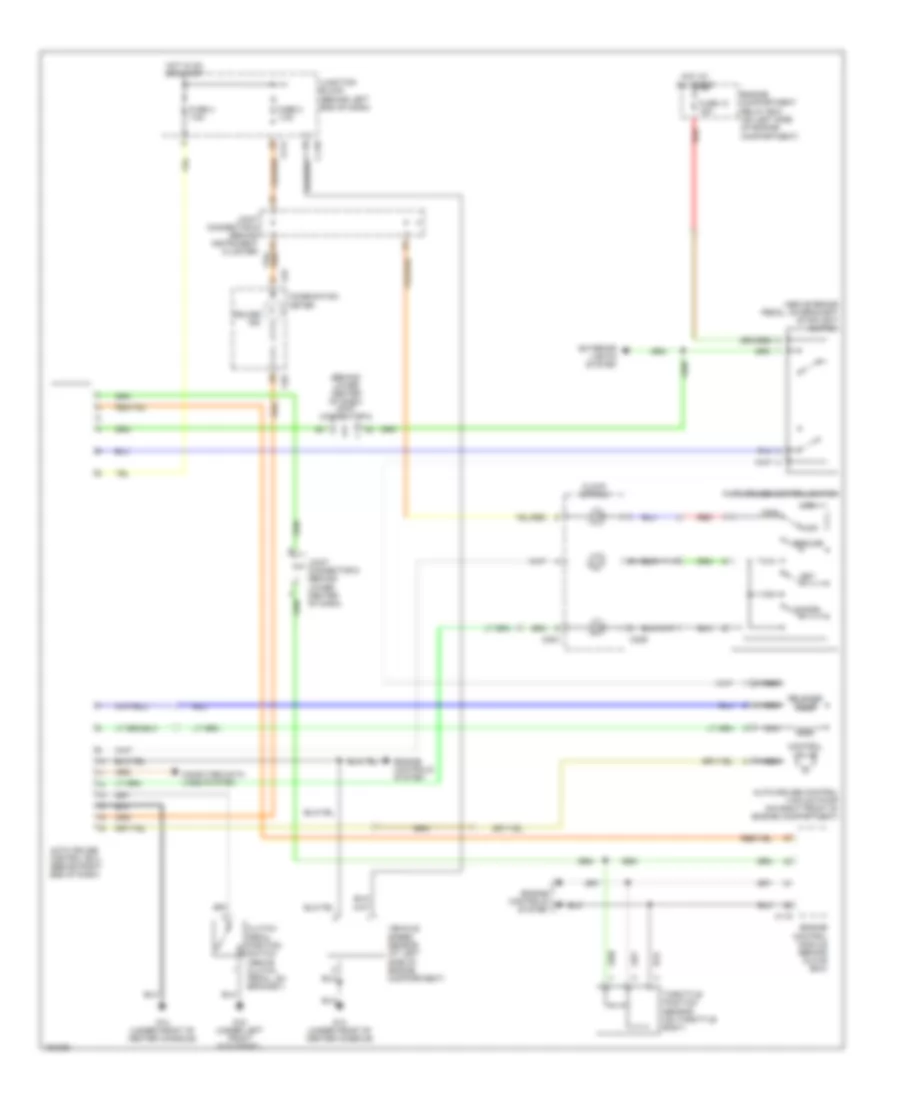
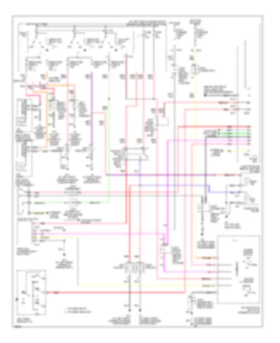
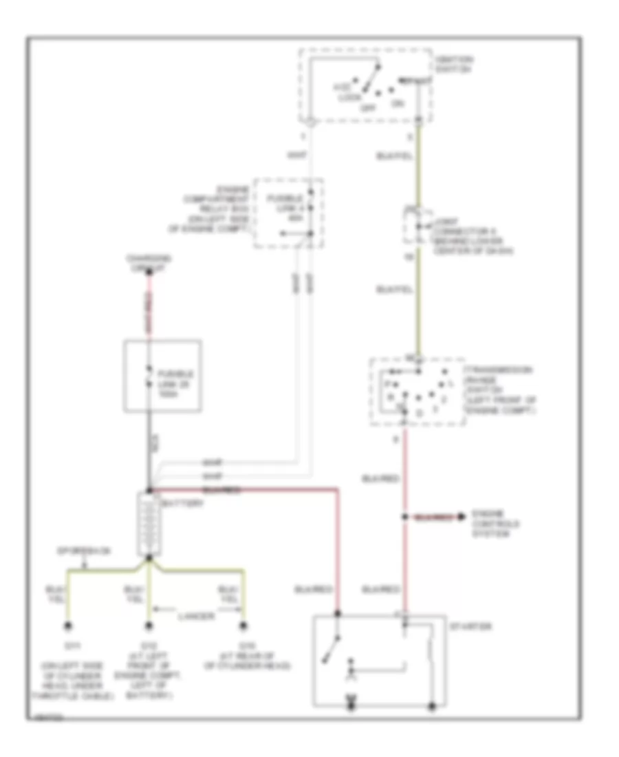
Электросхема заднего хода, эволюция для Mitsubishi Lancer Evolution 2004
Электросхема заднего хода, эволюция для Mitsubishi Lancer Evolution 2004 - Список элементов:
- Back-up light switch
- C210
- G8 (under rear seat back, at right upper corner of rear shelf panel)
- G9 (under rear seat back, at left upper corner of rear shelf panel)
- Hot in run or start
- Joint connector 4
- Junction block (behind left end of dash)
- Left back-up light
- Left rear combination light assembly
- Multi- purpose fuse 3 7.5a
- Nca
- Red
- Right back-up light
- Right rear combination light assembly
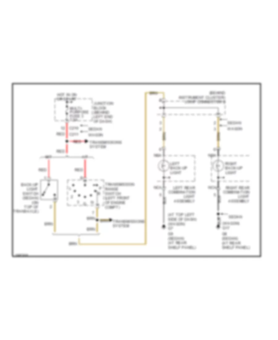
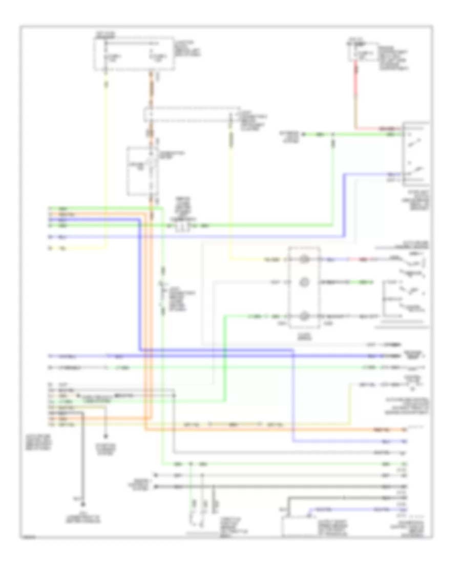
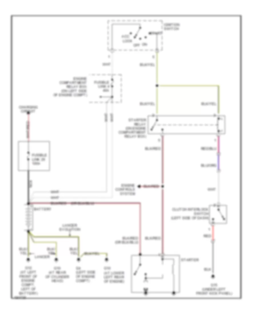
Электросхема заднего хода, кроме эволюции для Mitsubishi Lancer Evolution 2004
Электросхема заднего хода, кроме эволюции для Mitsubishi Lancer Evolution 2004 - Список элементов:
- (at top left side of dash) (wagon) g7
- (behind instrument cluster) joint connector 2
- (wagon) g17
- A/t
- Back-up light switch (sedan) (on top of transaxle)
- C210
- G8 (sedan) (at rear shelf panel)
- G9 (sedan) (at rear shelf panel)
- Hot in on or start
- Junction block (behind left end of dash)
- Left back-up light
- Left rear combination light assembly
- M/t
- Multi- purpose fuse 3 7.5a
- Nca
- Red
- Red c211
- Right back-up light
- Right rear combination light assembly
- Sedan
- Transmission range switch (left front of engine compt)
- Transmissions system
- Wagon
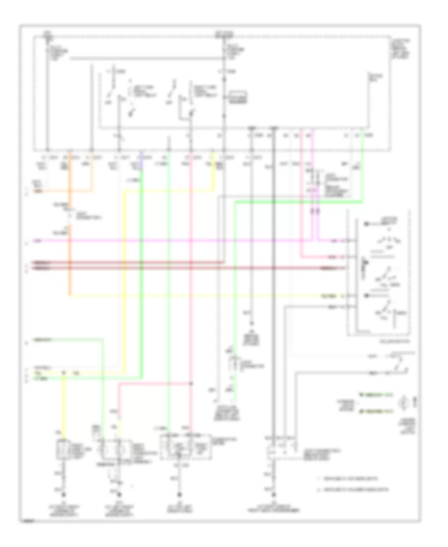
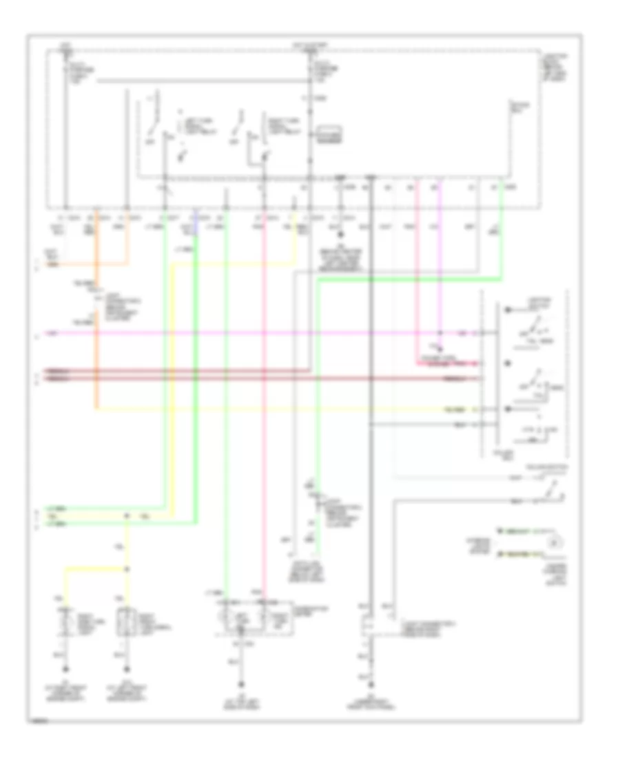
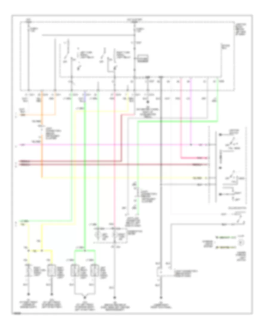
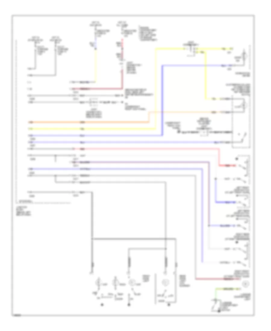
Электросхема внешнего освещения, эволюция (1 из 2) для Mitsubishi Lancer Evolution 2004
Электросхема внешнего освещения, эволюция (1 из 2) для Mitsubishi Lancer Evolution 2004 - Список элементов:
- (not used)
- A10x
- A11x
- Air conditioning system
- Anti-lock brakes system
- Anti-theft system
- Back-up lamps circuit
- C210
- C217
- Dedicated fuse 10 15a
- Dedicated fuse 13 10a
- Dedicated fuse 20 7.5a
- Dedicated fuse 21 7.5a
- Dedicated fuse 22 10a
- Engine compartment relay box (on left side of engine compartment)
- Front ecu
- G1 (at right front corner of engine compartment)
- G13 (at left front corner of engine compartment)
- G8 (under rear seat back, at right upper corner of rear shelf panel)
- G9 (under rear seat back, at left upper corner of rear shelf panel)
- Gnd
- Headlights system
- High mounted stop light
- Hot at all times
- Joint connector 1 (behind center of dash)
- Joint connector 2 (behind instrument cluster)
- Junction block (behind left end of dash)
- Left front combi- nation assembly
- Left license plate light
- Left rear combination light assembly turn
- Left rear side marker light
- Left side turn signal light
- Nca
- Off
- Position
- Power source
- Red
- Right license plate light
- Right rear combination light assembly turn
- Right rear side marker light
- Stop
- Stoplight switch (above brake pedal, on bracket)
- Tail
- Taillight relay
- Turn
- Vehicles w/ halogen headlights
- Vehicles w/ hid headlights
Электросхема внешнего освещения, эволюция (2 из 2) для Mitsubishi Lancer Evolution 2004
Электросхема внешнего освещения, эволюция (2 из 2) для Mitsubishi Lancer Evolution 2004 - Список элементов:
- C01
- C02
- C210
- C214
- C217
- C226
- C228
- Column switch
- Column-ecu
- Combination meter
- Data link connector (below left side of dash)
- Etacs ecu
- G1 (at right front corner of engine compt)
- G13 (at left front corner of engine compt)
- G3 (at right side of front deck crossmember)
- G6 (behind center of dash)
- G7 (at top left side of dash)
- Gnd
- Hazard warning light switch
- Head
- Hot in on
- Hot in on or start
- Illum
- Interior lights system
- Joint connector
- Joint connector (behind instrument cluster)
- Joint connector 3 (behind right side of dash)
- Joint connector 4
- Junction block (behind left end of dash)
- Left turn ind
- Left turn signal light relay
- Lighting switch
- Multi- purpose fuse 2 7.5a
- Multi- purpose fuse 5 7.5a
- Off
- Pnk
- Position
- Power source
- Right front combination light assembly
- Right side turn signal light
- Right turn ind
- Right turn signal light relay
- Tail
- Turn
- Vehicles w/ halogen headlights
- Vehicles w/ hid headlights
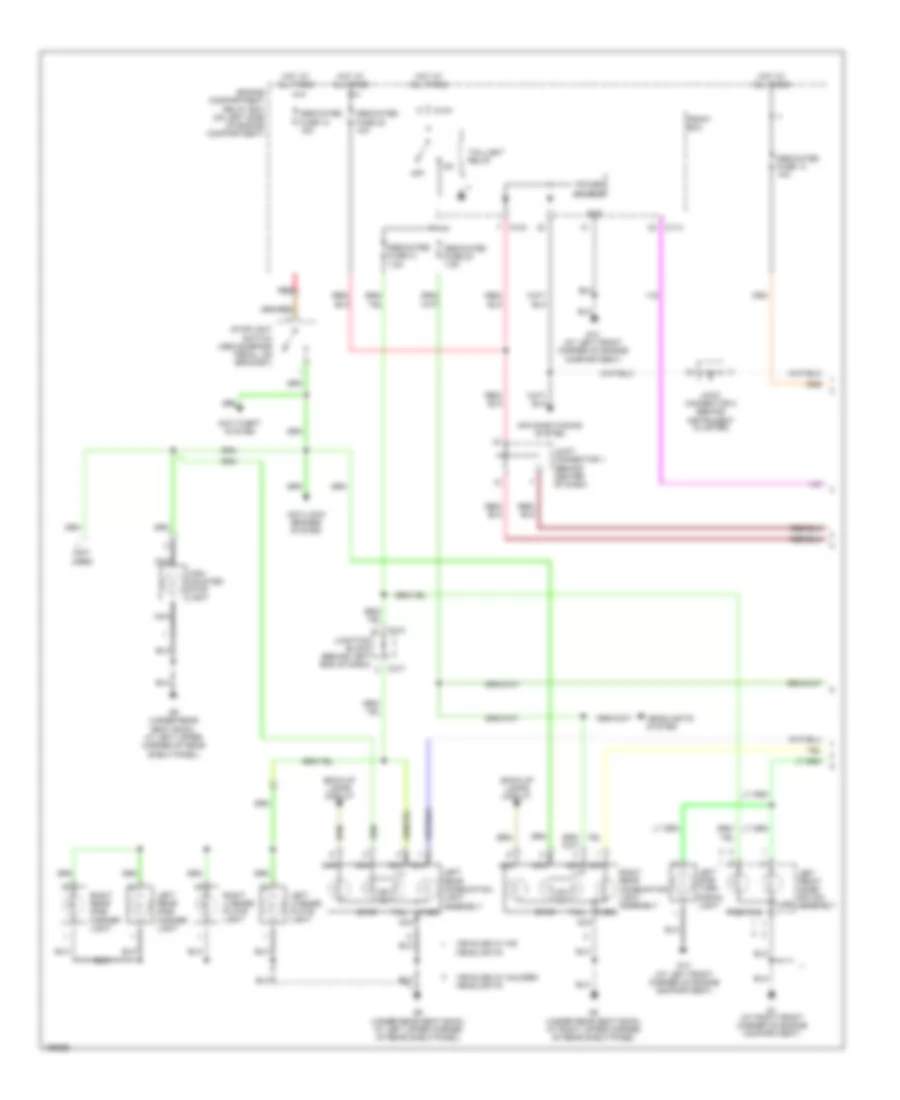
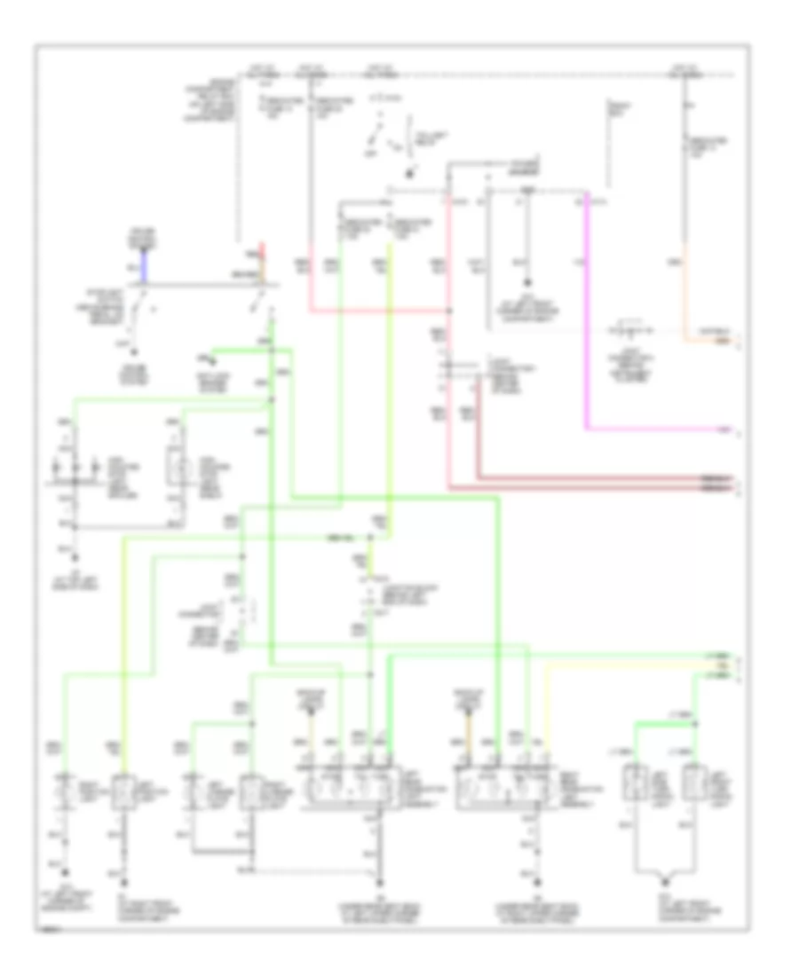
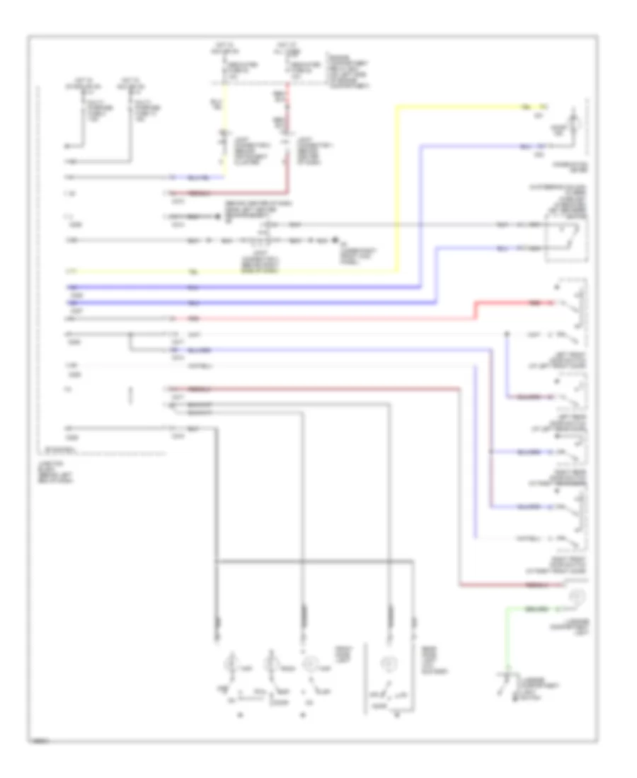
Электросхема внешнего освещения, кроме Универсала или эволюции (1 из 2) для Mitsubishi Lancer Evolution 2004
Электросхема внешнего освещения, кроме Универсала или эволюции (1 из 2) для Mitsubishi Lancer Evolution 2004 - Список элементов:
- A10x
- A11x
- Anti-lock brakes system
- Back-up lamps circuit
- C210
- C217
- Cruise control system
- Dedicated fuse 10 15a
- Dedicated fuse 13 10a
- Dedicated fuse 20 7.5a
- Dedicated fuse 21 7.5a
- Dedicated fuse 22 10a
- Engine compartment relay box (on left side of engine compartment)
- Front ecu
- G1 (at right front corner of engine compartment)
- G13 (at left front corner of engine compartment)
- G13 (at left front corner of engine compt)
- G7 (at top left side of dash)
- G8 (under rear seat back, at right upper corner of rear shelf panel)
- G9 (under rear seat back, at left upper corner of rear shelf panel)
- Gnd
- High mounted stop light (rear shelf)
- High mounted stop light (rear spoiler)
- Hot at all times
- Joint connector (behind center of dash)
- Joint connector 1 (behind center of dash)
- Joint connector 2 (behind instrument cluster)
- Junction block (behind left end of dash)
- Left front turn signal light
- Left license plate light
- Left position light
- Left rear combination light assembly
- Left side turn signal light
- Nca
- Off
- Power source
- Red
- Right license plate light
- Right position light
- Right rear combination light assembly
- Stop
- Stoplight switch (above brake pedal, on bracket)
- Tail
- Taillight relay
- Turn
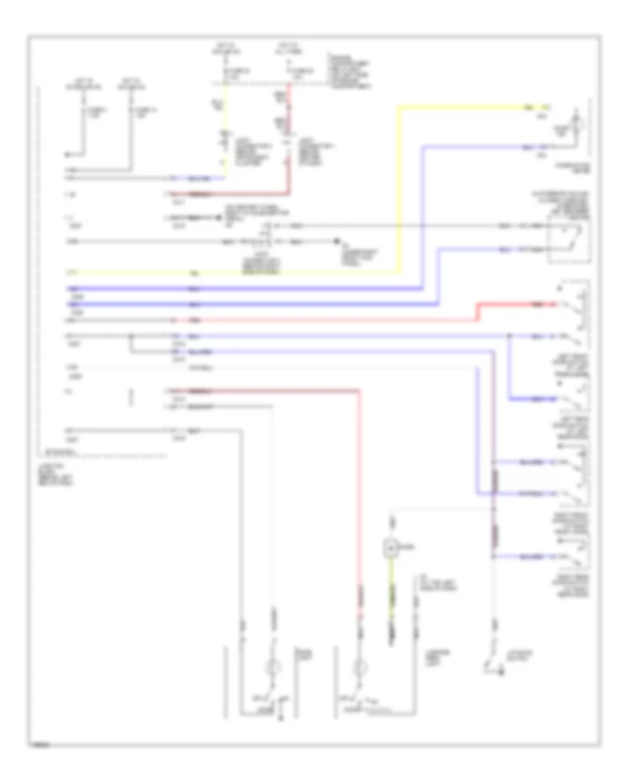
Электросхема внешнего освещения, кроме Универсала или эволюции (2 из 2) для Mitsubishi Lancer Evolution 2004
Электросхема внешнего освещения, кроме Универсала или эволюции (2 из 2) для Mitsubishi Lancer Evolution 2004 - Список элементов:
- C01
- C02
- C210
- C214
- C217
- C226
- C228
- Column ecu
- Column switch
- Combination meter
- Data link connector (below left side of dash)
- Etacs ecu
- G1 (at right front corner of engine compt)
- G13 (at left front corner of engine compt)
- G3 (under right front kick panel)
- G6 (behind center of dash, near left center reinforcement)
- G7 (at top left side of dash)
- Gnd
- Hazard warning light switch
- Head
- Hot in on
- Hot in start or on
- Interior lights system
- Joint connector 2 (behind instrument cluster)
- Joint connector 3 (behind right side of dash)
- Joint connector 5 (behind instrument cluster)
- Junction block (behind left end of dash)
- Left turn ind
- Left turn signal light relay
- Lighting switch
- Multi- purpose fuse 2 7.5a
- Multi- purpose fuse 5 7.5a
- Off
- Pnk
- Power source
- Power tops system
- Right front turn signal light
- Right side turn signal light
- Right turn ind
- Right turn signal light relay
- Tail
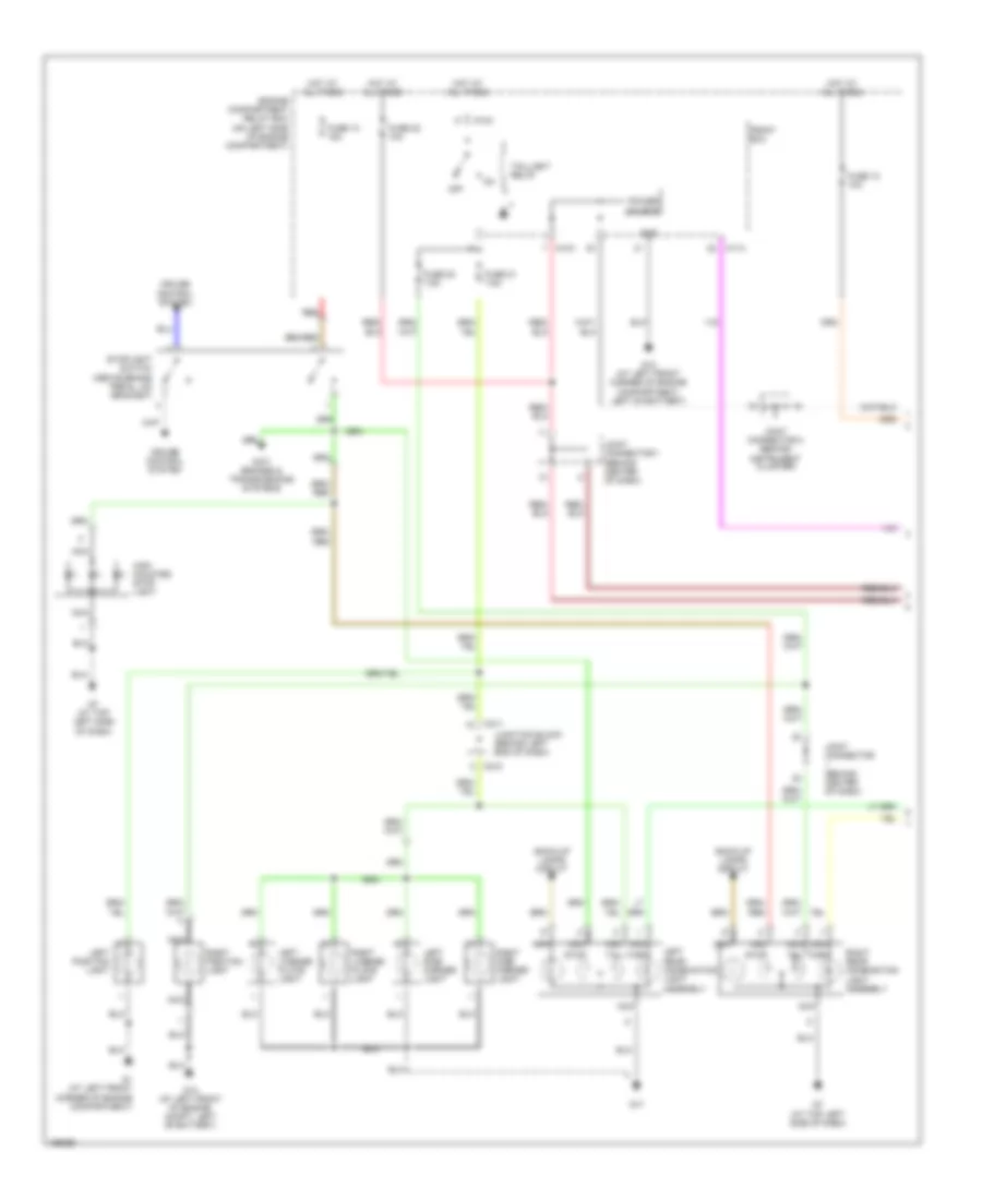
Электросхема внешнего освещения, Универсал (1 из 2) для Mitsubishi Lancer Evolution 2004
Электросхема внешнего освещения, Универсал (1 из 2) для Mitsubishi Lancer Evolution 2004 - Список элементов:
- A10x
- A11x
- Anti brakes & transmissions systems
- Back-up lamps circuit
- C211
- C218
- Cruise control system
- Engine compartment relay box (on left side of engine compartment)
- Front ecu
- Fuse 10 15a
- Fuse 13 10a
- Fuse 20 7.5a
- Fuse 21 7.5a
- Fuse 22 10a
- G1 (at left front corner of engine compartment)
- G12 (at left front corner of engine compartment, left of battery)
- G12 (at left front of engine compt, left of battery)
- G17
- G7 (at top left side of dash)
- Gnd
- High mounted stop light
- Hot at all times
- Joint connector (behind center of dash)
- Joint connector 1 (behind center of dash)
- Joint connector 2 (behind instrument cluster)
- Junction block (behind left end of dash)
- Left license plate light
- Left position light
- Left rear combination light assembly
- Left side marker light
- Nca
- Off
- Power source
- Red
- Right license plate light
- Right position light
- Right rear combination light assembly
- Right side marker light
- Stop
- Stoplight switch (above brake pedal, on bracket)
- Tail
- Taillight relay
- Turn
Электросхема внешнего освещения, Универсал (2 из 2) для Mitsubishi Lancer Evolution 2004
Электросхема внешнего освещения, Универсал (2 из 2) для Mitsubishi Lancer Evolution 2004 - Список элементов:
- C02
- C04
- C211
- C215
- C218
- C227
- C229
- Column ecu
- Column switch
- Combination meter
- Data link connector (below left side of dash)
- Etacs ecu
- Fuse 2 7.5a
- Fuse 5 7.5a
- G1 (at right front corner of engine compt)
- G12 (at left front of engine compt, left of battery)
- G3 (under right front kick panel)
- G5 (on center tunnel, right of accelerator pedal)
- G6 (behind center of dash, near left center reinforcement)
- Gnd
- Hazard warning light switch
- Head
- Hot in on
- Hot in start or on
- Illum
- Interior lights system
- Joint connector 2 (behind instrument cluster)
- Joint connector 3 (behind right side of dash)
- Joint connector 5 (behind instrument cluster)
- Junction block (behind left end of dash)
- Left
- Left front turn signal light
- Left side turn signal light
- Left turn ind
- Left turn signal light relay
- Lighting switch
- Off
- Pnk
- Power source
- Right
- Right front turn signal light
- Right side turn signal light
- Right turn ind
- Right turn signal light relay
- Tail
ВНУТРЕННЕЕ ОСВЕЩЕНИЕ
Электросхема подсветки, эволюция для Mitsubishi Lancer Evolution 2004
Электросхема подсветки, эволюция для Mitsubishi Lancer Evolution 2004 - Список элементов:
- (behind center of dash, near left center reinforcement)
- (behind instrument cluster)
- (in steering column) (closed when key is removed) key reminder switch
- (under right front kick panel) g3
- 10a
- C01
- C02
- C210
- C214
- C217
- C218
- C226
- C227
- C228
- Combination meter
- Dedicated fuse 22
- Dedicated fuse 23
- Door
- Engine compartment relay box (on left side of engine compartment)
- Etacs ecu
- Front dome light
- G3 (under right front kick panel)
- Hot at all times
- Hot in acc or on
- Hot in start or on
- Illum
- Ind
- Joint connector 1 (behind center of dash)
- Joint connector 2
- Joint connector 3 (behind right side of dash)
- Joint connector 4
- Junction block (behind left end of dash)
- Left front door switch (at left front door)
- Left rear door switch (at left rear door)
- Luggage compartment light
- Luggage compartment light switch
- Map
- Multi- purpose fuse 14 15a
- Multi- purpose fuse 2 7.5a
- Nca
- Off
- Rear dome light (w/o sunroof)
- Red
- Right front door switch (at right front door)
- Right rear door switch (at right rear door)
- Room
Электросхема подсветки, кроме Универсала или эволюции для Mitsubishi Lancer Evolution 2004
Электросхема подсветки, кроме Универсала или эволюции для Mitsubishi Lancer Evolution 2004 - Список элементов:
- (behind center of dash, near left center reinforcement) g6
- (in steering column) (closed when key is removed) key reminder switch
- 10a
- C01
- C02
- C210
- C214
- C217
- C218
- C226
- C227
- C228
- Combination meter
- Dedicated fuse 22
- Dedicated fuse 23
- Door
- Door ind
- Engine compartment relay box (on left side of engine compartment)
- Etacs ecu
- Front dome light
- G3 (under right front kick panel)
- Hot at all times
- Hot in acc or on
- Hot in start or on
- Joint connector 1 (behind center of dash)
- Joint connector 2 (behind instrument cluster)
- Joint connector 3 (behind right side of dash)
- Junction block (behind left end of dash)
- Left front door switch (at left front door)
- Left rear door switch (at left rear door)
- Luggage compartment light
- Luggage compartment light switch
- Map
- Multi- purpose fuse 14 15a
- Multi- purpose fuse 2 7.5a
- Nca
- Off
- Rear dome light (w/o sun roof)
- Red
- Right front door switch (at right front door)
- Right rear door switch (at right rear door)
- Room
Электросхема подсветки, Универсал для Mitsubishi Lancer Evolution 2004
Электросхема подсветки, Универсал для Mitsubishi Lancer Evolution 2004 - Список элементов:
- (in steering column) (closed when key is removed) key reminder switch
- (on center tunnel, right of accelerator pedal) g5
- 10a
- C02
- C04
- C211
- C215
- C218
- C219
- C227
- C228
- C229
- Combination meter
- Diode
- Dome light
- Door
- Door ind
- Engine compartment relay box (on left side of engine compartment)
- Etacs ecu
- Fuse 14 15a
- Fuse 2 7.5a
- Fuse 22
- Fuse 23
- G3 (under right front kick panel)
- G7 (at top left side of dash)
- Hot at all times
- Hot in acc or on
- Hot in start or on
- Joint connector 1 (behind center of dash)
- Joint connector 2 (behind instrument cluster)
- Joint connector 3 (behind right side of dash)
- Junction block (behind left end of dash)
- Left front door switch (at left front door)
- Left rear door switch (at left rear door)
- Liftgate switch
- Luggage area light
- Nca
- Off
- Red
- Right front door switch (at right front door)
- Right rear door switch (at right rear door)
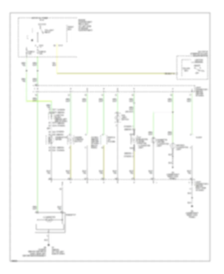
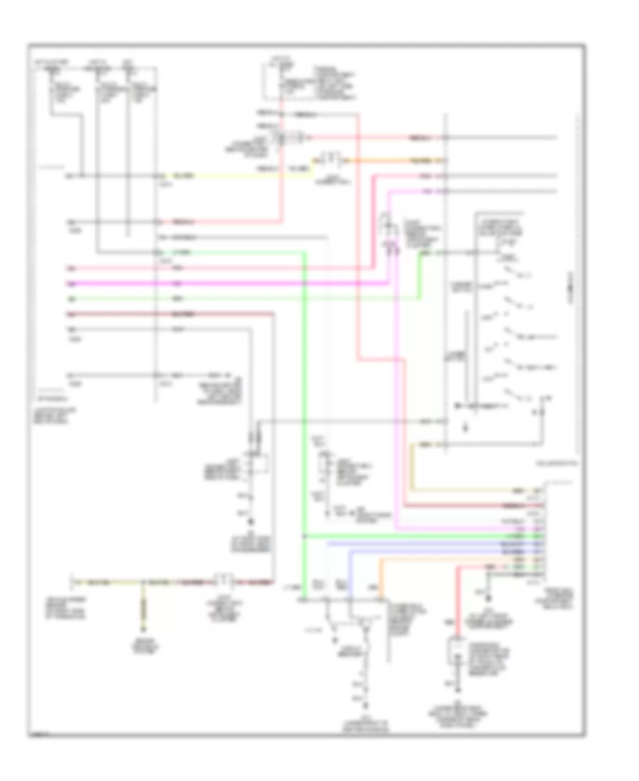
Электросхема подсветки приборов, эволюция для Mitsubishi Lancer Evolution 2004
Электросхема подсветки приборов, эволюция для Mitsubishi Lancer Evolution 2004 - Список элементов:
- (on top of steering column) column switch
- 5 bulbs
- A/c ecu (behind center of dash)
- A10x
- A11x
- Ashtray illumination light
- C02
- C210
- C214
- Charge air cooler water spray switch
- Cigarette lighter illumination light
- Clock
- Column ecu
- Combination meter
- Engine compartment relay box (at left side of engine compartment)
- Fog light switch
- Front ecu
- Fuse 20 7.5a
- Fuse 21 7.5a
- G3 (under right front kick panel)
- G7 (at top left side of dash)
- Hazard warning light switch
- Head
- Hot at all times
- Illumination
- Joint connector 1 (behind center of dash)
- Joint connector 3 (behind right side of dash)
- Junction block (behind left end of dash)
- Lighting switch
- Off
- Radio & cd player
- Rheostat
- Tail
- Taillight relay
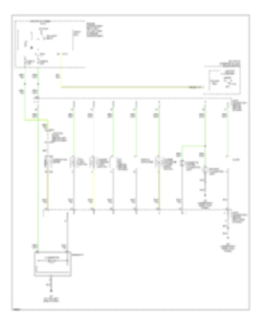
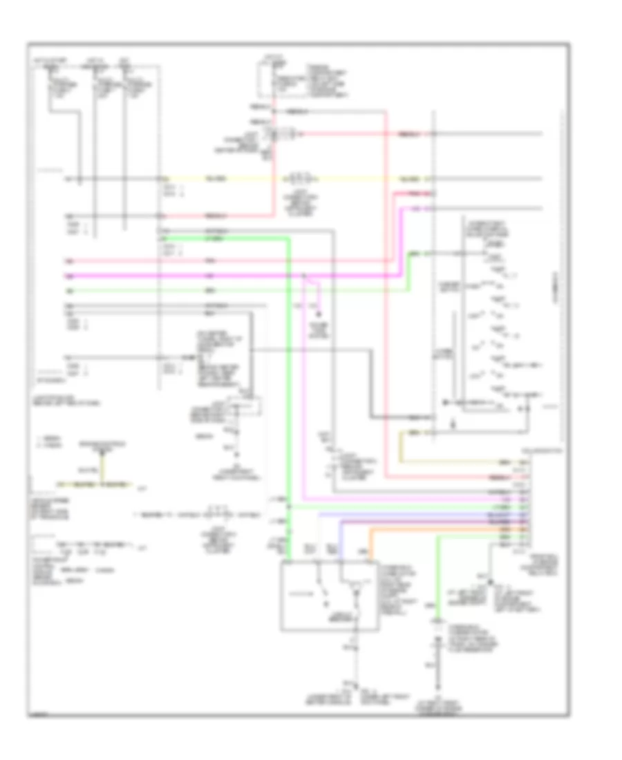
Электросхема подсветки приборов, кроме эволюции для Mitsubishi Lancer Evolution 2004
Электросхема подсветки приборов, кроме эволюции для Mitsubishi Lancer Evolution 2004 - Список элементов:
- (on top of steering column) column switch
- (sedan)
- (sedan) (at top left side of dash)
- (wagon)
- 5 bulbs
- A/c ecu (behind center of dash, below radio)
- A/t selector lever position illumination light
- A10x
- A11x
- Ashtray illumination light
- C02
- C04
- C210
- C211
- C214
- C215
- Cigarette lighter illumination light
- Clock
- Column ecu
- Combination meter
- Engine compartment relay box (at left side of engine compartment)
- Fog light switch
- Front ecu
- Fuse 20 7.5a
- Fuse 21 7.5a
- G3 (under right front kick panel)
- G6 (wagon) (behind center of dash, near left center reinforcement)
- Hazard warning switch
- Head
- Hot at all times
- Illumination
- Joint connector 1 (behind center of dash)
- Joint connector 3 (behind right side of dash)
- Junction block (behind left end of dash)
- Lighting switch
- Nca
- Off
- Radio & cd player
- Rheostat
- Tail
- Taillight relay
ЗАЗЕМЛЕНИЕ ПОДКЛЮЧЕНИЕ МАССЫ
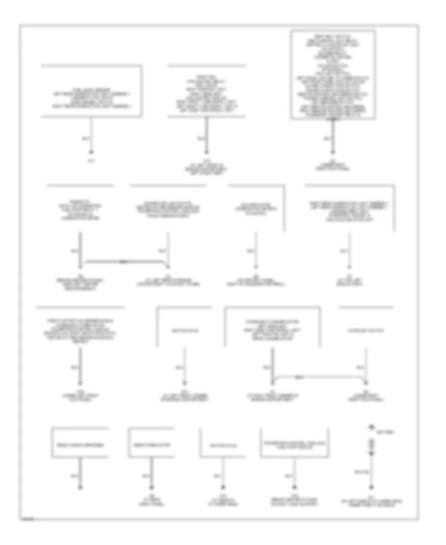
Электросхема подключение массы заземления, эволюция для Mitsubishi Lancer Evolution 2004
Электросхема подключение массы заземления, эволюция для Mitsubishi Lancer Evolution 2004 - Список элементов:
- Battery
- Clutch interlock switch & clutch pedal position switch
- Combination meter, audio amplifier & connector lock switch
- Fuel pump relay 1, etacs ecu, charge air cooler water spray switch, combination meter & blower motor
- G1 (at right front corner of engine compartment)
- G10 (at lower left rear of engine)
- G11 (at rear of engine, below cylinder head)
- G13 (at left front corner of engine compartment)
- G14 (under front of center console)
- G15 (under left front kick panel)
- G16 (behind center of dash, on right dash support)
- G17 (at sunroof motor assembly)
- G2 (at right "a" pillar)
- G3 (at right side of front deck crossmember)
- G4 (left side of engine compartment)
- G5 (on center tunnel, right of accelerator pedal)
- G6 (behind center of dash, near left center reinforcement)
- G7 (at top left side of dash)
- G8 (under rear seat back, at right upper corner of rear shelf panel)
- G9 (under rear seat back, at left upper corner of rear shelf panel)
- Hazard warning light switch, rheostat, immobilizer ecu, steering angular velocity sensor, cigarette lighter, heater control (a/c ecu), blower relay, seat belt switch, column ecu, etacs ecu, data link connector, combination meter, fog light switch, clock, column switch, key reminder switch & ashtray illumination light
- Heater control (a/c ecu), seat belt switch, blower relay, cigarette lighter, clock, column switch, etacs ecu, fog light switch, key reminder switch, left door lock key cylinder switch, left front door lock actuator, power window main switch, power window sub switch, remote controlled mirror switch, steering angular velocity sensor, immobilizer-ecu, hazard warning light switch & ashtray illumination light
- Ignition coils
- Knock sensor shield, vehicle speed sensor, ignition coils, heated oxygen sensor shields & engine control module
- Left front combination light assembly, right front combination light assembly, left headlight (high), right side turn signal light & right fog light
- Left front combination light assembly, right headlight, left fog light, condenser fan motor, fan control module, fan control relay, front ecu, left side turn signal light, right front combination light assembly & charge air cooler water spray motor
- License plate lights, left rear combination light assembly,
- Main fuel pump & level sensor, fuel temperature sensor & right side turn signal light
- Rear washer motor, right rear combination light assembly & windshield washer motor
- Rear window defogger
- Rear wiper motor, rear side marker lights & high mounted stoplight
- Sunroof motor assembly & sunroof switch
- Windshield wiper motor, abs ecu, engine control module, heated oxygen sensor shields, vehicle speed sensor & brake fluid level indicator switch
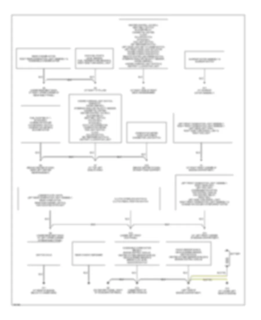
Электросхема подключение массы заземления, кроме Универсала или эволюции для Mitsubishi Lancer Evolution 2004
Электросхема подключение массы заземления, кроме Универсала или эволюции для Mitsubishi Lancer Evolution 2004 - Список элементов:
- 2.4l
- Abs ecu, auto-cruise control ecu (2.0l), throttle position sensor shield, engine control module, heated oxygen sensor shields, powertrain control module, vehicle speed sensor & windshield wiper motor
- Battery
- Connector lock switch
- Data link connector, combination meter, rheostat, rear shelf high mounted stoplight, rear spoiler high mounted stoplight & etacs ecu
- Engine control module (2.4l m/t), brake fluid level indicator switch, clutch pedal position switch, starter relay interlock switch, powertrain control module & throttle position sensor shield
- Etacs ecu
- Fuel level sensor, fuel pump module, license plate lights, left rear combination light assembly,
- Fuel pump relay 1, etacs ecu, audio amplifier, blower motor
- G1 (at right front corner of engine compartment)
- G10 (at rear of cylinder head)
- G11 (on left side of cylinder head, under throttle cable)
- G12 (at left front of engine compartment, left of battery)
- G13 (at left front corner of engine compartment)
- G14 (under front of center console)
- G15 (under left front kick panel)
- G16 (behind center of dash, on right dash support)
- G2 (under right front kick panel)
- G3 (under right front kick panel)
- G4 (at left rear of engine compartment, on shock tower)
- G5 (on center tunnel, right of accelerator pedal)
- G6 (behind center of dash, near left center reinforcement)
- G7 (at top left side of dash)
- G8 (at rear shelf panel)
- G9 (at rear shelf panel)
- Ignition coils
- Ignition coils, heater oxygen sensor shields, powertrain control module, knock sensor shield, engine control module
- Left headlight, left position light, right side turn signal light, windshield washer motor & rear washer motor
- Rear window defogger
- Rear wiper motor
- Right front turn signal light, right headlight, fog lights, fan control module, fan control relay, front ecu, left side turn signal light, left front turn signal light & right position light
- Right rear combination light assembly, sunroof motor assembly, sunroof switch
- Seat belt switch, heater control unit (a/c ecu), abs warning light relay, blower relay, cigarette lighter, clock, column ecu, column switch, etacs ecu, fog light switch, key reminder switch, left door lock key cylinder switch, ashtray illumination light, left front door lock actuator, power window main switch, power window sub switch, remote controlled mirror switch, right door lock key cylinder switch, left remote controlled mirror, right remote controlled mirror, hazard warning light switch
- Stoplight switch
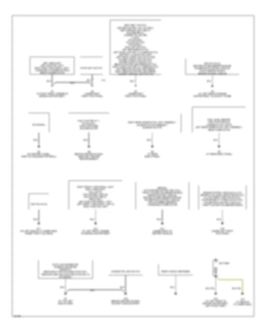
Электросхема подключение массы заземления, Универсал для Mitsubishi Lancer Evolution 2004
Электросхема подключение массы заземления, Универсал для Mitsubishi Lancer Evolution 2004 - Список элементов:
- Battery
- Blower motor, combination meter & etacs ecu
- Connector lock switch, heated oxygen sensor shields, powertrain control module & knock sensor shield
- Front ecu, fan control relay, fog lights, right position light, right headlight, fan control module, right front turn signal light, left front turn signal light & left side turn signal light
- Fuel level sensor, left rear combination light assembly, license plate lights, side marker lights & right rear combination light assembly
- G1 (at right front corner of engine compartment)
- G10 (at rear of cylinder head)
- G11 (on left side of cylinder head, under throttle cable)
- G12 (at left front of engine compartment, left of battery)
- G13 (at left front corner of engine compartment)
- G15 (under left front kick panel)
- G16 (behind center of dash, on right dash support)
- G17
- G2 (under right front kick panel)
- G3 (under right front kick panel)
- G4 (at left rear of engine compartment, on shock tower)
- G5 (on center tunnel, right of accelerator pedal)
- G6 (behind center of dash, near left center reinforcement)
- G7 (at top left side of dash)
- G8 (at rear shelf panel)
- Ignition coils
- Powertrain control module & fuel pump module
- Rear window defogger
- Rear wiper motor
- Rheostat, data link connector, fuel pump relay 1, etacs ecu & combination meter
- Right rear combination light assembly, left rear combination light assembly, luggage area light, accessory socket & high mounted stoplight
- Seat belt switch, abs warning light relay, ashtray illumination light, column ecu, blower relay, cigarette lighter, clock, column switch, etacs ecu, fog light switch, left door lock key cylinder switch, left front door lock actuator, power window main switch, power window sub switch, remote controlled mirror switch, hazard warning light switch, key reminder switch, left remote controlled mirror, right remote controlled mirror, accessory socket relay & a/c-ecu
- Stoplight switch
- Throttle position sensor shield, windshield wiper motor, powertrain control module, brake fluid level indicator switch, heated oxygen sensor shields & abs ecu
- Windshield washer motor, left headlight, right side turn signal light, left position light & rear washer motor
Звуковой сигнал Гудок
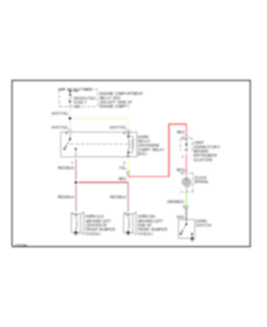
Электросхема звукового сигнал Гудка, эволюция для Mitsubishi Lancer Evolution 2004
Электросхема звукового сигнал Гудка, эволюция для Mitsubishi Lancer Evolution 2004 - Список элементов:
- (behind left center of front bumper fascia)
- (behind left end of front bumper fascia)
- Clock spring
- Dedicated fuse 7 10a
- Engine compartment relay box (on left side of engine compt)
- Horn (hi)
- Horn (lo)
- Horn relay (on engine compt relay box)
- Horn switch
- Hot at all times
- Joint connector 5 (behind instrument cluster)
- Nca
- Red
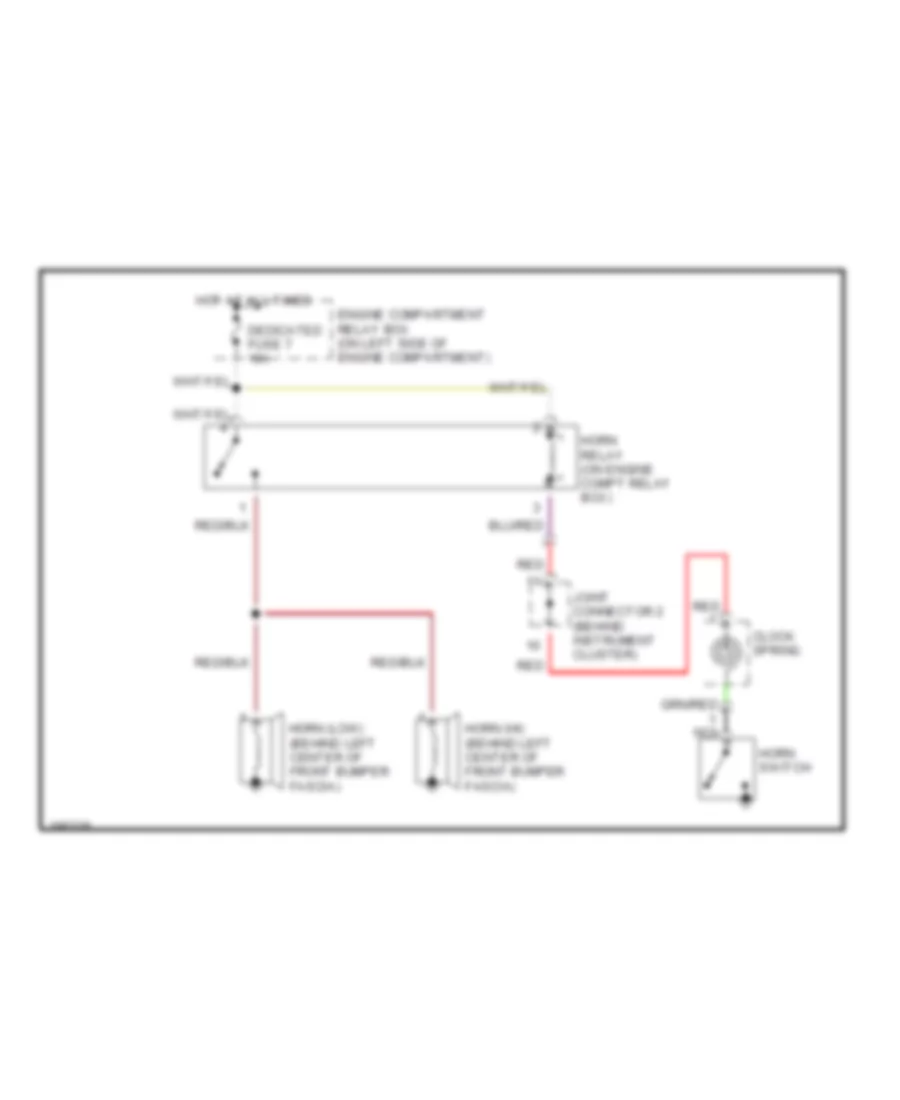
Электросхема звукового сигнал Гудка, кроме эволюции для Mitsubishi Lancer Evolution 2004
Электросхема звукового сигнал Гудка, кроме эволюции для Mitsubishi Lancer Evolution 2004 - Список элементов:
- Clock spring
- Dedicated fuse 7 10a
- Engine compartment relay box (on left side of engine compartment)
- Horn (hi) (behind left center of front bumper fascia)
- Horn (low) (behind left center of front bumper fascia)
- Horn relay (on engine compt relay box)
- Horn switch
- Hot at all times
- Joint connector 2 (behind instrument cluster)
- Nca
- Red
Магнитола Мультимедия
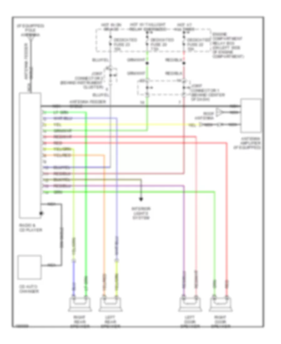
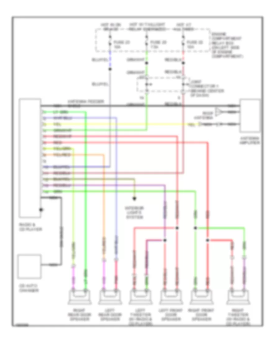
схема с 4 акустическими системами для Mitsubishi Lancer Evolution 2004
схема с 4 акустическими системами для Mitsubishi Lancer Evolution 2004 - Список элементов:
- (if equipped) pole antenna
- Antenna amplifier (if equipped)
- Antenna feeder
- Antenna feeder cable
- Cable nca
- Cd auto changer
- Dedicated fuse 20 7.5a
- Dedicated fuse 22 10a
- Dedicated fuse 23 10a
- Din cable
- Engine compartment relay box (on left side of engine compartment)
- Hot at all times
- Hot in on or acc
- Hot w/ taillight relay energized
- Interior lights system
- Joint connector 1 (behind center of dash)
- Joint connector 2 (behind instrument cluster)
- Left door speaker
- Left rear speaker
- Nca
- Radio & cd player
- Red
- Right door speaker
- Right rear speaker
- Roof antenna
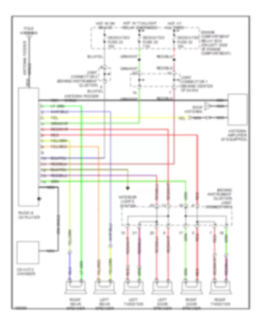
схема с 6 акустическими системами, эволюция без усилитель для Mitsubishi Lancer Evolution 2004
схема с 6 акустическими системами, эволюция без усилитель для Mitsubishi Lancer Evolution 2004 - Список элементов:
- Antenna amplifier
- Antenna feeder cable
- Cd auto changer
- Din cable
- Engine compartment relay box (on left side of engine compartment)
- Fuse 20 7.5a
- Fuse 22 10a
- Fuse 23 10a
- Hot at all times
- Hot in on or acc
- Hot w/ taillight relay energized
- Interior lights system
- Joint connector 1 (behind center of dash)
- Left front door speaker
- Left rear door speaker
- Left tweeter (w/ radio & cd player)
- Nca
- Pnk
- Radio & cd player
- Red
- Right front door speaker
- Right rear door speaker
- Right tweeter (w/ radio & cd player)
- Roof antenna
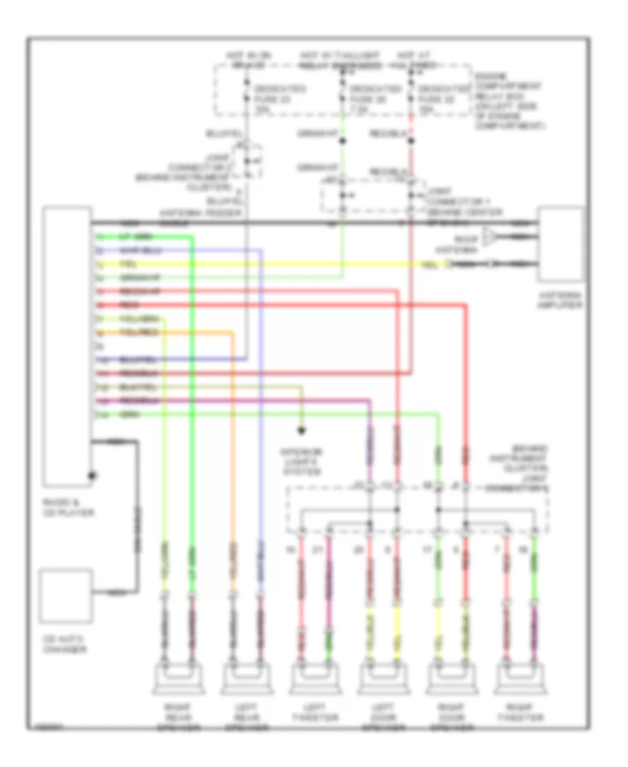
схема с 6 акустическими системами, кроме эволюции без усилитель для Mitsubishi Lancer Evolution 2004
схема с 6 акустическими системами, кроме эволюции без усилитель для Mitsubishi Lancer Evolution 2004 - Список элементов:
- (behind instrument cluster) joint connector 5
- Antenna amplifier (if equipped)
- Antenna feeder cable
- Antenna feeder nca
- Cable
- Cd auto changer
- Dedicated fuse 20 7.5a
- Dedicated fuse 22 10a
- Dedicated fuse 23 10a
- Din cable
- Engine compartment relay box (on left side of engine compartment)
- Hot at all times
- Hot in on or acc
- Hot w/ taillight relay energized
- Interior lights system
- Joint connector 1 (behind center of dash)
- Joint connector 2 (behind instrument cluster)
- Left door speaker
- Left rear speaker
- Left tweeter
- Nca
- Pole antenna
- Radio & cd player
- Red
- Right door speaker
- Right rear speaker
- Right tweeter
- Roof antenna
схема с 6 акустическими системами, Универсал для Mitsubishi Lancer Evolution 2004
схема с 6 акустическими системами, Универсал для Mitsubishi Lancer Evolution 2004 - Список элементов:
- (behind instrument cluster) joint connector 5
- Antenna amplifier
- Antenna feeder cable
- Cd auto changer
- Dedicated fuse 20 7.5a
- Dedicated fuse 22 10a
- Dedicated fuse 23 10a
- Din cable
- Engine compartment relay box (on left side of engine compartment)
- Hot at all times
- Hot in on or acc
- Hot w/ taillight relay energized
- Interior lights system
- Joint connector 1 (behind center of dash)
- Joint connector 2 (behind instrument cluster)
- Left door speaker
- Left rear speaker
- Left tweeter
- Nca
- Radio & cd player
- Red
- Right door speaker
- Right rear speaker
- Right tweeter
- Roof antenna
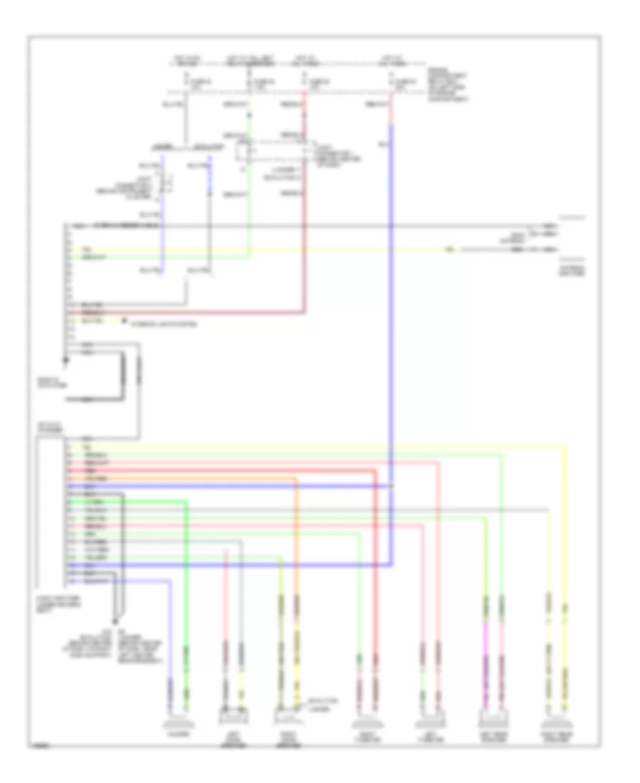
схема с 7 акустическими системами для Mitsubishi Lancer Evolution 2004
схема с 7 акустическими системами для Mitsubishi Lancer Evolution 2004 - Список элементов:
- (evolution)
- (lancer)
- Antenna amplifier
- Antenna feeder cable
- Audio amplifier (under driver's seat)
- Cd auto changer
- Din cable
- Engine compartment relay box (on left side of engine compartment)
- Evolution
- Fuse 20 7.5a
- Fuse 22 10a
- Fuse 23 10a
- Fuse 24 20a
- G16 (evolution) (behind center of dash, on right dash support)
- G6 (lancer) (behind center of dash, near left center reinforcement)
- Hot at all times
- Hot in on or acc
- Hot w/ taillight relay energized
- Interior lights system
- Joint connector 1 (behind center of dash)
- Joint connector 2 (behind instrument cluster)
- Lancer
- Left door speaker
- Left rear speaker
- Left tweeter
- Nca
- Nca nca
- Pnk
- Radio & cd player
- Red
- Right door speaker
- Right rear speaker
- Right tweeter
- Roof antenna
- Woofer
Подогрев стекол и зеркал
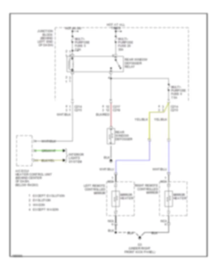
Электросхема подогрева стекол и зеркал для Mitsubishi Lancer Evolution 2004
Электросхема подогрева стекол и зеркал для Mitsubishi Lancer Evolution 2004 - Список элементов:
- A/c ecu/ heater control unit (behind center of dash, below radio)
- C214 c215
- C217 c218
- Evolution
- Except evolution
- Except wagon
- G3 (under right front kick panel)
- Hot at all times
- Hot in on
- Interior lights system
- Junction block (behind left end of dash)
- Left remote controlled mirror
- Mirror heater
- Multi- purpose fuse 20 30a
- Multi- purpose fuse 5 7.5a
- Multi- purpose fuse 6 7.5a
- Nca
- Rear window defogger
- Rear window defogger relay
- Right remote controlled mirror
- Wagon
ПОДУШКИ БЕЗОПАСНОСТИ AIR BAG
Электросхема подушек безопасности SRS AirBag, эволюция (1 из 2) для Mitsubishi Lancer Evolution 2004
Электросхема подушек безопасности SRS AirBag, эволюция (1 из 2) для Mitsubishi Lancer Evolution 2004 - Список элементов:
- (at left front of engine compartment) left front impact sensor
- (at right front of engine compartment) right front impact sensor
- (at top left side of dash) g7
- (behind center of dash, on right dash support) g16
- (partial) (below left side of
- Air bag drive circuit
- C-01
- C-02
- C-12
- C-214
- Clock spring
- Combination meter
- Connector lock switch (connector coupled: on) (connector uncoupled: off)
- Dash)
- Data
- Data link connector (dlc)
- Detection circuit
- Driver's side air bag module (squib) (in steering column)
- Fuse 7.5a
- Ground
- Hot in on or start
- Ignition
- J/c 2 (behind instrument cluster)
- J/c 4
- Junction block (behind left end of dash)
- Nca
- Off
- Srs ecu (behind lower center of dash)
- Srs indicator
- Warning light
Электросхема подушек безопасности SRS AirBag, эволюция (2 из 2) для Mitsubishi Lancer Evolution 2004
Электросхема подушек безопасности SRS AirBag, эволюция (2 из 2) для Mitsubishi Lancer Evolution 2004 - Список элементов:
- (at base of right "b" pillar, behind trim) right seat belt pretensioner
- (at right side of dash) passenger's side air bag module squib
- (connector coupled: on) (connector uncoupled: off) connector lock switch
- Air bag drive circuit
- C-13
- Connector lock switch (connector coupled: on) (connector uncoupled: off)
- Left seat belt pretensioner (at base of left "b" pillar, behind trim)
- Nca
- Off
- Red
- Srs ecu (behind lower center of dash)
Электросхема подушек безопасности SRS AirBag, кроме эволюции (1 из 2) для Mitsubishi Lancer Evolution 2004
Электросхема подушек безопасности SRS AirBag, кроме эволюции (1 из 2) для Mitsubishi Lancer Evolution 2004 - Список элементов:
- (at top left side of dash) g7
- (behind center of dash, on right dash support) g16
- (in steering wheel) driver's side air bag module squib
- (partial) (below left side of
- (right side of dash) passenger's side air bag module squib
- Air bag drive circuit
- C-12
- Clock spring
- Connector lock switch (connector coupled: on) (connector uncoupled: off)
- Connector lock switch (connector coupled: on) connector uncoupled: off)
- Dash)
- Data
- Data link connector (dlc)
- Detection circuit
- Ground
- Ignition
- J/c 2 (behind instrument cluster)
- Nca
- Off
- Right side air bag squib module (w/side air bag) (at passenger's seat)
- Srs ecu (behind lower center of dash)
- Warning light
Электросхема подушек безопасности SRS AirBag, кроме эволюции (2 из 2) для Mitsubishi Lancer Evolution 2004
Электросхема подушек безопасности SRS AirBag, кроме эволюции (2 из 2) для Mitsubishi Lancer Evolution 2004 - Список элементов:
- Air bag drive circuit
- C-01
- C-02
- C-13
- C-214
- Combination meter
- Connector lock switch (connector coupled: on) (connector uncoupled: off)
- Fuse 7.5a
- Ground
- Hot in on or start
- Interface
- J/c 5 (behind combination meter)
- Junction block (behind left end of dash)
- Left seat belt pretensioner (at base of left "b" pillar, behind trim)
- Left side air bag module squib (w/side air bags) (at driver's seat)
- Left side impact sensor (w/side air bags) (at base of left "b" pillar, behind trim)
- Nca
- Off
- Pnk
- Red
- Right seat belt pretensioner (at base of right "b" pillar, behind trim)
- Right side impact sensor (w/side air bags) (at base of right "b" pillar, behind trim)
- Solid state
- Srs ecu (behind lower center of dash)
- Srs indicator
Электросхема подушек безопасности SRS AirBag, Универсал (1 из 2) для Mitsubishi Lancer Evolution 2004
Электросхема подушек безопасности SRS AirBag, Универсал (1 из 2) для Mitsubishi Lancer Evolution 2004 - Список элементов:
- (behind center of dash, near left reinforcement) g6
- (in steering wheel) driver's side air bag module squib
- (left rear of engine compt, on shock tower) g4
- (partial) (below left side of
- (right side of dash) passenger's side air bag module squib
- Air bag drive circuit
- C-17
- Clock spring
- Connector lock switch (connector coupled: on) (connector uncoupled: off)
- Connector lock switch (connector coupled: on) connector uncoupled: off)
- Dash)
- Data
- Data link connector (dlc)
- Detection circuit
- Ground
- Ignition
- J/c 2 (behind instrument cluster)
- Nca
- Off
- Right side air bag squib module (at passenger's seat)
- Srs ecu (behind lower center of dash)
- Warning light
Электросхема подушек безопасности SRS AirBag, Универсал (2 из 2) для Mitsubishi Lancer Evolution 2004
Электросхема подушек безопасности SRS AirBag, Универсал (2 из 2) для Mitsubishi Lancer Evolution 2004 - Список элементов:
- Air bag drive circuit
- C-02
- C-04
- C-16
- C-215
- Combination meter
- Connector lock switch (connector coupled: on) (connector uncoupled: off)
- Fuse 7.5a
- Ground
- Hot in on or start
- Interface
- J/c 5 (behind combination meter)
- Junction block (behind left end of dash)
- Left seat belt pretensioner (at base of left "b" pillar, behind trim)
- Left side air bag module squib (at driver's seat)
- Left side impact sensor (at base of left "b" pillar, behind trim)
- Nca
- Off
- Pnk
- Red
- Right seat belt pretensioner (at base of right "b" pillar, behind trim)
- Right side impact sensor (at base of right "b" pillar, behind trim)
- Solid state
- Srs ecu (behind lower center of dash)
- Srs indicator
ПРЕДУПРЕЖДАЮЩИЕ СИСТЕМЫ
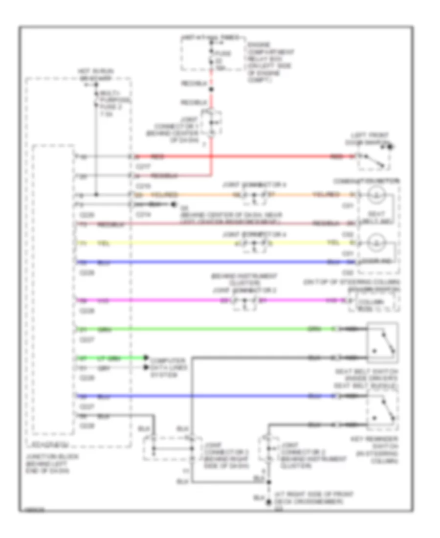
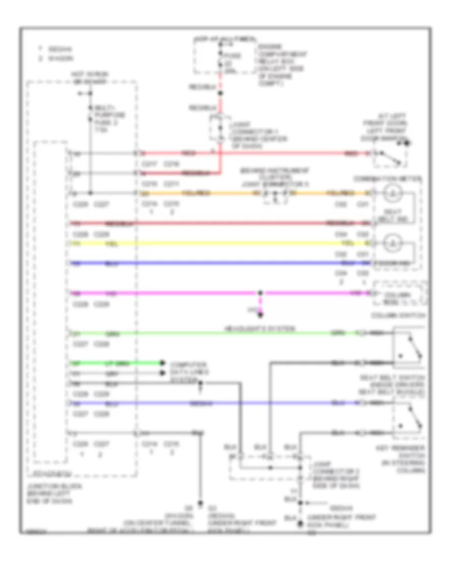
Электросхема предупреждающей системы, эволюция для Mitsubishi Lancer Evolution 2004
Электросхема предупреждающей системы, эволюция для Mitsubishi Lancer Evolution 2004 - Список элементов:
- (at right side of front deck crossmember) g3
- (behind instrument cluster) joint connector 2
- (on top of steering column) column switch
- C01
- C02
- C210
- C214
- C217
- C226
- C227
- C228
- Column ecu
- Combination meter
- Computer data lines system
- Door ind
- Engine compartment relay box (on left side of engine compt)
- Etacs-ecu
- Fuse 10a
- G6 (behind center of dash, near left center reinforcement)
- Hot at all times
- Hot in run or start
- Joint connector 1 (behind center of dash)
- Joint connector 2 (behind instrument cluster)
- Joint connector 3 (behind right side of dash)
- Joint connector 4
- Junction block (behind left end of dash)
- Key reminder switch (in steering column)
- Left front door switch
- Multi- purpose fuse 2 7.5a
- Nca
- Red
- Seat belt ind
- Seat belt switch (inside driver's seat belt buckle)
Электросхема предупреждающей системы, кроме эволюции для Mitsubishi Lancer Evolution 2004
Электросхема предупреждающей системы, кроме эволюции для Mitsubishi Lancer Evolution 2004 - Список элементов:
- (at left front door) left front door switch
- (behind instrument cluster) joint connector 5
- (under right front kick panel) g3
- C01
- C02
- C04
- C210
- C211
- C214
- C215
- C217
- C218
- C226
- C227
- C228
- C229
- Column ecu
- Column switch
- Combination meter
- Computer data lines system
- Door ind
- Engine compartment relay box (on left side of engine compt)
- Etacs-ecu
- Fuse 10a
- G3 (sedan) (under right front kick panel)
- G5 (wagon) (on center tunnel, right of accelerator pedal)
- Headlights system
- Hot at all times
- Hot in run or start
- Joint connector 1 (behind center of dash)
- Joint connector 3 (behind right side of dash)
- Junction block (behind left end of dash)
- Key reminder switch (in steering column)
- Multi- purpose fuse 2 7.5a
- Nca
- Red
- Seat belt ind
- Seat belt switch (inside driver's seat belt buckle)
- Sedan
- Wagon
ПРИБОРНАЯ ПАНЕЛЬ
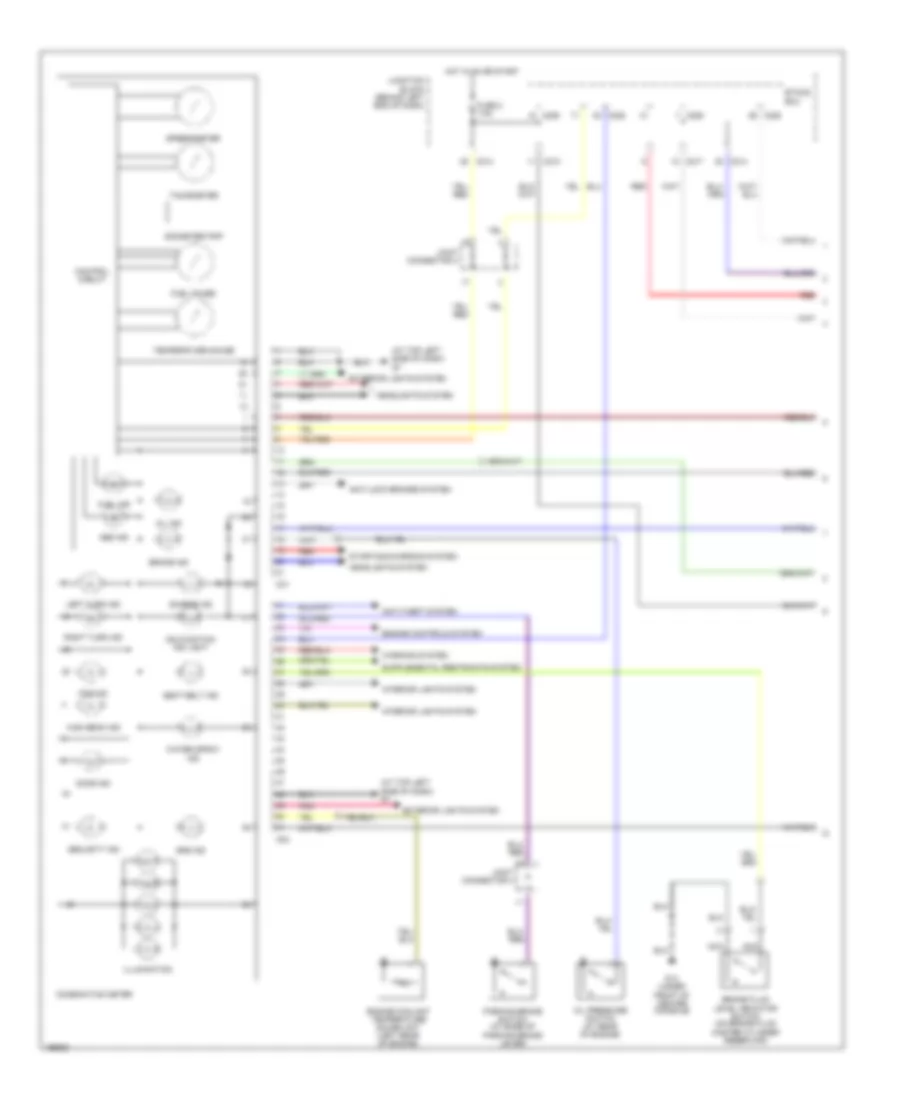
Электросхема панели приборов, эволюция (1 из 2) для Mitsubishi Lancer Evolution 2004
Электросхема панели приборов, эволюция (1 из 2) для Mitsubishi Lancer Evolution 2004 - Список элементов:
- (at top left side of dash) g7
- Abs ind
- Anti-lock brakes system
- Anti-theft system
- Brake fluid level indicator switch (on brake fluid master cylinder reservoir)
- Brake ind
- C01
- C02
- C210
- C214
- C217
- C226
- C228
- Charge ind
- Combination meter
- Control circuit
- Door ind
- Engine controls system
- Engine coolant temperature gauge unit (left rear of engine)
- Etacs ecu
- Exterior lights system
- Fog ind
- Fuel gauge
- Fuel ind
- Fuse 2 7.5a
- G14 (under front of center console)
- Headlights system
- High beam ind
- Hot in on or start
- Illumination
- Interior lights system
- Joint connector 4
- Junction block (behind left end of dash)
- Left turn ind
- Malfunction ind light
- Nca
- Odometer/trip
- Oil ind
- Oil pressure switch (at rear of engine)
- Parking brake switch (at base of parking brake lever)
- Pnk
- Red
- Right turn ind
- Seat belt ind
- Security ind
- Speedometer
- Srs ind
- Starting/charging system
- Tachometer
- Temperature gauge
- Warning system
- Water spray ind
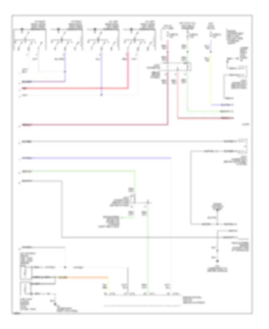
Электросхема панели приборов, эволюция (2 из 2) для Mitsubishi Lancer Evolution 2004
Электросхема панели приборов, эволюция (2 из 2) для Mitsubishi Lancer Evolution 2004 - Список элементов:
- (at left front door) left front door switch
- (at left rear door) left rear door switch
- (at right front door) right front door switch
- (at right rear door) right rear door switch
- (on top right side of fuel tank) fuel level sensor (sub)
- (under right front kick panel) g3
- C115
- C117
- C119
- Clock
- Detection connector (in engine compt relay box)
- Engine compartment relay box (on left side of engine compt)
- Engine control module (behind glove box)
- Engine controls system
- Engine speed
- Fuel pump & level sensor (main) (in fuel tank)
- Fuse 20 7.5a
- Fuse 22 10a
- Fuse 23 10a
- G14 (under front of center console)
- G2 (under right front kick panel)
- Hot at all times
- Hot in on or acc
- Hot with tail- light relay energized
- Joint connector (behind center of dash)
- Joint connector 3 (behind right side of dash)
- Joint connector 5 (behind instrument cluster)
- Joint connector 6 (behind lower center of dash)
- Nca
- Red
- Vehicle speed sensor (on right side of transaxle)
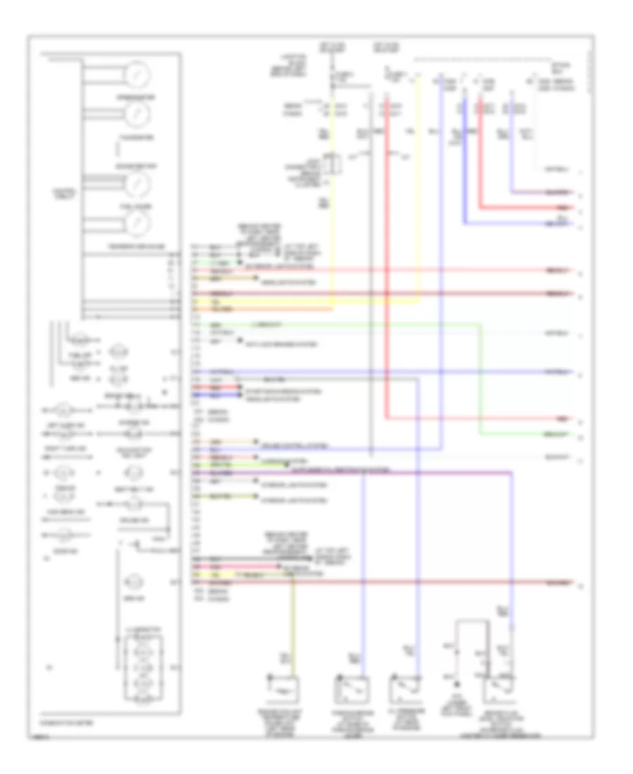
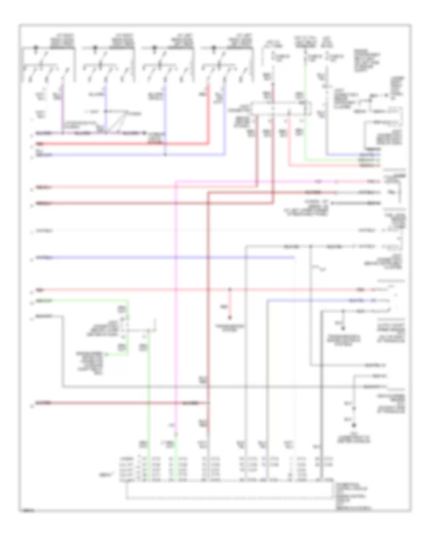
Электросхема панели приборов, кроме эволюции (1 из 2) для Mitsubishi Lancer Evolution 2004
Электросхема панели приборов, кроме эволюции (1 из 2) для Mitsubishi Lancer Evolution 2004 - Список элементов:
- (at top left side of dash) g7
- (behind center of dash, near left center reinforcement) (at top left g6 side of dash) g7
- (behind center of dash, near left center reinforcement) g6
- (sedan)
- (wagon)
- A/t
- Abs ind
- Anti-lock brakes system
- Brake fluid level indicator switch (on brake fluid master cylinder reservoir)
- Brake ind
- C01
- C02
- C04
- C210
- C211
- C214
- C214 c215
- C215
- C217 c218
- C226
- C227
- C228
- C228 (sedan)
- C229
- C229 (wagon)
- Charge ind
- Combination meter
- Control circuit
- Cruise control system
- Cruise ind
- Door ind
- Engine coolant temperature gauge unit (left rear of engine)
- Etacs ecu
- Exterior lights system
- Exterior lights system
- Fog ind
- Fuel gauge
- Fuel ind
- Fuse 2 7.5a
- Fuse 3 7.5a
- G15 (under left front kick panel)
- Headlights system
- High beam ind
- Hot in on or start
- Illumination
- Interior lights system
- Joint connector 5 (behind instrument cluster)
- Junction block (behind left end of dash)
- Left turn ind
- M/t
- Malfunction ind light
- Nca
- Odometer/trip
- Oil ind
- Oil pressure switch (at rear of engine)
- Parking brake switch (at base of parking brake lever)
- Pnk
- Red
- Right turn ind
- Seat belt ind
- Sedan
- Speedometer
- Srs ind
- Starting/charging system
- Tachometer
- Temperature gauge
- Wagon
- Warning system
Электросхема панели приборов, кроме эволюции (2 из 2) для Mitsubishi Lancer Evolution 2004
Электросхема панели приборов, кроме эволюции (2 из 2) для Mitsubishi Lancer Evolution 2004 - Список элементов:
- (at left front door) left front door switch
- (at left rear door) left rear door switch
- (at right front door) right front door switch
- (at right rear door) right rear door switch
- (sedan)
- (under right front kick panel) g3
- (wagon)
- 2.0l a/t
- 2.0l m/t
- 2.4l a/t
- 2.4l m/t
- C112
- C114
- C115
- C116
- C117
- C118
- C119
- C120
- C133
- C134
- C137
- C138
- Clock
- Detection connector (in engine compt relay box)
- Engine compartment relay box (on left side of engine compt)
- Engine speed
- Fuel level sensor (in fuel tank)
- Fuse 20 7.5a
- Fuse 22 10a
- Fuse 23 10a
- G14 (under front of center console)
- G17
- G9 (at left upper corner of rear shelf panel)
- Hot at all times
- Hot in on or acc
- Hot w/ tail- light relay energized
- Interior lights system
- Joint connector (behind center of dash)
- Joint connector 2 (behind instrument cluster)
- Joint connector 3 (behind right side of dash)
- Joint connector 5 (behind instrument cluster)
- Joint connector 6 (behind lower center of dash)
- Liftgate switch (wagon)
- M/t
- Output shaft speed sensor (a/t) (on top right of transaxle)
- Pnk
- Powertrain control module (a/t) engine control module (m/t) (behind glove box)
- Red
- Sedan
- Transmissions & engine controls systems
- Transmissions system
- Vehicle speed sensor (m/t) (on right side of transaxle)
- Wagon
ПРИВОД ЗЕРКАЛ
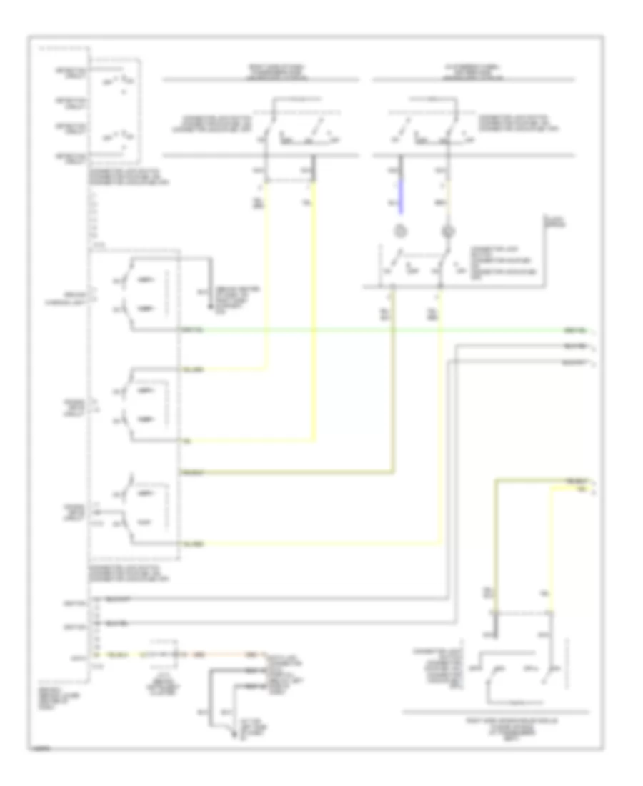
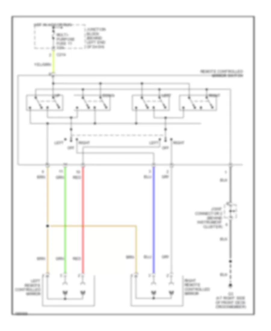
Электросхема привода зеркал, эволюция для Mitsubishi Lancer Evolution 2004
Электросхема привода зеркал, эволюция для Mitsubishi Lancer Evolution 2004 - Список элементов:
- C214
- Down
- G3 (at right side of front deck crossmember)
- Hot in acc or run
- Joint connector 2 (behind instrument cluster)
- Junction block (behind left end of dash)
- Left
- Left remote controlled mirror
- Multi- purpose fuse 11 7.5a
- Off
- Red
- Remote controlled mirror switch
- Right
- Right remote controlled mirror
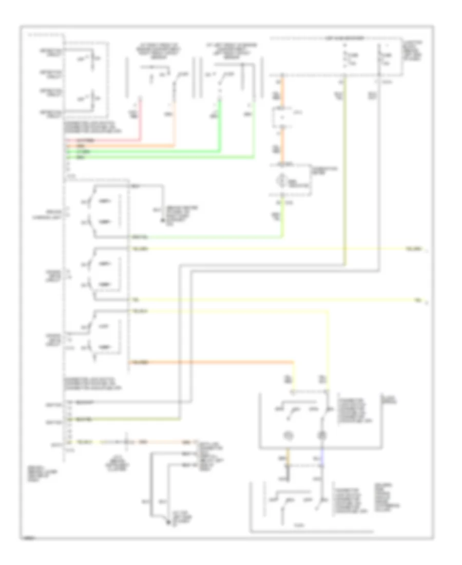
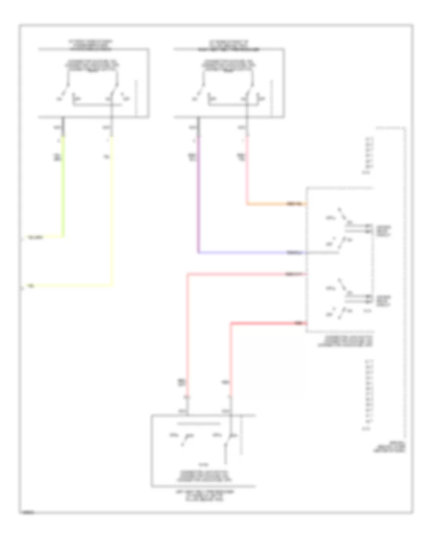
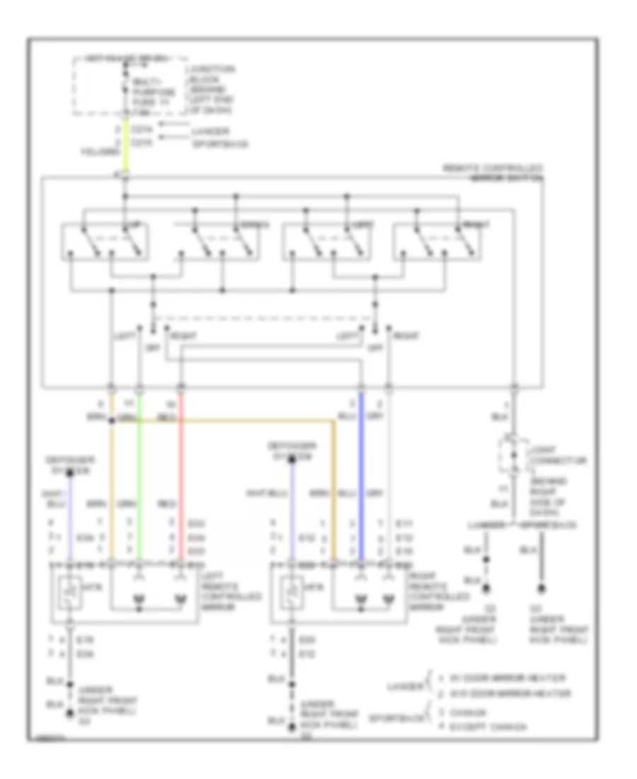
Электросхема привода зеркал, кроме эволюции для Mitsubishi Lancer Evolution 2004
Электросхема привода зеркал, кроме эволюции для Mitsubishi Lancer Evolution 2004 - Список элементов:
- (under right front kick panel) g3
- C214
- Canada
- Defogger system
- Down
- E03
- E04
- E10
- E11
- E12
- E19
- E20
- Except canada
- G3 (under right front kick panel)
- Hot in acc or on
- Htr
- Joint connector (behind right side of dash)
- Junction block (behind left end of dash)
- Lancer
- Left
- Left remote controlled mirror
- Multi- purpose fuse 11 7.5a
- Off
- Red
- Remote controlled mirror switch
- Right
- Right remote controlled mirror
- Sportback
- W/ door mirror heater
- W/o door mirror heater
ПРИВОД ЛЮКА И КРЫШИ
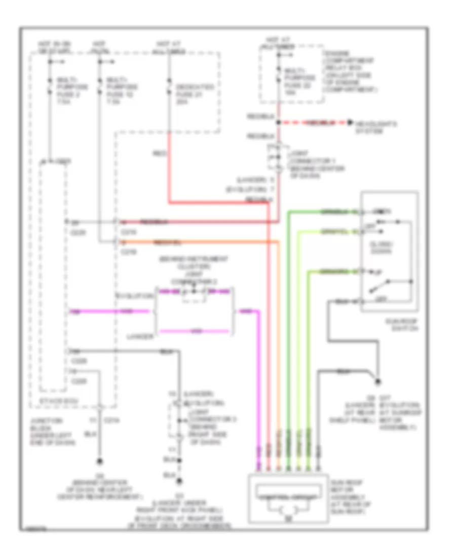
Электросхема привода люка или крыши для Mitsubishi Lancer Evolution 2004
Электросхема привода люка или крыши для Mitsubishi Lancer Evolution 2004 - Список элементов:
- (behind instrument cluster) joint connector 2
- (evolution)
- (evolution: at right side of front deck crossmember)
- (lancer)
- C210
- C214
- C218
- C226
- C228
- Close/ down
- Control circuit
- Dedicated fuse 21 20a
- Engine compartment relay box (on left side of engine compartment)
- Etacs ecu
- Evolution
- G3 (lancer: under right front kick panel)
- G6 (behind center of dash, near left center reinforcement)
- G8 g17 (evolution) (lancer) (at rear (at sunroof motor assembly)
- Headlights system
- Hot at all times
- Hot in on
- Hot in on or start
- Joint connector 1 (behind center of dash)
- Joint connector 3 (behind right side of dash)
- Junction block (under left end of dash)
- Lancer
- Multi- purpose fuse 12 7.5a
- Multi- purpose fuse 2 7.5a
- Multi- purpose fuse 22 10a
- Off
- Open
- Red
- Shelf panel)
- Sun roof motor assembly (at rear of sun roof)
- Sun roof switch
ПРИВОД СТЕКЛОПОДЪЕМНИКОВ
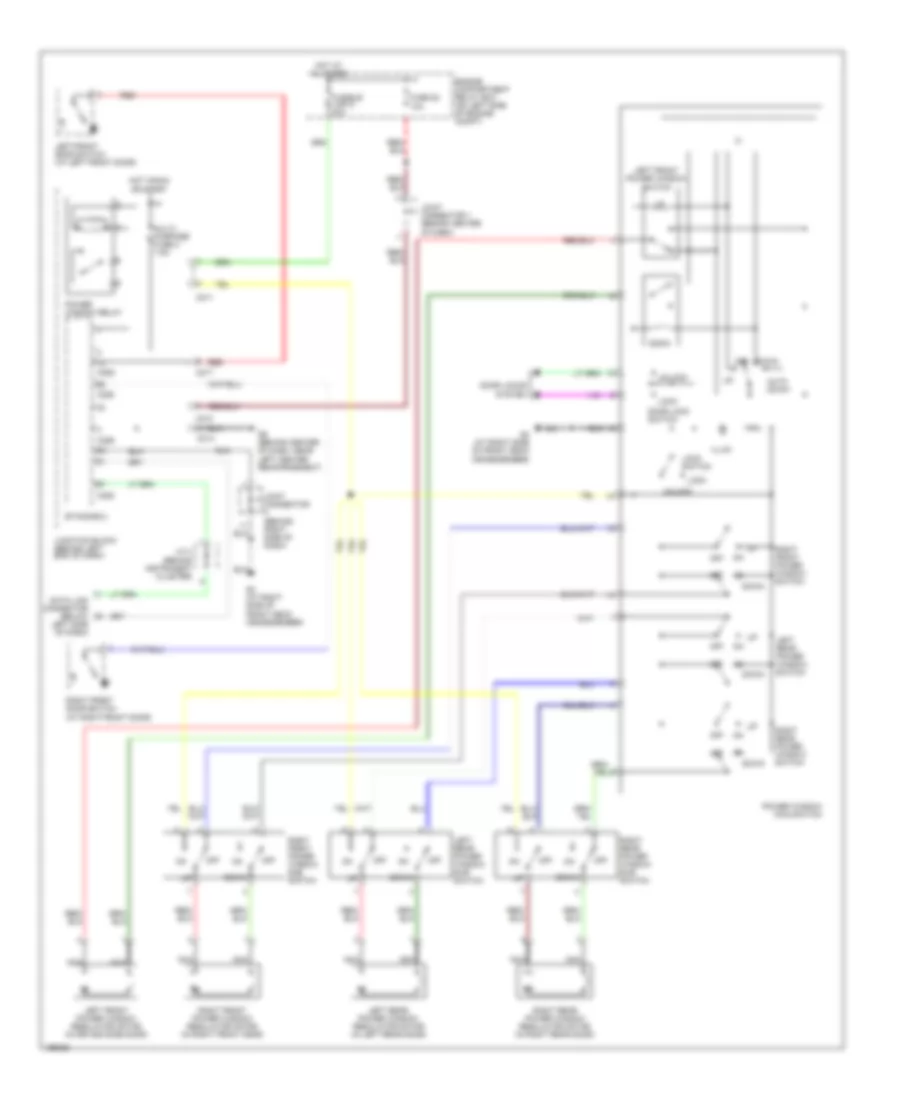
Электросхема стеклоподъемников, эволюция для Mitsubishi Lancer Evolution 2004
Электросхема стеклоподъемников, эволюция для Mitsubishi Lancer Evolution 2004 - Список элементов:
- Auto down
- C210
- C211
- C214
- C217
- C226
- C228
- Data link connector (below left side of dash)
- Door lock switch
- Door locks system
- Down
- Engine compartment relay box (on left side of engine compt)
- Etacs-ecu
- Fuse 22 10a
- Fusible link 5 30a
- G3 (at right side of front deck crossmember)
- G6 (behind center of dash, near left center reinforcement)
- Hot at all times
- Hot in run or start
- Illum
- J/c 4 (behind instrument cluster)
- Joint connector (behind right side of dash)
- Joint connector 1 (behind center of dash)
- Junction block (behind left end of dash)
- Left front door switch (at left front door)
- Left front power window regulator motor (in drive's side door)
- Left front power window switch
- Left rear power window switch
- Left rear power window regulator motor (in left rear door)
- Left rear power window sub switch
- Lock
- Lock switch
- Multi- purpose fuse 2 7.5a
- Nca
- Off
- Power window main switch
- Power window relay
- Red
- Right front door switch (at right front door)
- Right front power window switch
- Right front power window regulator motor (in right front door)
- Right front power window sub switch
- Right rear power window switch
- Right rear power window regulator motor (in right rear door)
- Right rear power window sub switch
- Unlock
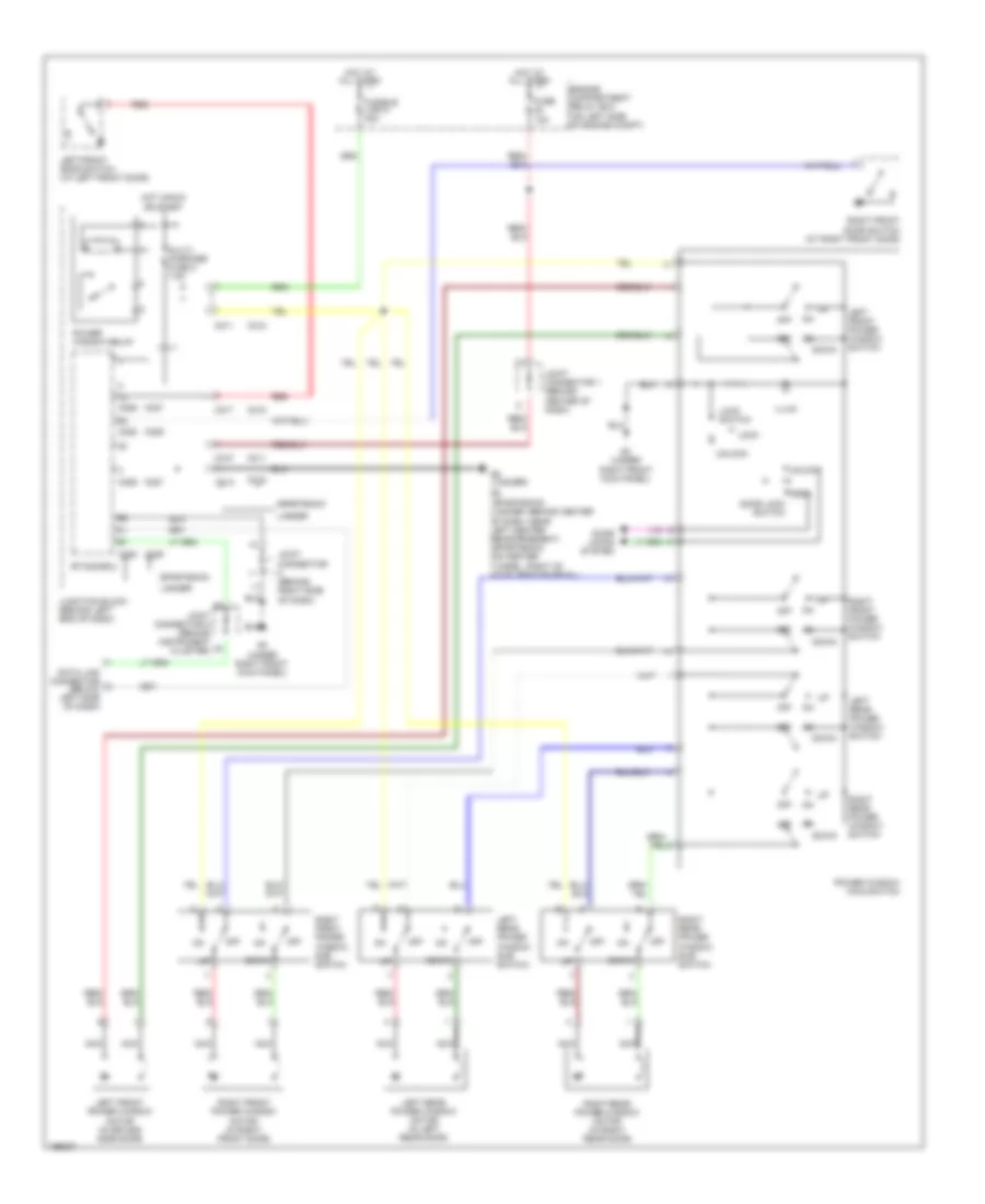
Электросхема стеклоподъемников, кроме эволюции для Mitsubishi Lancer Evolution 2004
Электросхема стеклоподъемников, кроме эволюции для Mitsubishi Lancer Evolution 2004 - Список элементов:
- C210
- C211
- C212
- C214
- C215
- C217
- C218
- C226
- C227
- C228
- C229
- Data link connector (below left side of dash)
- Door lock switch
- Door locks system
- Down
- Engine compartment relay box (on left side of engine compt)
- Etacs-ecu
- Fuse 10a
- Fusible link 5 30a
- G3 (under right front kick panel)
- G5 (sportback) (lancer: behind center of dash, near left center reinforcement) (sportback) (on center tunnel, right of accelerator pedal)
- G6 (lancer)
- Hot at all times
- Hot in run or start
- Illum
- Joint connector (behind right side of dash)
- Joint connector 1 (behind center of dash)
- Joint connector 2 (behind instrument cluster)
- Junction block (behind left end of dash)
- Lancer
- Left front door switch (at left front door)
- Left front power window switch
- Left front power window motor (in drive's side door)
- Left rear power window switch
- Left rear power window motor (in left rear door)
- Left rear power window sub switch
- Lock
- Lock switch
- Multi- purpose fuse 2 7.5a
- Nca
- Off
- Power window main switch
- Power window relay
- Red
- Right front door switch (at right front door)
- Right front power window switch
- Right front power window motor (in right front door)
- Right front power window sub switch
- Right rear power window switch
- Right rear power window motor (in right rear door)
- Right rear power window sub switch
- Sportback
- Unlock
Противоугонная система Сигнализация
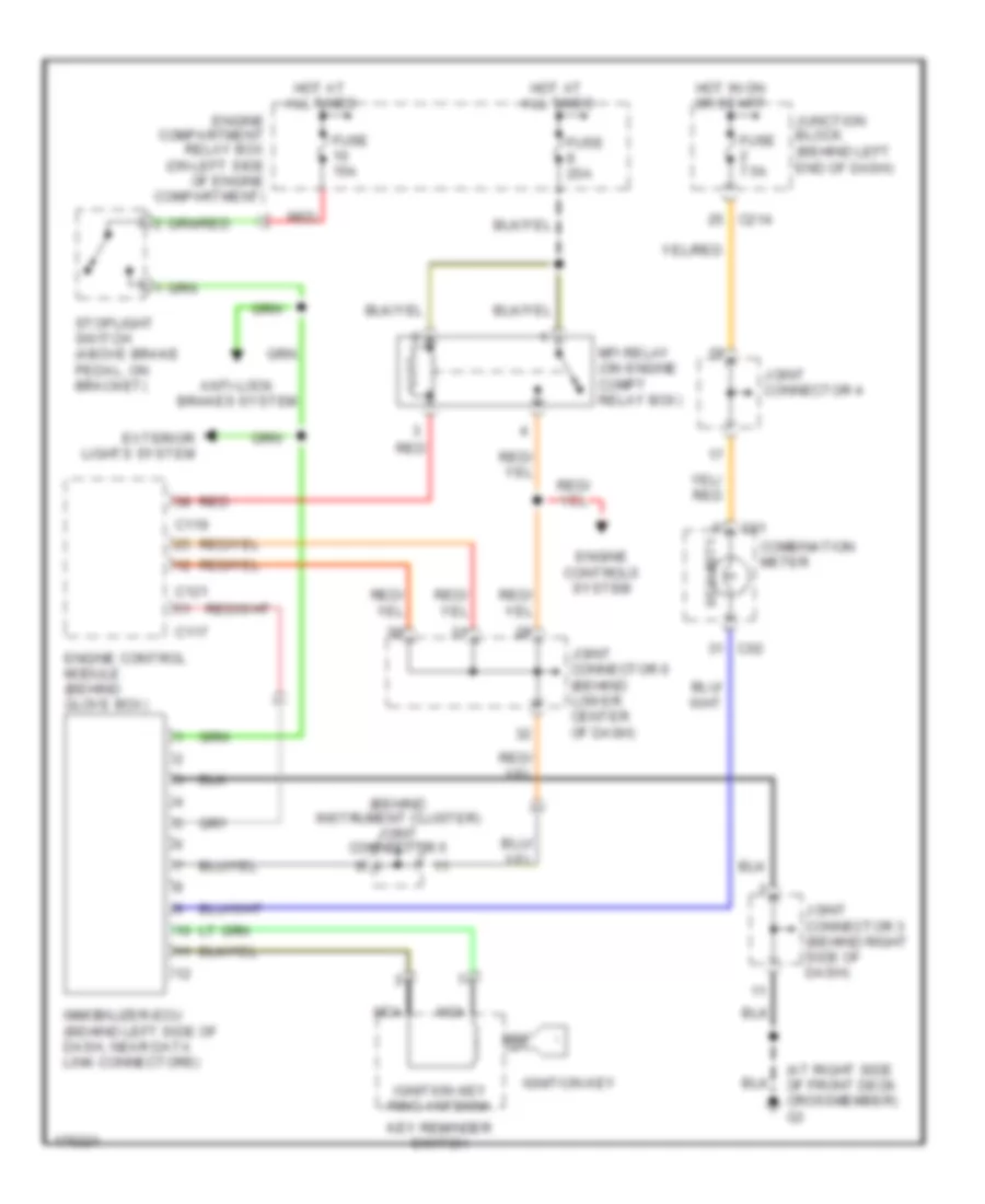
Электросхема иммобилайзера, эволюция для Mitsubishi Lancer Evolution 2004
Электросхема иммобилайзера, эволюция для Mitsubishi Lancer Evolution 2004 - Список элементов:
- (at right side of front deck crossmember) g3
- (behind instrument cluster) joint connector 5
- All times
- Anti-lock brakes system
- C01
- C02
- C117
- C119
- C121
- C214
- Combination meter
- Engine compartment relay box (on left side of engine compartment)
- Engine control module (behind glove box)
- Engine controls system
- Exterior lights system
- Fuse 15a
- Fuse 20a
- Fuse 7.5a
- Hot at
- Hot in on or start
- Ignition key
- Ignition key ring antenna
- Immobilizer-ecu (behind left side of dash, near data link connectors)
- Joint connector 3 (behind right side of dash)
- Joint connector 4
- Joint connector 6 (behind lower center of dash)
- Junction block (behind left end of dash)
- Key reminder switch
- Mfi relay (on engine compt relay box)
- Nca
- Red
- Security
- Stoplight switch (above brake pedal, on bracket)
СИСТЕМА АНТИБЛОКИРОВОЧНОЙ ТОРМОЗНОЙ СИСТЕМЫ ABS
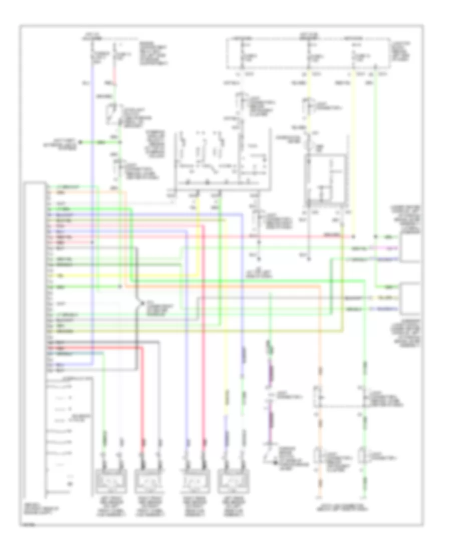
Электросхема антиблокировочной тормозной системы АБС (ABS), эволюция для Mitsubishi Lancer Evolution 2004
Электросхема антиблокировочной тормозной системы АБС (ABS), эволюция для Mitsubishi Lancer Evolution 2004 - Список элементов:
- (under center console, left of parking brake lever assembly) (lateral) g-sensor
- Abs ecu (on right rear of engine compt)
- Abs ind
- Anti-theft, exterior lights systems
- C01
- C02
- C210
- C214
- Combination meter
- Data link connector (below left side of dash)
- Engine compartment relay box (on left side of engine compartment)
- Fuse 10 15a
- Fuse 12 7.5a
- Fuse 2 7.5a
- Fuse 5 7.5a
- Fusible link 3 60a
- G-sensor (longitudinal) (under center console, left of parking brake lever assembly)
- G14 (under front of center console)
- G7 (at top left side of dash)
- Hot at all times
- Hot in on
- Hot in on or start
- Hydraulic unit
- Joint connector 2 (behind instrument cluster)
- Joint connector 3 (behind right side of dash)
- Joint connector 4
- Joint connector 6 (behind lower center of dash)
- Junction block (behind left end of dash)
- Left front abs sensor (on left front wheel hub assembly)
- Left rear abs sensor (on left rear hub assembly)
- Nca
- Parking brake switch (at base of parking brake lever)
- Pnk
- Red
- Right front abs sensor (on right front wheel hub assembly)
- Right rear abs sensor (on right rear hub assembly)
- Solenoid valve
- Steering angular velocity sensor (at top of steering column)
- Stoplight switch (above brake pedal, on bracket)
Электросхема антиблокировочной тормозной системы АБС (ABS), кроме эволюции для Mitsubishi Lancer Evolution 2004
Электросхема антиблокировочной тормозной системы АБС (ABS), кроме эволюции для Mitsubishi Lancer Evolution 2004 - Список элементов:
- (lancer) (under front of center console)
- Abs ecu (on right rear of engine compartment)
- Abs ind
- Abs solenoid valve
- Abs warning light relay (on junction block)
- C01 c02
- C02 c01
- C210 c211
- C214 c215
- Combination meter
- Cpu
- Data link connector (below left side of dash)
- Dedicated fuse 10 15a
- Engine compartment relay box (on left side of engine compartment)
- Exterior lights systems
- Fusible link 3 60a
- G14 g15 (sportback) (under left front kick panel)
- G3 (under right front kick panel)
- Hot at all times
- Hot in on
- Hot in on or start
- Hydraulic unit
- Joint connector 5 (behind instrument cluster)
- Joint connector 2 (behind instrument cluster)
- Joint connector 3 (behind right side of dash)
- Joint connector 6 (behind lower center of dash)
- Junction block (behind left end of dash)
- Lancer sportback
- Left front wheel speed sensor (on left front wheel hub assembly)
- Left rear wheel speed sensor (at left rear wheel)
- Multi- purpose fuse 12 7.5a
- Multi- purpose fuse 2 7.5a
- Nca
- Pnk
- Red
- Right front wheel speed sensor (on right front wheel hub assembly)
- Right rear wheel speed sensor (at right rear wheel)
- Sportback lancer
- Stoplight switch (above brake pedal, on bracket)
СИСТЕМА КОНДИЦИОНЕРА
Электросхема кондиционера с ручный управлением, Эволюция (1 из 2) для Mitsubishi Lancer Evolution 2004
Электросхема кондиционера с ручный управлением, Эволюция (1 из 2) для Mitsubishi Lancer Evolution 2004 - Список элементов:
- (behind instrument cluster)
- A/c ecu
- A/c switch, outside/inside air selection damper control & illumination
- A17
- A17-1
- Air thermo sensor (behind right center of of dash, on hvac unit)
- Blower motor (behind right end of dash)
- Blower relay
- Blower switch
- C210
- C211
- C214
- Cooling fan motor
- Defogger system
- Fan control module (on fan shroud, at left front of engine compt)
- Fuse 30a
- Fuse 7.5a
- G13 (at left front corner of engine compartment)
- G3 (at right side of front deck crossmember)
- G6 (behind center of dash, near left center reinforcement)
- G7 (at top left side of dash)
- Hot at all times
- Hot in on
- Inlet side
- Interior lights system
- Joint connector 2
- Joint connector 3 (behind right side of dash)
- Junction block (behind left end of dash)
- Nca
- Off
- Outlet side
- Outside/inside air selection damper control motor (behind upper right end of dash)
- Pnk
- Resistor (behind right side of dash, on hvac unit)
Электросхема кондиционера с ручный управлением, Эволюция (2 из 2) для Mitsubishi Lancer Evolution 2004
Электросхема кондиционера с ручный управлением, Эволюция (2 из 2) для Mitsubishi Lancer Evolution 2004 - Список элементов:
- (on engine compt relay box)
- (on left side of engine compt) engine compartment relay box
- A/c compressor
- A/c compressor clutch
- A/c compressor control relay
- A/c refrigerant temperature switch
- A34
- A35
- C115
- C119
- C121
- Condenser fan control relay (high) (on engine compt relay box)
- Condenser fan control relay (low)
- Condenser fan motor (mounted on rear of radiator)
- Dual pressure switch (on right side of engine compartment)
- Engine compartment relay box (on left side of engine compt)
- Engine control module (behind glove box)
- Engine controls system
- Engine coolant temperature sensor (on rear of cylinder head)
- Fan control relay
- Fuse 10a
- Fuse 20a
- Fuse 30a
- Fuse 7.5a
- Fusible link 2 50a
- G13 (at left front corner of engine compartment)
- G13 (at left front corner of engine compt)
- Headlights, exterior lights & wiper/washer systems
- High pressure side on-off: 2940 kpa off-on: 2350 kpa
- Hot at all times
- Hot w/ taillight relay energized
- Joint connector 1 (behind center of dash)
- Joint connector 6 (behind lower center of dash)
- Low pressure side on-off: 196 kpa off-on: 221 kpa
- Mfi relay
- Nca
- Off
- Pnk
- Red
Электросхема кондиционера с ручный управлением, Кроме Эволюции (1 из 2) для Mitsubishi Lancer Evolution 2004
Электросхема кондиционера с ручный управлением, Кроме Эволюции (1 из 2) для Mitsubishi Lancer Evolution 2004 - Список элементов:
- (behind instrument cluster)
- A/c ecu (behind center of dash, below radio)
- A17
- A17-1
- A17-2
- A18
- A18-1
- A18-2
- Air thermo sensor (behind right center of of dash, on hvac unit)
- Blower motor (behind right end of dash)
- Blower relay
- Blower switch
- C210 c211
- C211 c212
- C214 c215
- Condenser fan motor (mounted on rear of radiator)
- Defogger system
- Fan control module (on fan shroud, at left front of engine compartment)
- Fuse 30a
- Fuse 7.5a
- G12 (sportback) (at left front of engine compartment, left of battery)
- G13 (lancer) (at left front corner of engine compartment)
- G3 (under right front kick panel)
- G5 (sportback) (on center tunnel, right of accelerator pedal)
- G6 (lancer) (behind center of dash, near left center reinforcement)
- Heater control panel & illumination
- Hot at all times
- Hot in on
- Inlet side
- Interior lights system
- Joint connector 2
- Joint connector 3 (behind right side of dash)
- Junction block (behind left end of dash)
- Lancer
- Lancer sportback
- Nca
- Off
- Outlet side
- Outside/inside air selection damper control motor (behind upper right end of dash)
- Radiator fan motor
- Resistor (behind right side of dash, on hvac unit)
- Sportback
Электросхема кондиционера с ручный управлением, Кроме Эволюции (2 из 2) для Mitsubishi Lancer Evolution 2004
Электросхема кондиционера с ручный управлением, Кроме Эволюции (2 из 2) для Mitsubishi Lancer Evolution 2004 - Список элементов:
- 2.0l a/t
- 2.0l m/t
- 2.4l
- 2.4l a/t
- 2.4l m/t
- A/c compressor assembly
- A/c compressor clutch
- A/c compressor clutch relay
- A/c refrigerant temperature switch (on-off: 150 degrees centigrade) (off-on: 120 degrees centigrade)
- C111
- C112
- C113
- C114
- C115
- C116
- C118
- C119
- C120
- C121
- C133
- C134
- C135
- C136
- C137
- C138
- C139
- C140
- Dual pressure switch (on right front of engine compt)
- Engine compartment relay box (on left side of engine compartment)
- Engine compartment relay box (on left side of engine compt)
- Engine controls system
- Engine coolant temperature sensor (on rear of cylinder head)
- Exterior lights system
- Fan control relay
- Fuse 10a
- Fuse 20a
- Fuse 7.5a
- Fusible link 2 50a
- G12 (sportback) (at left front of engine compt, left of battery)
- G13 (lancer) (at left front corner of engine compt)
- High pressure side on-off: 3138 kpa off-on: 2550 kpa
- Hot at all times
- Hot w/ taillight relay energized
- Joint connector 1 (behind center of dash)
- Joint connector 6 (behind lower center of dash)
- Lancer
- Low pressure side on-off: 196 kpa off-on: 221 kpa
- Mfi relay
- Nca
- Off
- Pnk
- Powertrain control module (a/t) engine control module (m/t) (behind glove box)
- Red
- Sportback
СИСТЕМА КРУИЗКОНТРОЛЯ
2.0L
2.0L, Электросхема системы круизконтроля, A/T для Mitsubishi Lancer Evolution 2004
2.0L, Электросхема системы круизконтроля, A/T для Mitsubishi Lancer Evolution 2004 - Список элементов:
- (behind lower center of dash) joint connector 6
- Auto cruise control ecu (behind right end of dash)
- Auto cruise control switch
- Auto-cruise control vacuum pump (on right front of engine compartment)
- C01
- C02
- C114
- C116
- C118
- C120
- C204
- C214
- C229
- Cancel
- Clock spring
- Combination meter
- Computer data lines system
- Control valve
- Cruise ind
- Engine compartment relay box (on left side of engine compartment)
- Engine controls system
- Exterior lights system
- Fuse 10 15a
- Fuse 2 7.5a
- Fuse 4 7.5a
- G14 (under front of center console)
- Hot at all times
- Hot in on or start
- Joint connector 5 (behind instrument cluster)
- Joint connector 6 (behind lower center of dash)
- Junction block (behind left end of dash)
- Main
- Nca
- Off
- Output shaft speed sensor (on top right of transaxle)
- Powertrain control module (behind glove box)
- Red
- Release valve
- Resume
- Set
- Starting/ charging system
- Stoplight switch (above brake pedal, on bracket)
- Throttle position sensor (on throttle body)
2.0L, Электросхема системы круизконтроля, M/T для Mitsubishi Lancer Evolution 2004
2.0L, Электросхема системы круизконтроля, M/T для Mitsubishi Lancer Evolution 2004 - Список элементов:
- (above brake pedal, on bracket) stoplight switch
- (behind lower center of dash) joint connector 6
- Auto cruise control ecu (behind right end of dash)
- Auto cruise control switch
- Auto-cruise control vacuum pump (on right front of engine compartment)
- C-210
- C01
- C02
- C115
- C204
- C214
- C229
- Cancel
- Clock spring
- Clutch pedal position switch (above clutch pedal, on bracket)
- Combination meter
- Computer data lines system
- Control valve
- Cruise ind
- Engine compartment relay box (on left side of engine compartment)
- Engine control module (behind glove box)
- Engine controls system
- Exterior lights system
- Fuse 10 15a
- Fuse 2 7.5a
- Fuse 4 7.5a
- G14 (under front of center console)
- G15 (under left front kick panel)
- Hot at all times
- Hot in on or start
- Joint connector 6 (behind lower center of dash)
- Junction block (behind left end of dash)
- Main
- Nca
- Off
- Red
- Release valve
- Resume
- Set
- Throttle position sensor (on throttle body)
- Vehicle speed sensor (at left side of engine compartment)
2.4L
2.4L, Электросхема системы круизконтроля, A/T для Mitsubishi Lancer Evolution 2004
2.4L, Электросхема системы круизконтроля, A/T для Mitsubishi Lancer Evolution 2004 - Список элементов:
- (above brake pedal, on bracket)
- (lancer) (under left
- (under right front kick panel) g2
- Acc
- Accelerator pedal position sensor (right side of engine compartment)
- Auto-cruise control switch
- C-01 c-02
- C-02
- C-04
- C-110
- C-111
- C-112
- C-113
- C-114
- C-134
- C-136
- C-138
- C-140
- C-142
- C-204
- C-205
- C-206
- C-210
- C-211
- C-214
- C-215
- C-229
- Can
- Clock spring
- Combination meter
- Computer data lines system
- Cruise ind
- Engine compartment relay box (on left side of engine compartment)
- Engine controls system
- Exterior lights system
- Fuse 15a
- Fuse 20a
- Fuse 7.5a
- G14 g15 (sportback) (under left front front kick panel)
- Hot at all times
- Hot in on or start
- Ignition switch
- Joint connector 5 (behind instrument cluster)
- Joint connector 6 (behind lower center of dash)
- Junction block (behind left end of dash)
- Kick panel)
- Lancer
- Lock
- Main
- Mfi relay (on engine compartment relay box)
- Off
- On off
- Output shaft speed sensor (on top right of transaxle)
- Powertrain control module
- Red
- Res
- Set
- Sportback
- Start
- Starting/ charging system
- Stoplight switch
- Throttle actuator control motor
- Throttle actuator control motor relay (on engine compt relay box)
- Throttle position sensor (on throttle body)
- Transmission range switch
- Transmissions system
2.4L, Электросхема системы круизконтроля, M/T для Mitsubishi Lancer Evolution 2004
2.4L, Электросхема системы круизконтроля, M/T для Mitsubishi Lancer Evolution 2004 - Список элементов:
- (above clutch pedal, on) bracket) clutch pedal position switch
- Accelerator pedal position sensor (right side of engine compartment)
- Auto-cruise control switch
- C-01
- C-02
- C-133
- C-135
- C-137
- C-139
- C-141
- C-204
- C-210
- C-214
- C-229
- Can
- Clock spring
- Combination meter
- Computer data lines system
- Cruise ind
- Engine compartment relay box (on left side of engine compartment)
- Engine control module (behind glove box)
- Engine controls system
- Exterior lights system
- Fuse 15a
- Fuse 20a
- Fuse 7.5a
- G14 (under front of center console)
- G14 (under left front kick panel)
- G15 (under left front kick panel)
- G2 (under right front kick panel)
- Hot at all times
- Hot in on or start
- Joint connector 5 (behind instrument cluster)
- Joint connector 6 (behind lower center of dash)
- Junction block (behind left end of dash)
- Main
- Mfi relay (on engine compartment relay box)
- Off
- Red
- Res
- Set
- Stoplight switch (above brake pedal, on bracket)
- Throttle actuator control motor
- Throttle actuator control motor relay (on engine compt relay box)
- Throttle position sensor (on throttle body)
- Vehicle speed sensor
СИСТЕМА ОХЛАЖДЕНИЯ
Электросхема системы охлаждения, эволюция для Mitsubishi Lancer Evolution 2004
Электросхема системы охлаждения, эволюция для Mitsubishi Lancer Evolution 2004 - Список элементов:
- (low)
- (mounted on rear of radiator)
- A17
- A17-1
- A34
- A35
- C115
- C119
- C121
- C210
- Condenser fan control relay (high) (on engine compt relay box)
- Condenser fan control relay (on engine compt relay box)
- Condenser fan motor
- Cooling fan motor
- Engine compartment relay box (on left side of engine compt)
- Engine control module (behind glove box)
- Engine controls system
- Engine coolant temperature sensor (on rear of cylinder head)
- Fan control module (on fan shroud, at left front of engine compt)
- Fan control relay (on engine compartment relay box)
- Fuse 11 30a
- Fuse 25 30a
- Fuse 5 7.5a
- Fuse 8 20a
- Fusible link 2 50a
- G13 (at left front corner of engine compt)
- Headlights, exterior lights & wiper/washer systems
- Hot at all times
- Hot in on
- Joint connector 2 (behind instrument cluster)
- Joint connector 6 (behind lower center of dash)
- Mfi relay (on engine compartment relay box)
- Nca
- Red
Электросхема системы охлаждения, кроме эволюции для Mitsubishi Lancer Evolution 2004
Электросхема системы охлаждения, кроме эволюции для Mitsubishi Lancer Evolution 2004 - Список элементов:
- (lancer)
- (mounted on rear of radiator) condenser fan motor
- (sportback)
- 2.0l
- 2.4l
- A/t
- A17
- A17-1
- A17-2
- A18
- A18-1
- A18-2
- C111
- C113
- C114
- C115
- C118
- C119
- C120
- C121
- C133
- C134
- C135
- C136
- C139
- C140
- Engine compartment relay box (on left side of engine compartment)
- Engine controls system
- Engine coolant temperature sensor (on rear of cylinder head)
- Fan control module (on fan shroud, at left front of engine compt)
- Fan control relay (on engine compartment relay box)
- Fuse 8 20a
- Fusible link 2 50a
- G13 (at left front corner of engine compt) g12 (at left front of engine compt, left of battery)
- Hot at all times
- Joint connector 6 (behind lower center of dash)
- Lancer
- M/t
- Mfi relay (on engine compartment relay box)
- Nca
- Powertrain control module (a/t) engine control module (m/t) (behind glove box)
- Radiator fan motor
- Red
- Sportback
СИСТЕМА ПЕРЕДАЧИ ДАННЫХ
Электросхема линии передачи данных CAN, эволюция для Mitsubishi Lancer Evolution 2004
Электросхема линии передачи данных CAN, эволюция для Mitsubishi Lancer Evolution 2004 - Список элементов:
- (behind instrument cluster)
- (on right side of transaxle)
- Abs ecu (on right rear of engine compt)
- C01
- C115
- C117
- C12
- C14
- C15
- C214
- C228
- Combination meter
- Data link connector (below left side of dash)
- Engine control module (behind glove box)
- Etacs ecu
- Fuse 15a
- G7 (at top left side of dash)
- Hot at all times
- Joint connector 2
- Joint connector 4
- Joint connector 5 (behind instrument cluster)
- Joint connector 6 (behind lower center of dash)
- Junction block (behind left end of dash)
- Srs ecu (behind lower center of dash)
- Vehicle speed sensor
Электросхема линии передачи данных CAN, кроме Универсала или эволюции для Mitsubishi Lancer Evolution 2004
Электросхема линии передачи данных CAN, кроме Универсала или эволюции для Mitsubishi Lancer Evolution 2004 - Список элементов:
- (2.0l)
- (behind instrument cluster)
- (behind lower center of dash) srs ecu
- (behind right end of dash) (2.0l) auto cruise control ecu
- (on right side of transaxle)
- A/t
- Abs ecu (on right rear of engine compt)
- C01
- C114
- C115
- C116
- C117
- C12
- C137
- C137 (2.4l)
- C138
- C138 (2.4l)
- C14
- C15
- C214
- C228
- Combination meter
- Data link connector (below left side of dash)
- Engine control module (m/t) powertrain control module (a/t) (behind glove box)
- Etacs ecu
- Except 2.0l m/t
- G7 (at top left side of dash)
- Hot at all times
- Joint connector 2
- Joint connector 5 (behind instru- ment cluster)
- Joint connector 6 (behind lower center of dash)
- Junction block (behind left end of dash)
- M/t
- Multi- purpose fuse 15 15a
- Vehicle speed sensor
Электросхема линии передачи данных CAN, Универсал для Mitsubishi Lancer Evolution 2004
Электросхема линии передачи данных CAN, Универсал для Mitsubishi Lancer Evolution 2004 - Список элементов:
- (behind instrument cluster)
- Abs ecu (on right rear of engine compt)
- C02
- C112
- C17
- C18
- C19
- C215
- C229
- Combination meter
- Data link connector (below left side of dash)
- Etacs ecu
- G6 (behind center of dash, near left center reinforcement)
- Hot at all times
- Joint connector 2
- Joint connector 5 (behind instru- ment cluster)
- Joint connector 6 (behind lower center of dash)
- Junction block (behind left end of dash)
- Multi- purpose fuse 15 15a
- Powertrain control module (behind glove box)
- Srs ecu (behind lower center of dash)
СИСТЕМА УПРАВЛЕНИЯ ДВИГАТЕЛЯ
2.0L
2.0L, Электросхема системы управления двигателем, С A/T (1 из 3) для Mitsubishi Lancer Evolution 2004
2.0L, Электросхема системы управления двигателем, С A/T (1 из 3) для Mitsubishi Lancer Evolution 2004 - Список элементов:
- (behind lower center of dash) j/c 6
- (on engine compt relay box) mfi relay
- (on rear of cylinder head) camshaft position sensor
- (right side of engine)
- A/c system
- C118
- C120
- Dedicated fuse 8 20a
- Egr solenoid valve
- Engine compartment relay box (left side of engine compt)
- Engine speed detection connector (in engine compt relay box)
- Evaporative emission purge solenoid
- Fuel injectors
- G11 (left side of cylinder head, under throttle cable)
- G14 (under front of center console)
- G4 (at left rear of engine compt, on shock tower)
- Generator
- Hot at all times
- Ignition coil 1
- Ignition coil 2
- Instrument cluster system
- J/c 6 (behind lower center of dash)
- Nca
- Pnk
- Power steering oil pressure switch (right front of engine compt)
- Powertrain control module (behind glove box)
- Red
- Spark plugs
- Starting/ charging system
2.0L, Электросхема системы управления двигателем, С A/T (2 из 3) для Mitsubishi Lancer Evolution 2004
2.0L, Электросхема системы управления двигателем, С A/T (2 из 3) для Mitsubishi Lancer Evolution 2004 - Список элементов:
- (in exhaust manifold) heated oxygen sensor (front)
- (in exhaust, after catalytic converter) heated oxygen sensor (rear)
- A/c system
- Auto cruise control ecu (behind right end of dash)
- C01
- C210
- C214
- C217
- Combination meter
- Crankshaft position sensor (on lower front of engine)
- Dedicated fuse 15 15a
- Engine compartment relay box (left side of engine compt)
- Engine coolant temperature sensor (on rear of cylinder head)
- Evaporative emission ventilation solenoid (below left rear of vehicle)
- Fuel pump module
- Fuel pump relay
- Fuel tank differential pressure sensor (on top right side of fuel tank)
- G14 (under front of center console)
- G6 (behind center of dash, near left center reinforcement)
- G9 (at rear shelf package)
- Hot at all times
- Hot in on or start
- Idle air control motor (below throttle body)
- J/c 5 (behind instrument cluster
- J/c 6 (behind center lower of dash)
- J/c 6 (behind lower center of dash)
- Junction block (behind left side of dash)
- Malfunction indicator lamp (mil)
- Manifold absolute differential pressure sensor (on top of intake manifold)
- Multi- purpose fuse 1 10a
- Multi- purpose fuse 2 7.5a
- Multi- purpose fuse 8 7.5a
- Nca
- Pnk
- Red
- Throttle position sensor (on throttle body)
- Volume airflow sensor (left rear corner of engine compt)
2.0L, Электросхема системы управления двигателем, С A/T (3 из 3) для Mitsubishi Lancer Evolution 2004
2.0L, Электросхема системы управления двигателем, С A/T (3 из 3) для Mitsubishi Lancer Evolution 2004 - Список элементов:
- (behind lower center of dash) j/c 6
- (below left side of dash) data link connector (dlc)
- A/c system
- A/t control relay (on engine compt relay box)
- A/t control solenoid valve assembly (on rear of transaxle)
- A/t fluid temp
- C114
- C116
- C14
- C15
- C210
- Dedicated fuse 10 15a
- Dedicated fuse 14 20a
- Engine compartment relay box (left side of engine compt)
- Exterior lights system
- G14 (under front of center console)
- G4 (at left rear of eng compt, on shock tower)
- Hot at all times
- Hot in run or start
- Input shaft speed sensor (on top center of transaxle)
- J/c 2 (behind inst cluster)
- J/c 5 (behind instrument cluster)
- Junction block (behind left end of dash)
- Knock sensor (on right side of engine block)
- Low/ reverse
- Multi- purpose fuse 3 7.5a
- Output shaft speed sensor (on top right of transaxle)
- Over drive
- Pnk
- Powertrain control module (behind glove box)
- Red
- Second
- Starting/ charging system
- Stoplight switch (above brake pedal, on bracket)
- Torque converter control
- Transmission range switch (left front of engine compt)
- Under drive
2.0L, Электросхема системы управления двигателем, С M/T (1 из 2) для Mitsubishi Lancer Evolution 2004
2.0L, Электросхема системы управления двигателем, С M/T (1 из 2) для Mitsubishi Lancer Evolution 2004 - Список элементов:
- (in engine compt relay box) mfi relay
- (on rear of cylinder head) camshaft position sensor
- (on right side of engine)
- A/c system
- C119
- C121
- Dedicated fuse 8 20a
- Egr solenoid valve
- Engine compartment relay box (left side of engine compt)
- Engine control module (behind glove box)
- Evaporative emission purge solenoid
- Fuel injectors
- Fuel pump module (at fuel tank)
- G11 (on left side of cylinder head, under throttle cable)
- G14 (under front of center console)
- G4 (at left rear of eng compt, on shock tower)
- G9 (at rear shelf panel)
- Generator
- Hot at all times
- Idle air control motor (below throttle body)
- Ignition coil 1
- Ignition coil 2
- Instrument cluster system
- J/c 6 (behind lower center of dash)
- Knock sensor (on right side of engine block)
- Nca
- Pnk
- Power steering pressure switch (right front of engine compt)
- Red
- Spark plugs
2.0L, Электросхема системы управления двигателем, С M/T (2 из 2) для Mitsubishi Lancer Evolution 2004
2.0L, Электросхема системы управления двигателем, С M/T (2 из 2) для Mitsubishi Lancer Evolution 2004 - Список элементов:
- (below left side of dash) data link connector (dlc)
- (in exhaust manifold) heated oxygen sensor (front)
- (in exhaust, after catalytic converter) heated oxygen sensor (rear)
- Auto cruise control ecu (behind right end of dash)
- C01
- C115
- C117
- C14
- C15
- C210
- C214
- C217
- Combination meter
- Crankshaft position sensor (on lower front of engine)
- Dedicated fuse 15 15a
- Engine compartment relay box (left side of engine compt)
- Engine control module (behind glove box)
- Engine coolant temperature sensor (on rear of cylinder head)
- Engine speed detection connector (in engine compt relay box)
- Evaporative emission ventilation solenoid (below left rear of vehicle)
- Fuel pump relay
- Fuel tank differential pressure sensor (top right side of fuel tank)
- G14 (under front of center console)
- G6 (behind center of dash, near left center reinforcement)
- Hot at all times
- Hot in on or start
- J/c 2 (behind inst cluster)
- J/c 5 (behind instrument cluster)
- J/c 6 (behind lower center of dash)
- J/c 6 (behind lower center of dash)
- Junction block (behind left end of dash)
- Malfunction indicator lamp (mil)
- Manifold differential pressure sensor (top of intake manifold)
- Multi- purpose fuse 1 10a
- Multi- purpose fuse 2 7.5a
- Multi- purpose fuse 8 7.5a
- Nca
- Pnk
- Red
- Starting/ charging system
- Throttle position sensor (on throttle body)
- Vehicle speed sensor (right side of transaxle)
- Volume airflow sensor (left rear corner of engine compt)
2.0L ТУРБО
2.0L турбо, Электросхема системы управления двигателем (1 из 3) для Mitsubishi Lancer Evolution 2004
2.0L турбо, Электросхема системы управления двигателем (1 из 3) для Mitsubishi Lancer Evolution 2004 - Список элементов:
- (in engine compt relay box) mfi relay
- (on rear of cylinder head) camshaft position sensor
- (on right side of engine)
- A/c system
- C119
- C121
- Clutch pedal position switch (above nca
- Clutch pedal, on bracket)
- Dedicated fuse 8 20a
- Egr vacuum regulator solenoid valve
- Engine compartment relay box (left side of engine compt)
- Engine control module (behind glove box)
- Evaporative emission purge solenoid
- Fuel injectors
- Fuel pressure solenoid (on right side of engine)
- G15 (under left front kick panel)
- G4 (left side of eng compt)
- Generator
- Hot at all times
- Idle air control motor (below throttle body)
- Injector resistor
- J/c 4 (behind left center of dash)
- Nca
- Pnk
- Power steering pressure switch (right front of engine compt)
- Red
- Turbo charger wastegate solenoid (left front of eng compt)
2.0L турбо, Электросхема системы управления двигателем (2 из 3) для Mitsubishi Lancer Evolution 2004
2.0L турбо, Электросхема системы управления двигателем (2 из 3) для Mitsubishi Lancer Evolution 2004 - Список элементов:
- Auto
- C209
- C210
- C214
- Charge air cooler water spray motor (left front of engine compt)
- Charge air cooler water spray relay
- Charge air cooler water spray switch
- Dedicated fuse 15 20a
- Engine compartment relay box (left side of engine compt)
- Fuel level sensor (sub) (on top right side of fuel tank)
- Fuel pump & level sensor (main) (in fuel tank)
- Fuel pump relay
- Fuel pump relay (at right side of fire- wall)
- Fuel pump resistor
- Fuel tank temperature sensor (on top of fuel tank)
- G11 (at rear of engine, below cylinder head)
- G13 (left front corner of eng compt)
- G2 (at right "a" pillar)
- G4 (left side of engine compt)
- G6 (behind center of dash, near left center reinforcement)
- Hot at all times
- Hot in on
- Hot in on or start
- Ignition coil 1
- Ignition coil 2
- Instrument cluster system
- Interior lights system
- J/c 2 (behind instrument cluster)
- Junction block (behind left end of dash)
- Knock sensor (on right side of engine block)
- Manual
- Multi- purpose fuse 23 10a
- Multi- purpose fuse 5 7.5a
- Multi- purpose fuse 8 7.5a
- Nca
- Red
- Spark plugs
2.0L турбо, Электросхема системы управления двигателем (3 из 3) для Mitsubishi Lancer Evolution 2004
2.0L турбо, Электросхема системы управления двигателем (3 из 3) для Mitsubishi Lancer Evolution 2004 - Список элементов:
- (below left side of dash) data link connector (dlc)
- (on exhaust manifold) heated oxygen sensor (front)
- (on exhaust pipe, downstream of catalytic converter) heated oxygen sensor (rear)
- Anti theft system
- C01
- C02
- C115
- C117
- C14
- C15
- C210
- C214
- Combination meter
- Crankshaft position sensor (on lower front of engine)
- Engine control module (behind glove box)
- Engine coolant temperature sensor (on rear of cylinder head)
- Engine speed detection connector (in engine compt relay box)
- Evaporative emission ventilation solenoid (below left rear of vehicle)
- Fuel tank differential pressure sensor (top right side of fuel tank)
- G14 (under front of center console)
- Hot in on or start
- J/c 2 (behind inst cluster)
- J/c 4 (behind left center of dash)
- J/c 5 (behind instrument cluster)
- J/c 6 (behind lower center of dash)
- J/c 6 (behind lower center of dash)
- Junction block (behind left end of dash)
- Malfunction indicator lamp (mil)
- Manifold differential pressure sensor (top of intake manifold)
- Multi- purpose fuse 1 10a
- Multi- purpose fuse 2 7.5a
- Nca
- Starting/ charging system
- Throttle position sensor (on throttle body)
- Vehicle speed sensor (right side of transaxle)
- Volume airflow sensor (left front corner of engine compt)
- Water spray
2.4L
2.4L, Электросхема системы управления двигателем, С A/T (1 из 5) для Mitsubishi Lancer Evolution 2004
2.4L, Электросхема системы управления двигателем, С A/T (1 из 5) для Mitsubishi Lancer Evolution 2004 - Список элементов:
- (ex wagon)
- (ex wagon) (wagon)
- (ex wagon) g4 (at left rear of eng compt, on shock tower)
- (on engine compt relay box) mfi relay
- (on rear of cylinder head) camshaft position sensor
- (rear of cyl head) engine oil control valve
- (right side of engine)
- (wagon)
- A/c system
- C-114
- C-134
- C-136 c-113
- Charging system
- Cooling fan system
- Cruise control system
- Dedicated fuse 8 20a
- Engine compartment relay box (left side of engine compt)
- Engine oil pressure switch (at rear of engine)
- Evaporative emission purge solenoid
- Exhaust gas recirculation valve (right side of engine compt)
- Fuel injectors
- G10 (wagon) (at rear of cylinder head)
- G15 (under left front kick panel)
- G4 (at left rear of eng compt, on shock tower)
- Hot at all times
- Ignition coil 1
- Ignition coil 2
- Ignition coil 3
- Ignition coil 4
- J/c 6 (behind lower center of dash)
- Nca
- Pnk
- Power steering oil pressure switch (on power steering pump)
- Powertrain control module (behind glove box)
- Red
- Spark plug
2.4L, Электросхема системы управления двигателем, С A/T (2 из 5) для Mitsubishi Lancer Evolution 2004
2.4L, Электросхема системы управления двигателем, С A/T (2 из 5) для Mitsubishi Lancer Evolution 2004 - Список элементов:
- (behind center (ex wag)
- (ex wagon)
- (in exhaust, after catalytic converter) heated oxygen sensor (rear)
- (in exhaust, at catalytic converter) heated oxygen sensor (front)
- (wagon)
- C01
- C02
- C210
- C211
- C214
- C215
- C217 red (ex wagon)
- C218
- Combination meter
- Crankshaft position sensor (behind timing belt cover, above crankcase)
- Dedicated fuse 15 15a
- Engine compartment relay box (left side of engine compt)
- Engine coolant temperature sensor (on rear of cylinder head)
- Evaporative emission ventilation solenoid (below left rear of vehicle)
- Fuel pump relay
- Fuel tank differential pressure sensor (on top right side of fuel tank)
- G4 (at left rear of eng compt, on shock tower)
- Hot at all times
- Hot in on or start
- J/c 5 (behind instrument cluster
- J/c 6 (behind lower center of dash)
- Junction block (behind left end of dash)
- Malfunction indicator lamp (mil)
- Manifold absolute pressure sensor (on intake manifold)
- Mass airflow sensor (on air intake tube)
- Multi- purpose fuse 1 10a
- Multi- purpose fuse 2 7.5a
- Multi- purpose fuse 8 7.5a
- Of dash) g6
- Pnk
- Red
2.4L, Электросхема системы управления двигателем, С A/T (3 из 5) для Mitsubishi Lancer Evolution 2004
2.4L, Электросхема системы управления двигателем, С A/T (3 из 5) для Mitsubishi Lancer Evolution 2004 - Список элементов:
- (below left side of dash) data link connector (dlc)
- (ex wagon)
- (ex wagon) g9 (at rear shelf panel)
- (on engine compartment relay box)
- (wagon)
- C14
- C19
- Ex wagon
- Fuel pump module (at fuel tank)
- G16 (wagon) (behind center of dash, on right dash support)
- G17
- J/c 2 (behind inst cluster)
- J/c 5 (behind inst cluster)
- Pnk
- Red
- Throttle actuator control motor relay
- Wagon
2.4L, Электросхема системы управления двигателем, С A/T (4 из 5) для Mitsubishi Lancer Evolution 2004
2.4L, Электросхема системы управления двигателем, С A/T (4 из 5) для Mitsubishi Lancer Evolution 2004 - Список элементов:
- (ex wagon)
- (wagon)
- A/t control relay (on engine compt relay box)
- A/t control solenoid valve assembly (on rear of transaxle)
- A/t fluid temp
- C210
- C211
- Dedicated fuse 10 15a
- Dedicated fuse 14 20a
- Engine compartment relay box (left side of engine compt)
- Engine compartment relay box (left side of engine compt) red
- Exterior lights system
- Hot at all times
- Hot in run or start
- Input shaft speed sensor (on top center transaxle)
- Interior lights
- J/c 6 (behind lower center of dash)
- Junction block (behind left end of dash)
- Low/ reverse
- Multi- purpose fuse 3 7.5a
- Output shaft speed sensor (on top right of transaxle)
- Over drive
- Red
- Second
- Starting/ charging system
- Stoplight switch (above brake pedal, on bracket)
- Torque converter control
- Transmission range switch (left front of eng compt)
- Under drive
2.4L, Электросхема системы управления двигателем, С A/T (5 из 5) для Mitsubishi Lancer Evolution 2004
2.4L, Электросхема системы управления двигателем, С A/T (5 из 5) для Mitsubishi Lancer Evolution 2004 - Список элементов:
- (behind lower center of dash)
- (ex wagon)
- (ex wagon) g14 (under front of center console)
- (on throttle body) throttle position sensor
- (pins 109-112 not used)
- (right rear of engine compt) accelerator pedal position sensor
- (under left front kick panel) g15 (wagon)
- (wagon)
- (wagon) g15 (under left front kick panel)
- A/c system
- C-110
- C-111
- C-112
- C-138
- C-140
- C-142
- Charging system
- Cruise control system
- Engine speed detection connector (in engine compt relay box)
- G14 (ex wagon) (under front of center console)
- G15 (under left front kick panel)
- G4 (at left rear of eng compt, on shock tower)
- J/c 6
- J/c 6 (behind lower center of dash)
- Knock sensor (in engine block, above oil pan)
- Powertrain control module (behind glove box)
- Red
- Tac motor
2.4L, Электросхема системы управления двигателем, С M/T (1 из 4) для Mitsubishi Lancer Evolution 2004
2.4L, Электросхема системы управления двигателем, С M/T (1 из 4) для Mitsubishi Lancer Evolution 2004 - Список элементов:
- (on engine compt relay box) mfi relay
- (on rear of cylinder head) camshaft position sensor
- (rear of cyl head) engine oil control valve
- (right side of engine)
- A/c system
- C-133
- C-135
- Charging system
- Cooling fan system
- Cruise control system
- Dedicated fuse 8 20a
- Engine compartment relay box (left side of engine compt)
- Engine oil pressure switch (at rear of engine)
- Evaporative emission purge solenoid
- Exhaust gas recirculation valve (right side of engine compt)
- Fuel injectors
- G15 (under left front kick panel)
- G4 (at left rear of eng compt, on shock tower)
- Hot at all times
- Ignition coil 1
- Ignition coil 2
- Ignition coil 3
- Ignition coil 4
- J/c 6 (behind lower center of dash)
- Nca
- Pnk
- Power steering oil pressure switch (on power steering pump)
- Powertrain control module (behind glove box)
- Red
- Spark plug
- Starting system
2.4L, Электросхема системы управления двигателем, С M/T (2 из 4) для Mitsubishi Lancer Evolution 2004
2.4L, Электросхема системы управления двигателем, С M/T (2 из 4) для Mitsubishi Lancer Evolution 2004 - Список элементов:
- (in exhaust, after catalytic converter) heated oxygen sensor (rear)
- (in exhaust, at catalytic converter) heated oxygen sensor (front)
- C01
- C210
- C214
- C217
- Combination meter
- Crankshaft position sensor (behind timing belt cover, above crankcase)
- Dedicated fuse 15 15a
- Engine compartment relay box (left side of engine compt)
- Engine coolant temperature sensor (on rear of cylinder head)
- Evaporative emission ventilation solenoid (below left rear of vehicle)
- Fuel pump relay
- Fuel tank differential pressure sensor (on top right side of fuel tank)
- G4 (at left rear of eng compt, on shock tower)
- G6 (behind center of dash)
- Hot at all times
- Hot in on or start
- J/c 5 (behind instrument cluster
- J/c 6 (behind lower center of dash)
- Junction block (behind left end of dash)
- Malfunction indicator lamp (mil)
- Manifold absolute pressure sensor (on intake manifold)
- Mass airflow sensor (on air intake tube)
- Multi- purpose fuse 1 10a
- Multi- purpose fuse 2 7.5a
- Multi- purpose fuse 8 7.5a
- Pnk
- Red
2.4L, Электросхема системы управления двигателем, С M/T (3 из 4) для Mitsubishi Lancer Evolution 2004
2.4L, Электросхема системы управления двигателем, С M/T (3 из 4) для Mitsubishi Lancer Evolution 2004 - Список элементов:
- (below left side of dash) data link connector (dlc)
- (on engine compartment relay box)
- C14
- C15
- Fuel pump module (at fuel tank)
- G14 (under front of center console)
- G9 (at rear shelf panel)
- J/c 2 (behind inst cluster)
- J/c 5 (behind inst cluster)
- Pnk
- Red
- Throttle actuator control motor relay
- Vehicle speed sensor (left side of engine compt)
2.4L, Электросхема системы управления двигателем, С M/T (4 из 4) для Mitsubishi Lancer Evolution 2004
2.4L, Электросхема системы управления двигателем, С M/T (4 из 4) для Mitsubishi Lancer Evolution 2004 - Список элементов:
- (behind lower center of dash)
- (on throttle body) throttle position sensor
- (pins 109-112 not used)
- (right rear of engine compt) accelerator pedal position sensor
- A/c system
- C-137
- C-139
- C-141
- Charging system
- Cruise control system
- Engine speed detection connector (in engine compt relay box)
- G14 (under front of center console)
- G4 (at left rear of eng compt, on shock tower)
- J/c 6
- J/c 6 (behind lower center of dash)
- Knock sensor (in engine block, above oil pan)
- Powertrain control module (behind glove box)
- Red
- Tac motor
Система Фар
Электросхема фар, эволюция для Mitsubishi Lancer Evolution 2004
Электросхема фар, эволюция для Mitsubishi Lancer Evolution 2004 - Список элементов:
- (at left front corner of engine compartment)
- (at right front corner of engine compartment)
- (at right side of front deck crossmember)
- (at right side of front deck crossmember) g3
- (at top left side of dash)
- (behind center of dash, near left center reinforcement) g6
- (on left side of engine compt) engine compartment relay box
- A10x
- A11x
- Air conditioning system
- Beam ind
- C01
- C02
- C210
- C214
- C217
- C226
- C228
- Column switch (on top of steering column)
- Column-ecu
- Combination meter
- Computer data lines system
- Controller discharge
- Dedicated fuse 16 10a
- Dedicated fuse 17 10a
- Dedicated fuse 18 20a 10a
- Dedicated fuse 19 20a 10a
- Dedicated fuse 20 7.5a
- Dimmer/ passing switch
- Discharge controller
- Etacs ecu
- Fog ind
- Foglight relay (on engine compt relay box)
- Foglight switch
- Front ecu
- Front ecu (in engine compt relay box)
- Fuse 10a
- Fuse 15a
- G1 (at right front corner of engine compt)
- G13
- G13 (at left front corner of engine compartment)
- G13 (at left front corner of engine compt)
- Halogen headlight
- Head
- Headlight
- Headlight relay high
- Headlight relay low
- Hid
- Hid bulb
- Hid headlights
- Hot at all times
- Hot in on
- Hot in on or start
- Ill
- Interior lights system
- Joint conn- ector 2 (behind instru- ment cluster)
- Joint conne- ctor 1 (behind center of dash)
- Joint conne- ctor 2 (behind instru- ment cluster)
- Joint connector (behind right side of dash)
- Joint connector 1 (behind center of dash)
- Joint connector 3 (behind right side of dash)
- Joint connector 4
- Junction block (behind left end of dash)
- Left foglight
- Left front combi- nation light assembly
- Left front combination light assembly
- Left front door switch
- Left headlight
- Lighting switch
- Multi- purpose fuse 2 7.5a
- Multi- purpose fuse 5 7.5a
- Nca
- Off
- Pass
- Pnk
- Red
- Red/
- Right foglight
- Right front combi- nation light asse- mbly
- Right front combination light assembly
- Right headlight
- Tail
- Taillight relay
Электросхема фар, кроме эволюции для Mitsubishi Lancer Evolution 2004
Электросхема фар, кроме эволюции для Mitsubishi Lancer Evolution 2004 - Список элементов:
- (at left front corner of engine compartment) (sedan) g13
- (at left front of engine compartment, left of battery) (wagon) g12
- (at top left side of dash) g7
- (behind instrument cluster)
- (sedan)
- (wagon)
- A10x
- A11x
- Beam ind
- C01
- C02
- C04
- C210
- C211
- C214
- C215
- C217
- C218
- C226
- C227
- C228
- C229
- Canada
- Column switch
- Column-ecu
- Combination meter
- Computer data lines system
- Dedicated fuse 16 10a
- Dedicated fuse 17 10a
- Dedicated fuse 18 10a
- Dedicated fuse 19 10a
- Dedicated fuse 22 10a
- Dedicated fuse 6 15a
- Dimmer/ passing switch
- Engine compartment relay box (on left side of engine compt)
- Etacs ecu
- Except canada
- Fog ind
- Fog light relay (on engine compartment relay box)
- Fog- light switch
- Front ecu
- Front-ecu (in engine compt relay box)
- G1 (at right front corner of engine compartment)
- G12 (at left front of engine compartment, left of battery)
- G12 (wagon) (at left front of engine compartment, left of battery)
- G13 (at left front corner of engine compartment)
- G13 (sedan) (at left front corner of engine compartment)
- G3 (under right front kick panel)
- G5 (on center tunnel, right of accelerator pedal)
- G6 (behind center of dash, near left center reinforcement)
- Head
- Headlight relay high
- Headlight relay low
- Hot at all times
- Hot in on
- Hot in on or start
- Illum
- Interior lights system
- J/c 3 (behind right side of dash)
- Joint conn- ector 2 (behind instru- ment cluster)
- Joint connector (behind center of dash)
- Joint connector (behind right side of dash)
- Joint connector 5
- Junction block (behind left end of dash)
- Left fog- light
- Left front door switch
- Left headlight
- Lighting switch
- Low field effect transistor for headlight
- Multi- purpose fuse 2 7.5a
- Multi- purpose fuse 5 7.5a
- Nca
- Off
- Pass
- Pnk
- Pulse width modulation
- Red
- Right fog- light
- Right headlight
- Sedan
- Tail
- Wagon
Стартер Генератор
Электросхема Генератора, эволюция для Mitsubishi Lancer Evolution 2004
Электросхема Генератора, эволюция для Mitsubishi Lancer Evolution 2004 - Список элементов:
- 40a
- 7.5a
- Acc
- Battery
- C01
- C119
- C211
- C214
- Charge indicator
- Combination meter
- Dedicated fuse 12
- Engine comp- artment relay box (on left side of engine compt)
- Engine control module (behind glove box)
- Fuse 2 7.5a
- Fusible link 26 100a
- Fusible link 4
- G10 (at lower left rear of engine)
- G4 (left side of engine compartment)
- Generator
- Ignition switch
- Joint connector 4
- Junction block (behind left end of dash)
- Lock
- Nca
- Off
- Red
- Start
- Starting circuit
Электросхема Генератора, кроме Универсала или эволюции для Mitsubishi Lancer Evolution 2004
Электросхема Генератора, кроме Универсала или эволюции для Mitsubishi Lancer Evolution 2004 - Список элементов:
- 2.0l a/t
- 2.0l m/t
- 2.4l a/t
- 2.4l m/t
- 40a
- 7.5a
- Acc
- Battery
- C01
- C118
- C119
- C120
- C135
- C136
- C137
- C138
- C211
- C214
- Charge indicator
- Comb- ination meter
- Dedicated fuse 12
- Engine comp- artment relay box (on left side of engine compt)
- Engine control module (m/t) (behind glove box)
- Fusible link 26 100a
- Fusible link 4
- G10 (at rear of cylinder head)
- G12 (at left front of engine compt, left of battery)
- Generator
- Ignition switch
- Joint connector 5 (behind instrument cluster)
- Junction block (behind left end of dash)
- Lock
- Multi- purpose fuse 2 7.5a
- Nca
- Off
- Powertrain control module (a/t) (behind glove box)
- Red
- Start
- Starting circuit
Электросхема Генератора, Универсал для Mitsubishi Lancer Evolution 2004
Электросхема Генератора, Универсал для Mitsubishi Lancer Evolution 2004 - Список элементов:
- 40a
- 7.5a
- Acc lock
- Battery
- C02
- C112
- C113
- C212
- C215
- Charge indicator
- Combination meter
- Dedicated fuse 12
- Engine comp- artment relay box (on left side of engine compt)
- Fuse 2 7.5a
- Fusible link 26 100a
- Fusible link 4
- G11 (on left side of cylinder head, under throttle cable)
- Generator
- Ignition switch
- Joint connector 5 (behind instrument cluster)
- Junction block (behind left end of dash)
- Nca
- Off
- Powertrain control module (behind glove box)
- Red
- Start
- Starting circuit
Электросхема стартера, A/T для Mitsubishi Lancer Evolution 2004
Электросхема стартера, A/T для Mitsubishi Lancer Evolution 2004 - Список элементов:
- (on left side of cylinder head, under throttle cable)
- Acc
- Battery
- Charging circuit
- Engine compartment relay box (on left side of engine compt)
- Engine controls system
- Fusible link 26 100a
- Fusible link 4 40a
- G10 (at rear of of cylinder head)
- G11
- G12 (at left front of engine compt, left of battery)
- Ignition switch
- Joint connector 6 (behind lower center of dash)
- Lancer
- Lock
- Nca
- Off
- Sportback
- Start
- Starter
- Transmission range switch (left front of engine compt)
Электросхема стартера, M/T для Mitsubishi Lancer Evolution 2004
Электросхема стартера, M/T для Mitsubishi Lancer Evolution 2004 - Список элементов:
- (at lower left rear of engine)
- Acc
- Battery
- Charging circuit
- Clutch interlock switch (left side of dash)
- Engine compartment relay box (on left side of engine compt)
- Engine controls system
- Fusible link 26 100a
- Fusible link 4 40a
- G10
- G10 (at rear of cylinder head)
- G12 (at left front of engine compt, left of battery)
- G15 (under left front kick panel)
- G4 (left side of engine compt)
- Ignition switch
- Lancer
- Lancer evolution
- Lock
- Nca
- Off
- Red
- Start
- Starter
- Starter relay (on engine compartment relay box)
Стеклоочистители и Стеклоомыватели Дворники
Электросхема передних стеклоочистителей дворников и омывателя лобового стекла, Эволюция для Mitsubishi Lancer Evolution 2004
Электросхема передних стеклоочистителей дворников и омывателя лобового стекла, Эволюция для Mitsubishi Lancer Evolution 2004 - Список элементов:
- A10x
- A11x
- Acc or on
- Air conditioning system
- C210
- C214
- C226
- C228
- Circuit breaker
- Column ecu
- Column switch
- Dedicated fuse 22 10a
- Engine compartment relay box (on left side of engine compartment)
- Engine controls system
- Etacs ecu
- Fast
- Front ecu (in engine compartment relay box)
- G13 (at left front corner of engine compartment)
- G14 (under front of center console)
- G3 (at right side of front deck crossmember)
- G6 (behind center of dash, near left center reinforcement)
- G8 (under rear seat back, at right upper corner of rear shelf panel)
- High
- Hot at all times
- Hot in
- Hot in on
- Hot in start
- Int
- Intermittent wiper interval adjusting knob
- Joint connector 1 (behind center of dash)
- Joint connector 2 (behind instrument cluster)
- Joint connector 3 (behind right side of dash)
- Joint connector 4
- Joint connector 5 (behind instrument cluster)
- Junction block (behind left end of dash)
- Low
- Mist
- Multi- purpose fuse 2 7.5a
- Multi- purpose fuse 5 7.5a
- Multi- purpose fuse 7 20a
- Or on
- Pnk
- Red
- Slow
- Vehicle speed sensor (on right side of transaxle)
- Wash
- Washer switch
- Windshield washer motor (at right rear of trunk, on washer fluid reservoir)
- Windshield wiper motor (on right rear of engine compt)
- Wiper switch
Электросхема передних стеклоочистителей дворников и омывателя лобового стекла, Кроме Эволюции для Mitsubishi Lancer Evolution 2004
Электросхема передних стеклоочистителей дворников и омывателя лобового стекла, Кроме Эволюции для Mitsubishi Lancer Evolution 2004 - Список элементов:
- (at right rear of trunk, on washer fluid reservoir)
- (on center tunnel, right of accelerator pedal) g5 g6 (behind center of dash, near left center reinforcement)
- 2.0l
- 2.4l
- A/t
- A10x
- A11x
- Acc or on
- C112
- C116
- C138
- C210
- C211
- C214
- C214 c215
- C215
- C226
- C227
- C228 c229
- Circuit breaker
- Column ecu
- Column switch
- Dedicated fuse 22 10a
- Engine compartment relay box (on left side of engine compartment)
- Engine controls system
- Etacs ecu
- Fast
- Front-ecu (in engine compartment relay box)
- G1 (at right front corner of engine compartment)
- G12 (at left front of engine compartment, left of battery)
- G13 (at left front corner of engine compt)
- G14 (under front of center console)
- G15 (under left front kick panel)
- G3 (under right front kick panel)
- High
- Hot at all times
- Hot in
- Hot in on
- Hot in start
- Int
- Intermittent wiper interval adjusting knob
- Joint connector 1 (behind center of dash)
- Joint connector 2 (behind instrument cluster)
- Joint connector 3 (behind right side of dash)
- Joint connector 5 (behind instrument cluster)
- Junction block (behind left end of dash)
- Low
- M/t
- Mist
- Multi- purpose fuse 2 7.5a
- Multi- purpose fuse 5 7.5a
- Multi- purpose fuse 7 20a
- Off
- Or on
- Pnk
- Power tops system
- Powertrain control module (behind glove box)
- Sedan
- Slow
- Vehicle speed sensor (on right side of transaxle)
- Wagon
- Wash
- Washer switch
- Windshield washer motor
- Windshield wiper motor (2.0l: on right rear of engine compt) (2.4l: at right rear of firewall)
- Wiper switch
Электросхема заднего стеклоочистителя дворника и омывателя, Эволюция для Mitsubishi Lancer Evolution 2004
Электросхема заднего стеклоочистителя дворника и омывателя, Эволюция для Mitsubishi Lancer Evolution 2004 - Список элементов:
- (behind center of dash, near left center reinforcement) g6
- (behind instrument cluster) joint
- (below left side of dash)
- (under rear seat back, at left upper corner of rear shelf panel)
- Acc or on
- Back-up light switch
- C210
- C214
- C217
- C226
- C227
- C228
- Column ecu
- Column switch
- Connector 2
- Connector 3 (behind right side of dash)
- Data link connector
- Dedicated fuse 22 10a
- Engine compartment relay box (on left side of engine compartment)
- Etacs ecu
- G3 (at right side of front deck crossmember)
- G8 (under rear seat back, at right upper corner of rear shelf panel)
- Hot at all times
- Hot in
- Joint
- Joint connector 1 (behind center of dash)
- Joint connector 4
- Junction block (behind left end of dash)
- Multi- purpose fuse 14 15a
- Multi- purpose fuse 2 7.5a
- Multi- purpose fuse 3 7.5a
- Nca
- Pnk
- Rear washer motor (at right rear of trunk, on washer fluid reservoir)
- Rear washer switch
- Rear wiper motor (below right side of rear speaker shelf)
- Rear wiper switch
- Red
- Start or on
Электросхема заднего стеклоочистителя дворника и омывателя, Универсал для Mitsubishi Lancer Evolution 2004
Электросхема заднего стеклоочистителя дворника и омывателя, Универсал для Mitsubishi Lancer Evolution 2004 - Список элементов:
- (under right front kick panel) g3
- A/t
- Acc or on
- Back-up light switch (on top of transaxle)
- C210
- C211
- C214
- C215
- C217
- C226
- C227
- C228
- C229
- Column switch
- Cpu
- Dedicated fuse 22 10a
- Engine compartment relay box (on left side of engine compartment)
- Etacs ecu
- G1 (at right front corner of engine compartment)
- G5 (on center tunnel, right of accelerator pedal)
- G6 (behind center of dash, near left center reinforcement)
- G8 (at rear shelf panel)
- G9 (at rear shelf panel)
- Headlights, exterior lights & wiper/washer systems
- Hot at all times
- Hot in
- Joint connector 1 (behind center of dash)
- Joint connector 2 (behind instrument cluster)
- Joint connector 3 (behind right side of dash)
- Joint connector 5 (behind instrument cluster)
- Junction block (behind left end of dash)
- M/t
- Multi- purpose fuse 14 15a
- Multi- purpose fuse 2 7.5a
- Multi- purpose fuse 3 7.5a
- Nca
- Off
- Park/neutral position switch (on top of transaxle)
- Pnk
- Rear washer motor (at right rear of trunk, on washer fluid reservoir)
- Rear washer switch
- Rear wiper motor (below right side of rear speaker shelf)
- Rear wiper switch
- Red
- Sedan
- Start or on
- Transmissions system
- Wagon
ЦЕНТРАЛЬНЫЙ ЗАМОК
Электросхема центрального замка, седан С вход без ключа для Mitsubishi Lancer Evolution 2004
Электросхема центрального замка, седан С вход без ключа для Mitsubishi Lancer Evolution 2004 - Список элементов:
- (at right side of front deck crossmember) g3
- (evolution)
- (lancer)
- C210
- C214
- C217
- C218
- C226
- C227
- C228
- Dedicated fuse 22 10a
- Door lock switch
- Engine compartment relay box (on left side of engine compt)
- Etacs ecu
- Evolution
- Exterior lights system
- G3 (at right side of front deck crossmember)
- G5 (on center tunnel, right of accelerator pedal)
- G6 (behind center of dash, near left center reinforcement)
- Horns system
- Hot at all times
- Hot in start or run
- Interior lights system
- Joint connector 1 (behind center of dash)
- Joint connector 2 (behind instrument cluster)
- Joint connector 3 (behind right side of dash)
- Junction block (behind left end of dash)
- Key reminder switch (in steering column)
- Lancer
- Left door lock key cylinder switch (in left front door)
- Left front door lock actuator (in driver's door)
- Left front door switch
- Left rear door lock actuator (in left rear door)
- Left rear door switch
- Lock
- Multi- purpose fuse 15 15a
- Multi- purpose fuse 2 7.5a
- Nca
- Pnk
- Power window main switch
- Power window sub switch
- Red
- Right front door lock actuator (in front passenger's door)
- Right front door switch
- Right rear door lock actuator (in right rear door)
- Right rear door switch
- Unlock
Электросхема центрального замка, седан без вход без ключа для Mitsubishi Lancer Evolution 2004
Электросхема центрального замка, седан без вход без ключа для Mitsubishi Lancer Evolution 2004 - Список элементов:
- (lancer) (evolution)
- C210
- C214
- C217
- C226
- C227
- C228
- Dedicated fuse 22 10a
- Door lock switch
- Engine compartment relay box (on left side of engine compt)
- Etacs ecu
- Evolution
- G3 (at right side of front deck crossmember)
- G3 (at right side of front deck crossmember)
- G6 (behind center of dash, near left center reinforcement)
- Hot at all times
- Hot in start or run
- Joint connector 1 (behind center of dash)
- Joint connector 3 (behind right side of dash)
- Junction block (behind left end of dash)
- Lancer
- Left door lock key cylinder switch (in left front door)
- Left front door lock actuator (in driver's door)
- Left front door switch
- Left rear door lock actuator (in left rear door)
- Lock
- Multi- purpose fuse 15 15a
- Multi- purpose fuse 2 7.5a
- Nca
- Pnk
- Power window main switch
- Power window sub switch
- Red
- Right front door lock actuator (in front passenger's door)
- Right front door switch
- Right rear door lock actuator (in right rear door)
- Unlock
Электросхема центрального замка, Универсал для Mitsubishi Lancer Evolution 2004
Электросхема центрального замка, Универсал для Mitsubishi Lancer Evolution 2004 - Список элементов:
- (under right front kick panel) g3
- C211
- C215
- C218
- C219
- C227
- C228
- C229
- Computer data lines system
- Door lock switch
- Engine compartment relay box (on left side of engine compt)
- Etacs-ecu
- Exterior lights system
- Front
- Fuse 13 10a
- Fuse 15 15a
- Fuse 2 7.5a
- Fuse 22 10a
- G3 (under right front kick panel)
- G5 (on center tunnel, right of accelerator pedal)
- Horns system
- Hot at all times
- Hot in start or run
- Interior lights system
- Joint connector 1 (behind center of dash)
- Joint connector 3 (behind right side of dash)
- Junction block (behind left end of dash)
- Key reminder switch (in steering column)
- Left door lock key cylinder switch (in left front door)
- Left front door lock actuator (in driver's door)
- Left front door switch
- Left rear door lock actuator (in left rear door)
- Left rear door switch
- Liftgate lock actuator
- Liftgate switch
- Lock
- Nca
- Pnk
- Power window main switch
- Power window sub switch
- Red
- Right front door lock actuator (in front passenger's door)
- Right front door switch (at right front door)
- Right rear door lock actuator (in right rear door)
- Right rear door switch (at right rear door)
- Unlock