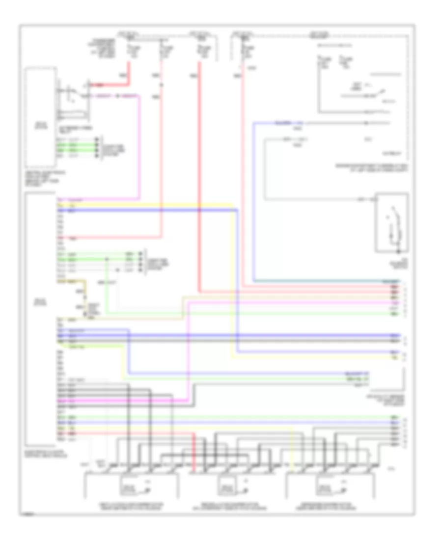
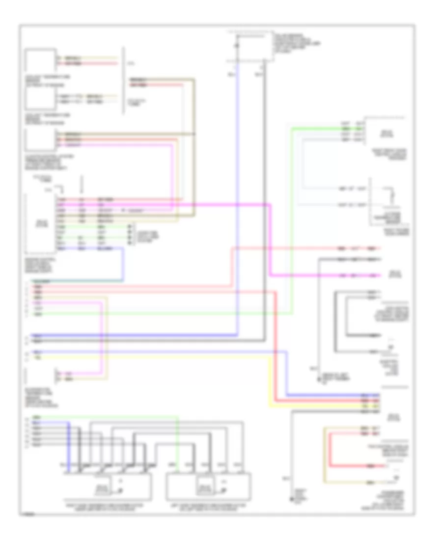
Автомтическая коробка Передач (АКПП) Полная привод (4WD) Блокировка Дифференциала
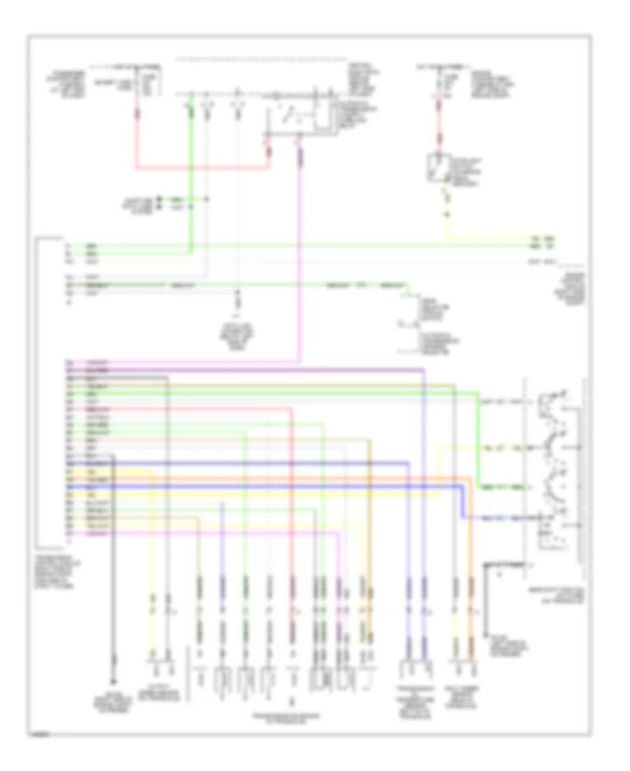
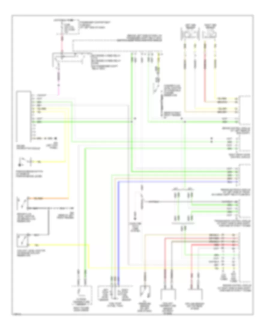
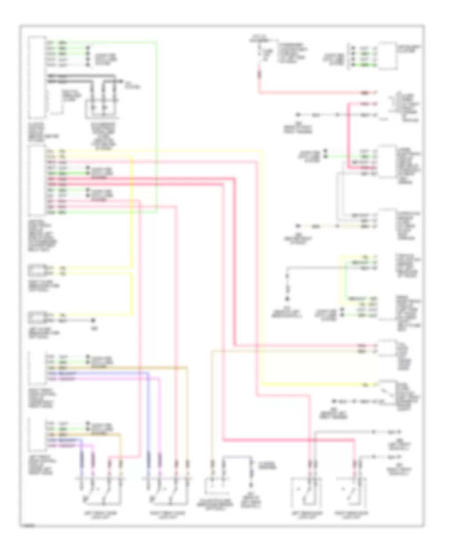
Электросхема автоматической коробки передач АКПП, AW55-50, AW50AWD для Volvo V70 2003
Электросхема автоматической коробки передач АКПП, AW55-50, AW50AWD для Volvo V70 2003 - Список элементов:
- (except xc90) (xc90)
- Automatic transmission program selector
- B13
- B26
- C24
- Central electrical module (behind left side of dash)
- Computer data lines system
- Data link connector (below left side of dash)
- Engine compartment fuse/relay box (left side of engine compt)
- Engine control module (right side of engine compt)
- Fuse b12 5a
- Fuse c21 c24 10a
- G31/93 (left side of engine compt, on fender)
- G31/94 (right side of engine compt, on fender)
- Gear selector module switch
- Gear shift position switches (on transaxle)
- Hot at all times
- Input speed sensor (rear of transaxle)
- Nca
- Otg
- Output speed sensor (on transaxle)
- Passenger compartment fuse box (at left end of dash)
- Red
- Sls
- Slsg
- Slt
- Sltg
- Slu
- Slug
- Sp1+
- Sp1-
- Sp2+
- Sp2-
- Stoplight switch (on brake pedal bracket)
- Transmission control module (right side of engine compt, forward of strut tower)
- Transmission oil temperature sensor (bottom of transaxle)
- Transmission solenoids (in transaxle)
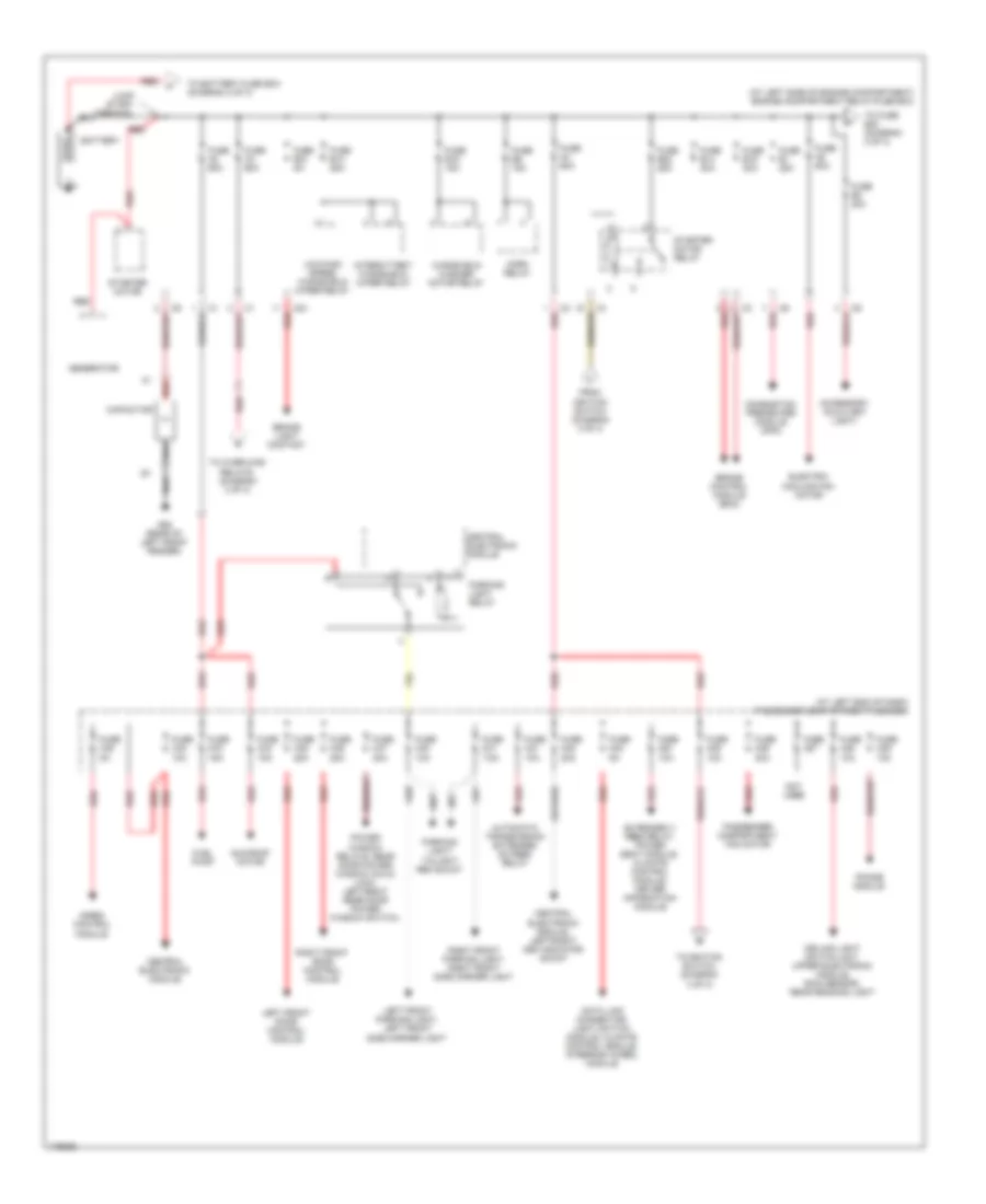
БЛОК ПРЕДОХРАНИТЕЛЕЙ И РЕЛЕ
Электросхема блока предохранителей и реле (1 из 3) для Volvo V70 2003
Электросхема блока предохранителей и реле (1 из 3) для Volvo V70 2003 - Список элементов:
- red
- (at left end of dash) passenger compartment fuse box
- (at left side of engine compartment) engine compartment relay/fuse box
- Accessory (auxiliary light)
- Automatic transmission extended d2 feed relay
- Battery
- Brake control module (bcm)
- Brake light contact
- C24
- Capacitor
- Ceiling light switch unit, upper electronic module, rain sensor, rear reading light
- Central electronic module
- Central electronic module, left/right cem indicator shunt
- Combustion preheater module (cpm)
- Data link connector, light switch module, climate control module, steering wheel module
- Electric cooling fan motor
- Extended x feed relay, power seat module, climate control module, driver information module
- From ignition switch (diagram 3 of 3)
- Fuel pump
- Fuse a2 60a
- Fuse a3 60a
- Fuse a4 60a
- Fuse a8 60a
- Fuse b1 25a
- Fuse b12 5a
- Fuse b13 25a
- Fuse b14 30a
- Fuse b16 15a
- Fuse b19 30a
- Fuse b2 20a
- Fuse b22 25a
- Fuse b9 15a
- Fuse c21 10a
- Fuse c22 20a
- Fuse c23 5a
- Fuse c24 10a
- Fuse c25 10a
- Fuse c26 30a
- Fuse c27
- Fuse c28 10a
- Fuse c29 10a
- Fuse c30 10a
- Fuse c31 7.5a
- Fuse c32 10a
- Fuse c33 15a
- Fuse c34 15a
- Fuse c35 25a
- Fuse c36 25a
- Fuse c37 30a
- Fuse c38 5a
- G93 (rear of left front fender)
- Generator
- Horn relay
- Intermittent windshield wiper relay
- Jump start terminal
- Left front door control module
- Left front parking light, left front side marker light
- Low/high speed windshield wiper relay
- Not used
- Parking light relay
- Parking light/ tailight rem shunt
- Passenger compartment fan motor
- Phone module
- Power window relays, rear door power window child lock, left/right rear door power window switch,
- Red
- Right front door control module
- Right front parking light, right front side marker light
- Siren control module
- Starter motor
- Starter motor relay
- Sun roof motor
- To battery fuse box (diagram 2 of 3)
- To fuse b23 (diagram 2 of 3)
- To ignition switch, (diagram 3 of 3)
- To overload relays, (diagram 3 of 3)
- Windshield washer motor relay
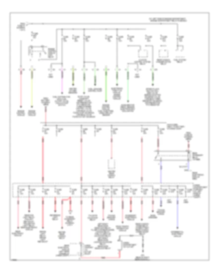
Электросхема блока предохранителей и реле (2 из 3) для Volvo V70 2003
Электросхема блока предохранителей и реле (2 из 3) для Volvo V70 2003 - Список элементов:
- (at left side of engine compartment)
- A red
- Accelerator pedal sensor, electrics box cooling fan
- Accessory electronic module
- Bass speaker
- Brake light relay, brake light rem shunt
- C20
- Cargo compart 12v outlet shunt
- Cargo compartment 12v outlet
- Cargo compartment fuse box (at left side of cargo compt)
- Climate control system relay
- D18
- Differential electronic module
- Electronic throttle module, engine control module
- Engine compartment relay/fuse box
- Engine control module
- Engine control module main relay
- Engine control module, fuel injectors, mass airflow sensor
- Evap valve, camshaft reset valve, air preheating ptc resistor, turbocharger control valve, variable valve timing inlet solenoid, variable valve timing outlet solenoid
- From battery (diagram 1 of 3)
- From f fuse a7 (diagram 1 of 3)
- From fuse d5 (diagram 2 of 3)
- Fuel distributor, dfco fuel cutoff valve, vacuum pump switch
- Fuel leakage control pump
- Fuel system relay
- Fuse b10 10a
- Fuse b11 20a
- Fuse b15 15a
- Fuse b23 5a
- Fuse b3 15a
- Fuse b4 20a
- Fuse b5 10a
- Fuse b6 15a
- Fuse b7 10a
- Fuse b8 10a
- Fuse d1 10a
- Fuse d10 10a
- Fuse d11 15a
- Fuse d12 15a
- Fuse d13 15a
- Fuse d15 20a
- Fuse d16
- Fuse d17 7.5a
- Fuse d18
- Fuse d2 10a
- Fuse d3 15a
- Fuse d4 10a
- Fuse d5 5a
- Fuse d6 10a
- Fuse d7 15a
- Fuse d8 20a
- Fuse d9 15a
- Fuse e1 40a
- Fuse e2 40a
- Fuse e3 40a
- Fuse e4
- Fuse e5 40a
- Fuse e6
- Fuse e7 40a
- G73 (rear of right rear door sill)
- Heated oxygen sensors
- Heated rear window relay
- Left/right rear door deadlock relay, filler flap/rear doors locking relay, fuel filler flap unlocking relay, left/right rear door locking/unlocking relay, rear door deadlock relay
- Main fuses (next to battery, in cargo comp)
- Not used
- Rear accessory relay (15 feed)
- Rear electrical module (left rear corner of cargo compt)
- Rear electronic module
- Rear electronic module (rem)
- Rear fog light relay, foglight rem shunt, trailer fog light relay, rear electronic module
- Rear window washer motor relay
- Rear window wiper relay, intermittent rear window wiper on/off relay
- Red
- Reversing light relay
- Road traffic information module
- Spark plug & ignition coil, egr valve, engine mounting solenoid valve, variable turbo geometry solenoid, air preheating ptc resistor
- Tailgate unlocking relay
- To rear accessory relay (diagram) 2 of 3
- Towing bracket wiring
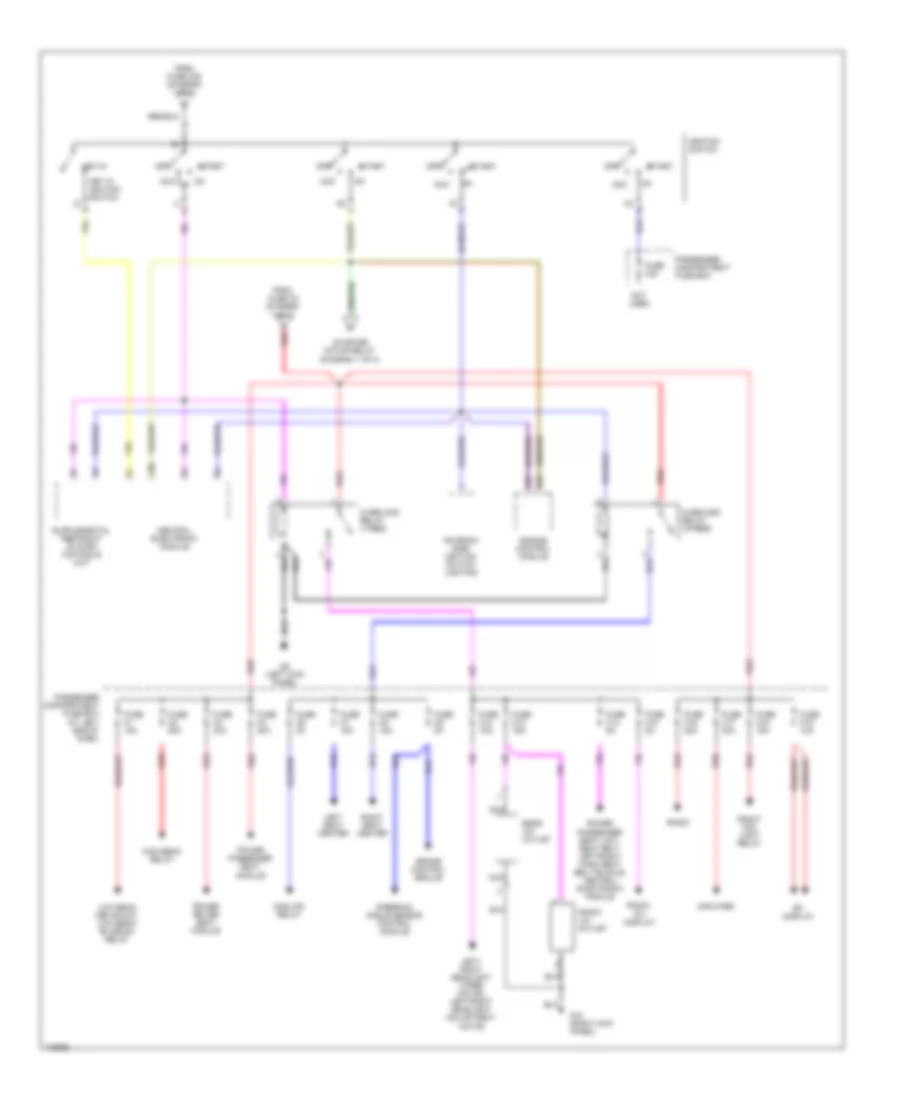
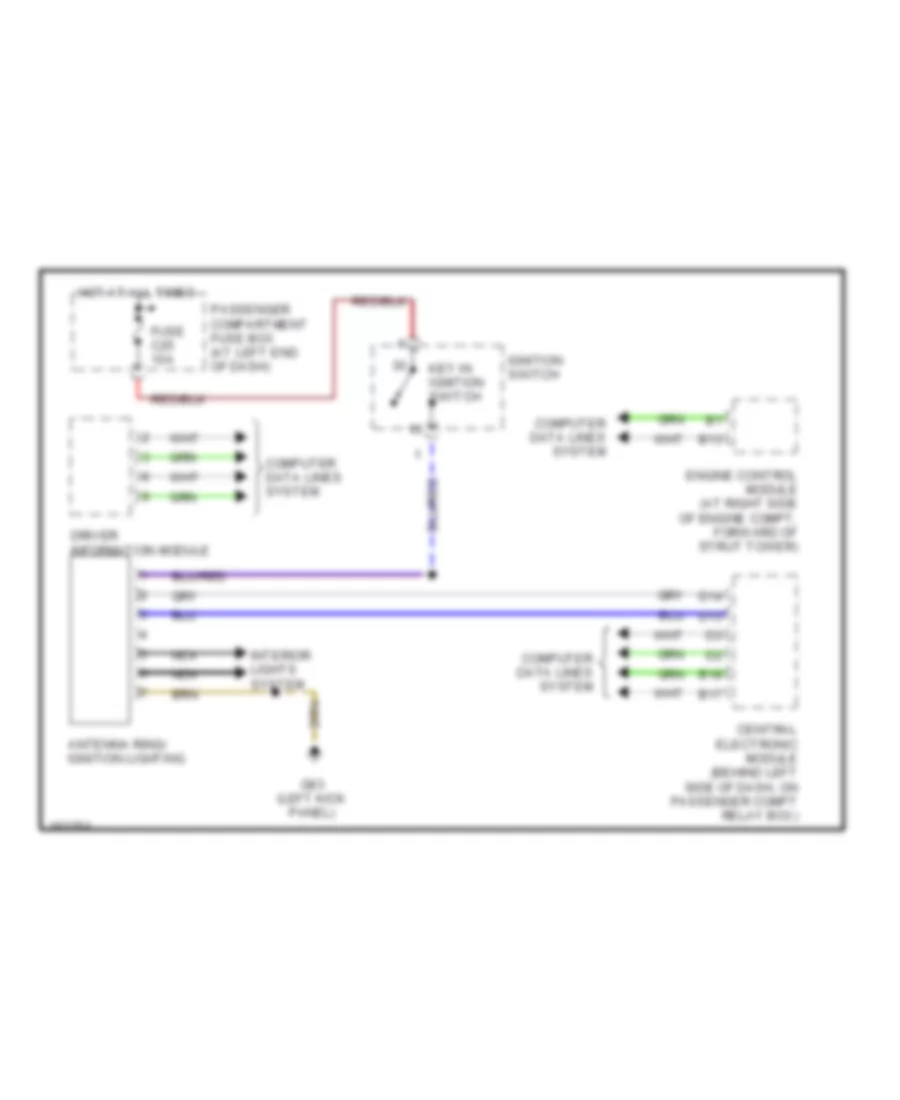
Электросхема блока предохранителей и реле (3 из 3) для Volvo V70 2003
Электросхема блока предохранителей и реле (3 из 3) для Volvo V70 2003 - Список элементов:
- 15i
- Acc
- Amplifier
- Antenna ring/ ignition switch lighting
- Brake control module
- Central electronic module
- Cng/lpg relay
- Engine control module
- From fuse a3 (diagram 1 of 3)
- From fuse c25 (diagram 1 of 3)
- Front 12v outlet
- Front fog light relay
- Fuse c1 15a
- Fuse c12 15a
- Fuse c13 15a
- Fuse c14 5a
- Fuse c15 5a
- Fuse c16 20a
- Fuse c17 30a
- Fuse c18 15a
- Fuse c19 10a
- Fuse c2 20a
- Fuse c20
- Fuse c3 30a
- Fuse c4 30a
- Fuse c6 5a
- Fuse c7 15a
- Fuse c8 15a
- Fuse c9 5a
- G10 (right kick panel)
- G6 (left kick panel)
- High beam relay
- Ignition switch
- Key in ignition switch
- Key-in
- Left seat heater
- Left/ right headlight wiper motor, left/right headlight adjustmemt motor
- Low beam cem shunt, low beam/ bi-xenon relay
- Nca
- Not used
- Off
- Overload relay 15-feed
- Overload relay x feed
- Passenger compartment fuse box
- Passenger compartment fuse box (at left end of dash)
- Power driver seat module
- Power passenger seat module
- Power passenger seat unit, seat belt left/right hand seat belt buckle, central electronic module
- Radio
- Radio, rti display
- Rear 12v outlet
- Red
- Right seat heater
- Rti display
- Start
- Starter motor relay (diagram 1 of 3)
- Steering angle sensor control module
БЛОКИ УПРАВЛЕНИЯ КУЗОВОМ
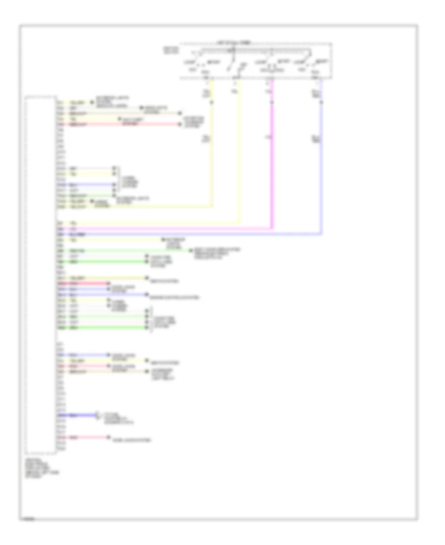
центральная электронная схема модуля (1 из 2) для Volvo V70 2003
центральная электронная схема модуля (1 из 2) для Volvo V70 2003 - Список элементов:
- 15a
- A10
- A11
- A12
- A13
- A14
- A15
- A16
- A17
- A18
- A19
- A20
- Acc
- Accessory auxiliary light relay
- Anti-theft system
- B10
- B11
- B12
- B13
- B14
- B15
- B16
- B17
- B18
- B19
- B20
- Body computer system (rear electronic module pin a4)
- C10
- C11
- C12
- C13
- C14
- C15
- C16
- C17
- C18
- C19
- C20
- Central electronic module (cem) (behind left side of dash)
- Computer data lines system
- Door locks system
- Engine controls system
- Exterior lights system
- Exterior lights system (back-up lamps)
- Headlights system
- Horns system
- Hot at all times
- Ignition switch
- Key in
- Lock
- Pnk
- Run
- Seats system
- Start
- Starting/ charging system
- To fuel pump relay (diagram 2 of 2)
- Wiper/ washer system
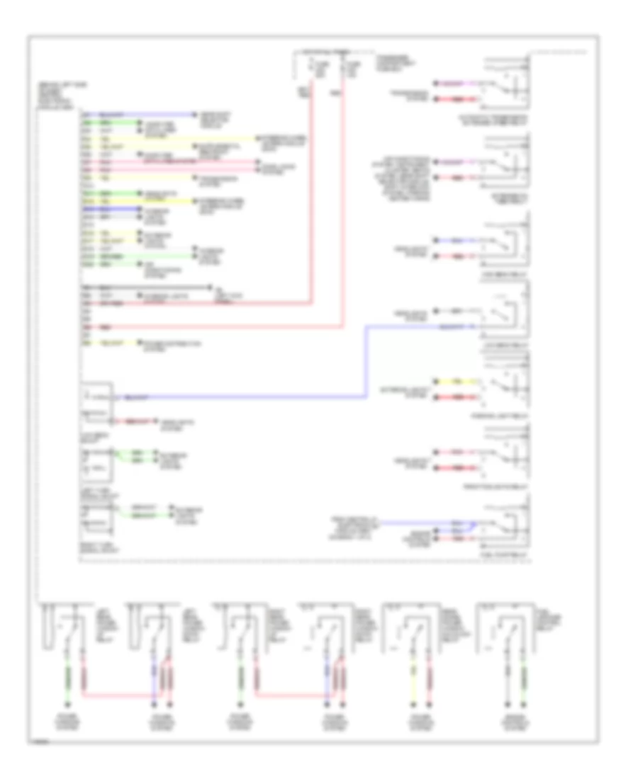
центральная электронная схема модуля (2 из 2) для Volvo V70 2003
центральная электронная схема модуля (2 из 2) для Volvo V70 2003 - Список элементов:
- (behind left side of dash) central electronic module (cem)
- Air conditioning system
- Air conditioning system, instrument cluster, seats system, gear shift selector module, shift interlock system, parking heater wiring
- Automatic transmission extended xfeed relay
- Computer data lines system
- D10
- D11
- D12
- D13
- D14
- D15
- D16
- D17
- D18
- D19
- D20
- Door locks system
- Engine controls system
- Extended d2 feed realy
- Exterior lights system
- From central electronic a module (cem) (diagram 1 of 2)
- Front foglights relay
- Fuel leakage control relay
- Fuel pump relay
- Fuse c22 20a
- Fuse c32 10a
- G6 (left kick panel)
- Gear shift selector module
- Headlights system
- High beam relay
- Hot at all times
- Interior lights system
- Left rear power window down relay
- Left rear power window up relay
- Left turn signal shunt
- Low beam relay
- Low beam shunt
- Parking light relay
- Passenger compartment fuse box
- Pnk
- Power distribution system
- Power windows system
- Rear doors power window childlock relay
- Red
- Right rear power window down relay
- Right rear power window up relay
- Right turn signal shunt
- Steering wheel levers module (swm)
- Transmission system
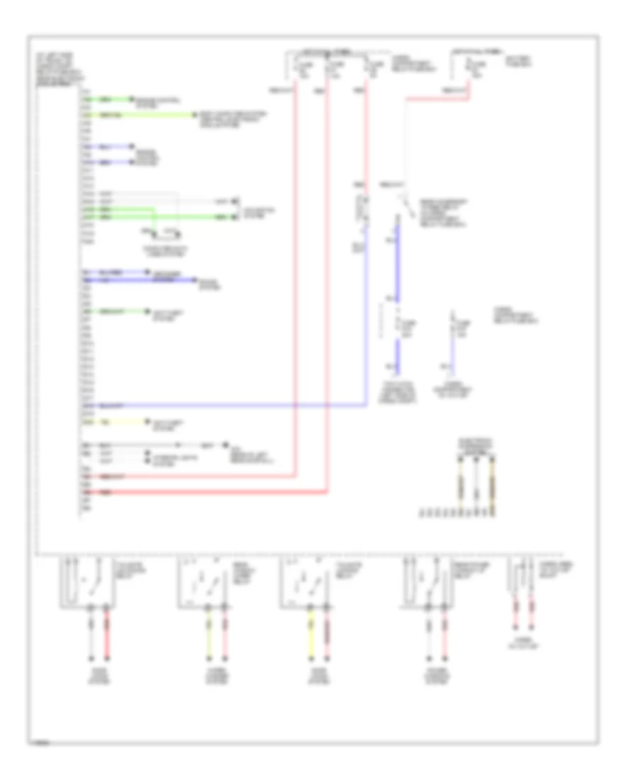
задняя электронная схема модуля (1 из 2) для Volvo V70 2003
задняя электронная схема модуля (1 из 2) для Volvo V70 2003 - Список элементов:
- (at left side of trunk, on cargo compt relay/fuse box) rear electronic module (rem)
- 12v outlet
- A10
- A11
- A12
- A13
- A14
- A15
- A16
- A17
- A18
- A19
- A20
- Anti-theft system
- B10
- Battery fuse box
- Body computer system (central electronic module pin b6)
- Cargo
- Cargo area 12v outlet shunt
- Cargo compartment 12v outlet
- Cargo compartment relay/fuse box
- Computer data lines system
- D10
- D11
- D12
- D13
- D14
- D15
- D16
- D17
- D18
- D19
- D20
- Defogger system
- Door locks system
- Electronic suspension system
- Engine control system
- Fuse d1 10a
- Fuse d15 20a
- Fuse d16 15a
- Fuse d2 10a
- Fuse d5 5a
- Fuse e1 40a
- G72 (rear of left rear door sill)
- Hot at all times
- Interior lights system
- Navigation system
- Power windows system
- Rear accessory 15 feed relay (in cargo compartment relay fuse box)
- Rear power window up relay
- Rear window wiper relay
- Red
- Sound system
- Tailgate locking relay
- Tailgate unlocking relay
- Tow hitch connector (left side of cargo compt)
- Wiper/ washer system
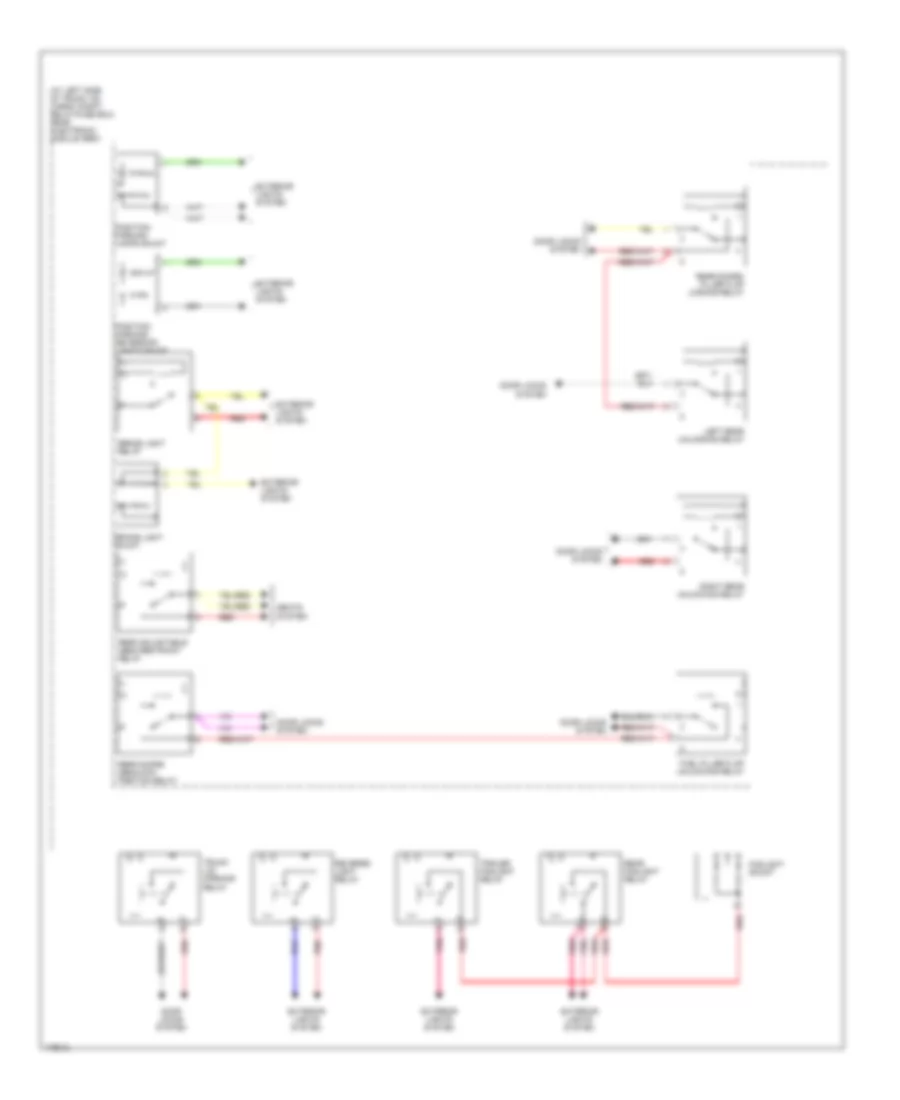
задняя электронная схема модуля (2 из 2) для Volvo V70 2003
задняя электронная схема модуля (2 из 2) для Volvo V70 2003 - Список элементов:
- (at left side of trunk, on cargo compt relay/fuse box) rear electronic module (rem)
- Brake light relay
- Brake light shunt
- Door locks system
- Exterior lights system
- Foglight shunt
- Fuel filler flap unlocking relay
- Left rear unlocking relay
- Pnk
- Position/ parking lamps shunt
- Position/ parking/ reversing lights shunt
- Rear adjustable head restraint relay
- Rear doors deadlock position relay
- Rear doors/ filler flap locking relay
- Rear foglight relay
- Red
- Reverse light relay
- Right rear unlocking relay
- Seats system
- Trailer foglight relay
- Trunk lid/ opening relay
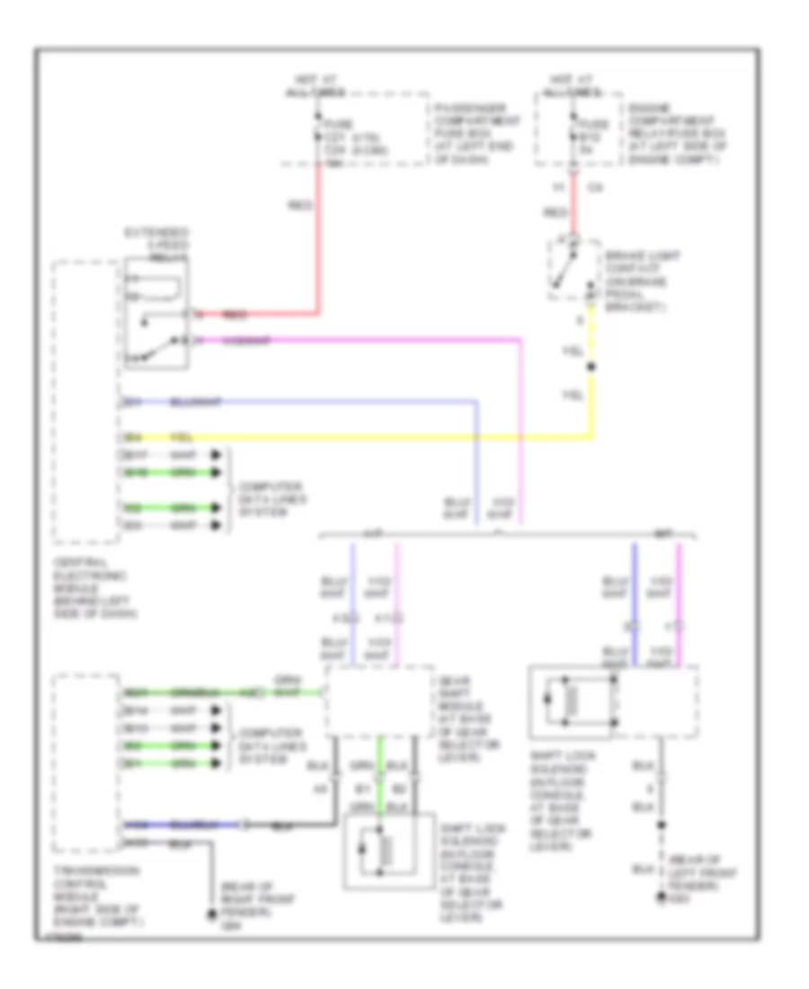
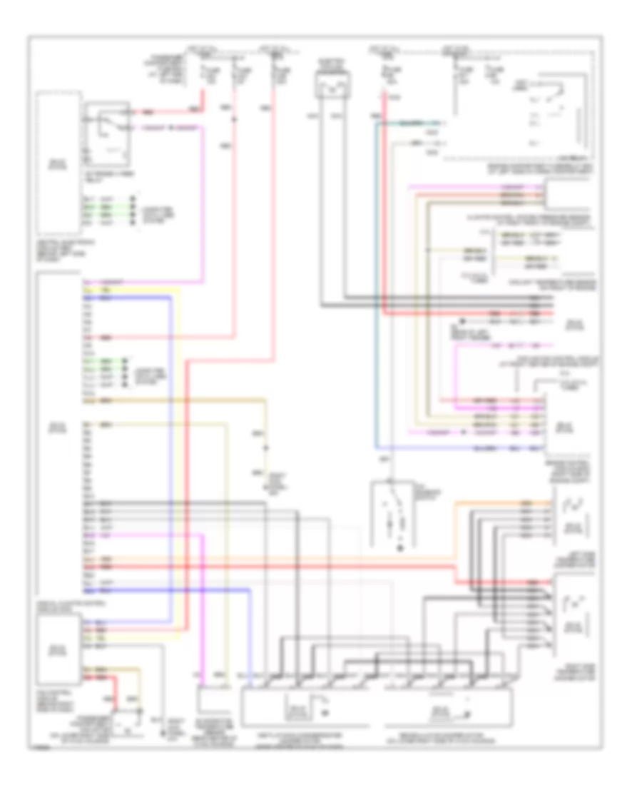
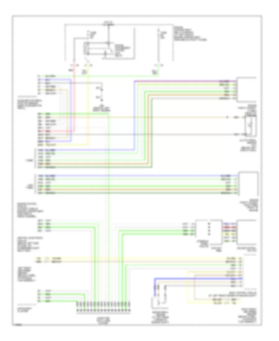
БЛОКИРОВКИ СЕЛЕКТОРА СТОЯНОЧНЫЙ ТОРМОЗ
Электросхема блокировки селектора для Volvo V70 2003
Электросхема блокировки селектора для Volvo V70 2003 - Список элементов:
- (in floor console, at base of gear selector lever)
- (rear of left front fender) g93
- (rear of right front fender) g94
- (v70) (xc90)
- A/t
- A53
- A54
- B13
- B14
- B17
- B18
- B21
- Brake light contact (on brake pedal bracket)
- Central electronic module (behind left side of dash)
- Computer data lines system
- Engine compartment relay/fuse box (at left side of engine compt)
- Extended x-feed relay
- Fuse b12 5a
- Fuse c21 c24 10a
- Gear shift module (at base of gear selector lever)
- Hot at all times
- M/t
- Passenger compartment fuse box (at left end of dash)
- Red
- Shift lock solenoid
- Shift lock solenoid (in floor console, at base of gear selector lever)
- Transmission control module (right side of engine compt)
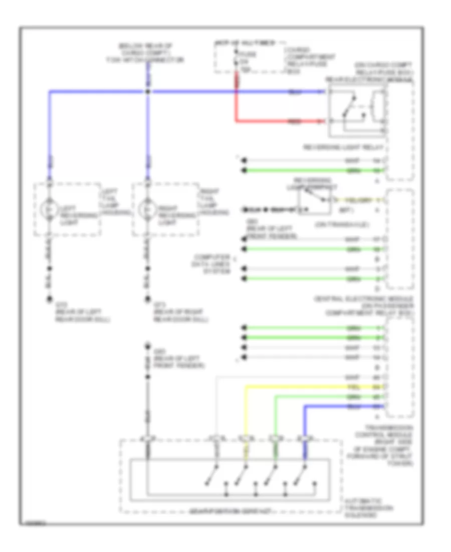
ВНЕШНЕЕ ОСВЕЩЕНИЕ
Электросхема заднего хода для Volvo V70 2003
Электросхема заднего хода для Volvo V70 2003 - Список элементов:
- (below rear of cargo compt) tow hitch connector
- (m/t)
- (on cargo compt relay/fuse box) rear electronic module
- (on transaxle)
- Automatic transmission solenoid
- Cargo compartment relay/fuse box
- Central electronic module (on passenger compartment relay box)
- Computer data lines system
- Fuse d4 10a
- G72 (rear of left rear door sill)
- G73 (rear of right rear door sill)
- G93 (rear of left front fender)
- Gear position contact
- Hot at all times
- Left reversing light
- Left tail lamp housing
- Nca
- Red
- Reversing light contact
- Reversing light relay
- Right reversing light
- Right tail lamp housing
- Transmission control module (right side of engine compt, forward of strut tower)
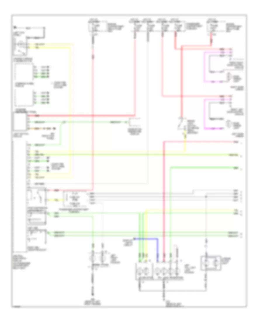
Электросхема внешнего освещения (1 из 2) для Volvo V70 2003
Электросхема внешнего освещения (1 из 2) для Volvo V70 2003 - Список элементов:
- (left kick panel)
- B/u
- Back-up lights circuit
- Brake light switch (on brake pedal bracket)
- C24
- Central electronic module (on passenger compartment relay box)
- Combined instrument panel
- Combustion preheater module
- Computer data lines system
- Door mirror light
- Engine compartment relay/fuse box
- Fog
- Front left door control module
- Front right door control module
- Fuse a2 60a
- Fuse b12 5a
- Fuse c22 20a
- Fuse c23 5a
- Fuse c30 10a
- Fuse c31 7.5a
- Fuse c35 25a
- Fuse c36 25a
- G72 (rear of left rear door sill)
- G84 (right kick panel)
- G93 (rear of left front fender)
- Hazard warning flasher switch
- Hot at all times
- Left cem indicator shunt
- Left door mirror
- Left front lamp housing
- Left tail light lamp housing
- License plate light
- Light switch module
- Park
- Passenger compartment fuse box
- Pnk
- Position/parking lights relay
- Red
- Right cem indicator shunt
- Right door mirror
- Steering wheel module
- Stop
- Turn
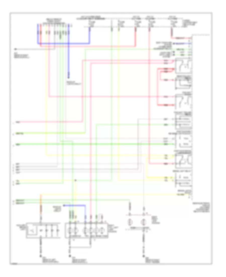
Электросхема внешнего освещения (2 из 2) для Volvo V70 2003
Электросхема внешнего освещения (2 из 2) для Volvo V70 2003 - Список элементов:
- (below rear of cargo compt) tow hitch connector
- Auxiliary brake light
- B/u
- Back-up lights circuit
- Body computer system (15 feed rear accessory relay)
- Brake light relay
- Brake lights shunt
- Cargo compartment relay/fuse box
- Computer data lines system
- Fog
- Foglight shunt
- Foglight trailer relay
- Fuse d14 7.5a
- Fuse d15 20a
- Fuse d2 10a
- Fuse d3 15a
- Fuse d9 15a
- G72 (rear of left rear door seal)
- G73 (rear of right rear door sill)
- G94 (rear of right front fender)
- Hot at all times
- Hot w/15 feed rear accessory relay energized
- Park
- Pnk
- Position/park/ reverse lights shunt
- Position/parking lights shunt
- Rear electronic module (on cargo compartment relay/fuse box)
- Rear foglight relay
- Red
- Right front lamp housing
- Right tail light lamp housing
- Stop
- Turn
ВНУТРЕННЕЕ ОСВЕЩЕНИЕ
Электросхема подсветки для Volvo V70 2003
Электросхема подсветки для Volvo V70 2003 - Список элементов:
- (center front of roof)
- (left front door sill)
- (left kick panel)
- (left rear of passenger compt)
- (right front door sill)
- A10
- Antenna ring/ ignition switch light
- B10
- B12
- B17
- B18
- C18
- Cargo area compartment/ dome light
- Central electronic module (on passenger compt relay box)
- Computer data lines system
- D18
- D19
- Dome light control module
- Fuse c28 10a
- Fuse c32 10a
- Fuse c35 25a
- Fuse c36 25a
- G10 (right kick panel)
- G47
- G6 (left kick panel)
- G66
- G66 (left front door sill)
- G67
- G67 (right front door sill)
- G98
- G98 (center front of roof)
- Glass breakage sensor
- Glove compartment light
- Hot at all times
- Left door mirror light
- Left front door control module
- Left front door lock unit
- Left front entry light
- Left power door mirror
- Left rear door lock unit
- Left vanity mirror light
- Passenger compartment fuse box
- Pnk
- Rear reading lights
- Red
- Right door mirror light
- Right front door control module
- Right front door lock unit
- Right front entry light
- Right power door mirror
- Right rear door lock unit
- Right vanity mirror light
- Steering wheel module
- Tailgate lock unit
- Upper electronic module (above center of windshield, on rearview mirror)
Электросхема подсветки приборов для Volvo V70 2003
Электросхема подсветки приборов для Volvo V70 2003 - Список элементов:
- (not used)
- (right kick panel)
- (v70) (xc90)
- (v70) a7
- (xc90) d2
- A/c climate control switch
- A11
- A12
- A13
- A14
- A16
- A18
- Audio/mobile phone switch
- Auto
- Auto climate control switch
- Auxiliary light switch
- B17
- B18
- Central electronic module (on passenger compt relay box)
- Climate control lighting
- Climate control module
- Compartment fan potentiometer lighting
- Computer data lines system
- Contact reel
- Courtesy light switch module
- Cruise control switch
- Defr
- Defroster climate control switch
- Extended x feed relay (v70) extended di feed relay (xc90)
- Fan switch
- Floor
- Floor climate control switch
- Front cigarette lighter 12v outlet
- Fuse c23 c22 5a
- Fuse c24 c21 10a
- Fuse c32 c27 10a
- Fuse c37 c7 30a
- G66 (left front door sill)
- G67 (right front door sill)
- G84
- Heated rear window/door mirrors switch
- Heated rear window/mirrors/ front seats lighting switches
- Hot at all times
- Instrument panel
- Left heated control lighting
- Left rear door light switch
- Left seat heated switch
- Left side temperature switch
- Light control module switch
- Max defroster switch
- Nca
- Passenger compartment fuse box
- Power child lock switch (pcl)
- Power sun roof switch
- Radio
- Rear adjustable head restraint
- Rear door power window child lock relay
- Rec
- Recirculation a/c light
- Recirculation switch
- Red
- Reduced alarm switch
- Retractable door mirrors switch
- Right heated control lighting
- Right rear door light switch
- Right seat heated switch
- Right side temperature switch
- Spin control switch
- Steering wheel module (on side of passenger comptment relay box)
- Sunroof control module
- Trunk lid/ tailgate private lock switch
- Upper electronic module (above center of windshield, on rearview mirror)
- Vent
- Ventilation climate control switch
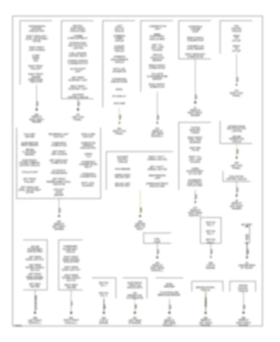
ЗАЗЕМЛЕНИЕ ПОДКЛЮЧЕНИЕ МАССЫ
Электросхема подключение массы заземления для Volvo V70 2003
Электросхема подключение массы заземления для Volvo V70 2003 - Список элементов:
- 15-feed overload relay
- Accelerator pedal sensor
- Accessory electronic module (aem)
- Air preheating ptc resistor
- Alarm siren scm
- Amplifier
- Antenna ring/ ignition switch lighting
- Automatic transmission
- Auxiliary heater
- Bass speaker
- Battery
- Brake control module
- Brake fluid level sensor
- Cargo compartment 12v outlet
- Cargo compt ceiling light
- Ceiling light switch unit
- Central electronic module (cem)
- Climate control module
- Combustion preheat module (cpm)
- Coolant level sensor
- Cooling fan control module
- Data link connector
- Driver information module
- Driver power seat module (psm)
- Electronic power steering control module
- Electronic throttle module (etm)
- Engine control module
- Fan control module
- Front 12v outlet
- Fuel leakage control relay
- Fuel pump
- G1 (rear of right front fender)
- G10 (right kick panel)
- G2 (rear of left front fender)
- G3 (center rear of trunk)
- G47 (rear of left rear door sill)
- G48 (rear of right rear door sill)
- G6 (left kick panel)
- G66 (left front door sill)
- G67 (right front door sill)
- G72 (rear of left rear door sill)
- G73 (rear of right rear door sill)
- G83 (left kick panel)
- G84 (right kick panel)
- G88 (top of engine)
- G89 (top of engine)
- G91 (left rear of engine)
- G93 (rear of left front fender)
- G94 (rear of right front fender)
- G95 (rear of left front fender)
- G96 (rear of right front fender)
- G98 (center front of roof)
- Gas tank valve
- Glove compt light
- Hazard warning flasher switch
- Hood alarm contact
- Horns 1 & 2
- Ignition coil 1
- Ignition coil 2
- Ignition coil 3
- Ignition coil 4
- Ignition coil 5
- Integrated mobile phone
- Left front courtesy light
- Left front door control module (ddm)
- Left front fender directional indicator
- Left front foglight
- Left front lamp housing
- Left headlamp level adjustment motor
- Left headlight wiper motor
- Left rear door lock unit
- Left rear power window switch
- Left seat heater
- Left tail light lamp housing
- Left vanity mirror lighting
- License plate light
- Light switch module
- Passenger power seat module
- Radio
- Rain sensor
- Rear 12v outlet
- Rear electronic module (rem)
- Rear reading lamp
- Rear window washer pump
- Rear window wiper motor
- Reversing light contact
- Right front courtesy light
- Right front door control module (pdm)
- Right front fender directional indicator
- Right front foglight
- Right front fuel tank solenoid
- Right front lamp housing
- Right headlight level adjustment motor
- Right headlight wiper motor
- Right rear door lock unit
- Right rear power window switch
- Right seat heater
- Right tail light lamp housing
- Right vanity mirror lighting
- Road traffic information
- Rti display
- Shift lock solenoid
- Steering angle sensor module
- Steering wheel module
- Sun roof control module
- Tail gate glass breakage sensor
- Tailgate glass breakage sensor
- Towing bracket wiring
- Transmission control module (tcm)
- Upper electronic module (uem)
- Vacuum pump
- Vehicle inclination sensor
- Washer fluid level sensor
- Windshield washer motor relay
- Windshield washer pump
- Windshield wiper motor
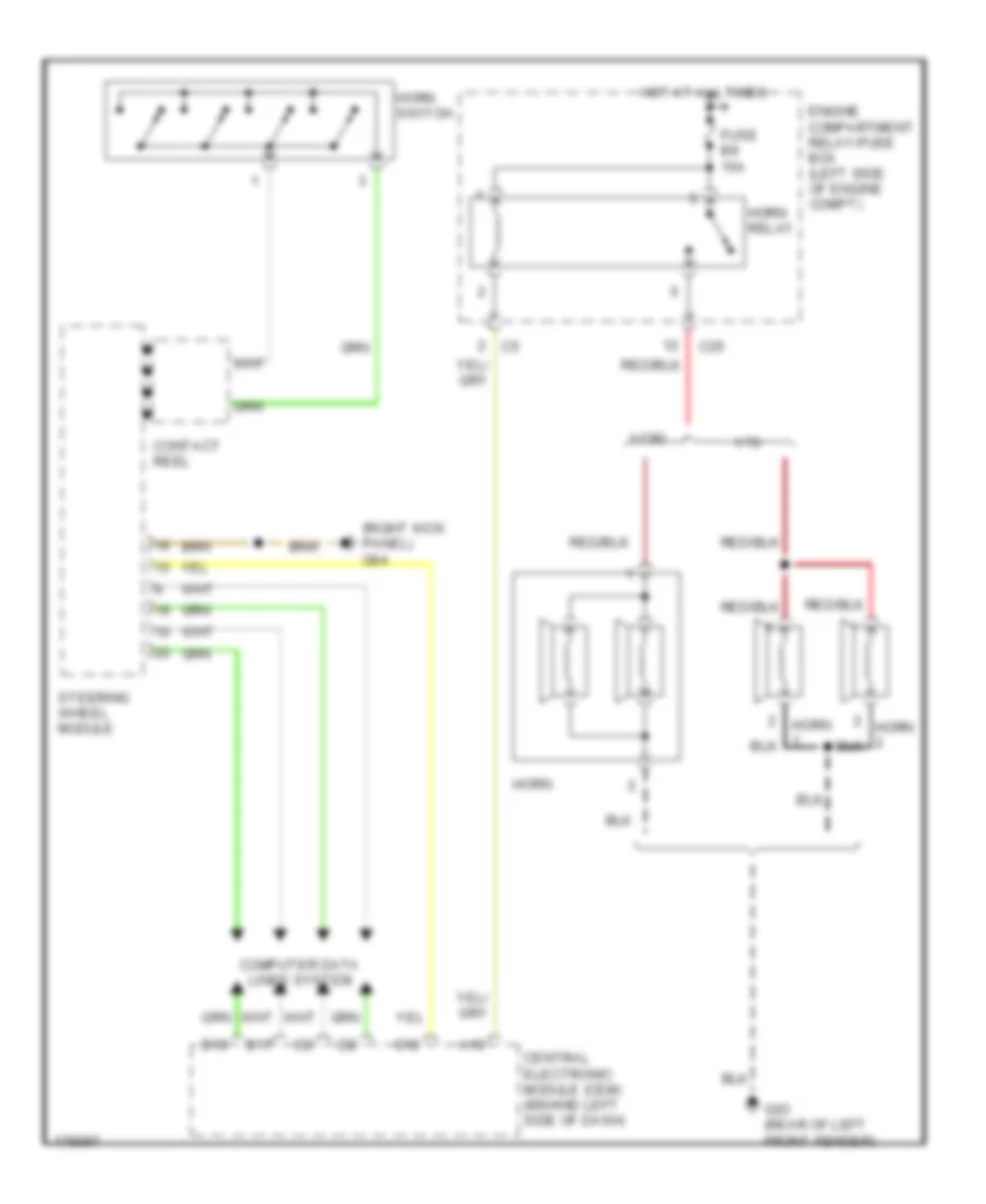
Звуковой сигнал Гудок
Электросхема звукового сигнал Гудка для Volvo V70 2003
Электросхема звукового сигнал Гудка для Volvo V70 2003 - Список элементов:
- (right kick panel) g84
- A19
- B17
- B18
- C25
- Central electronic module (cem) (behind left side of dash)
- Computer data lines system
- Contact reel
- D12
- Engine compartment relay/fuse box (left side of engine compt)
- Fuse b9 15a
- G93 (rear of left front fender)
- Horn
- Horn relay
- Horn switch
- Hot at all times
- Steering wheel module
- V70
- Xc90
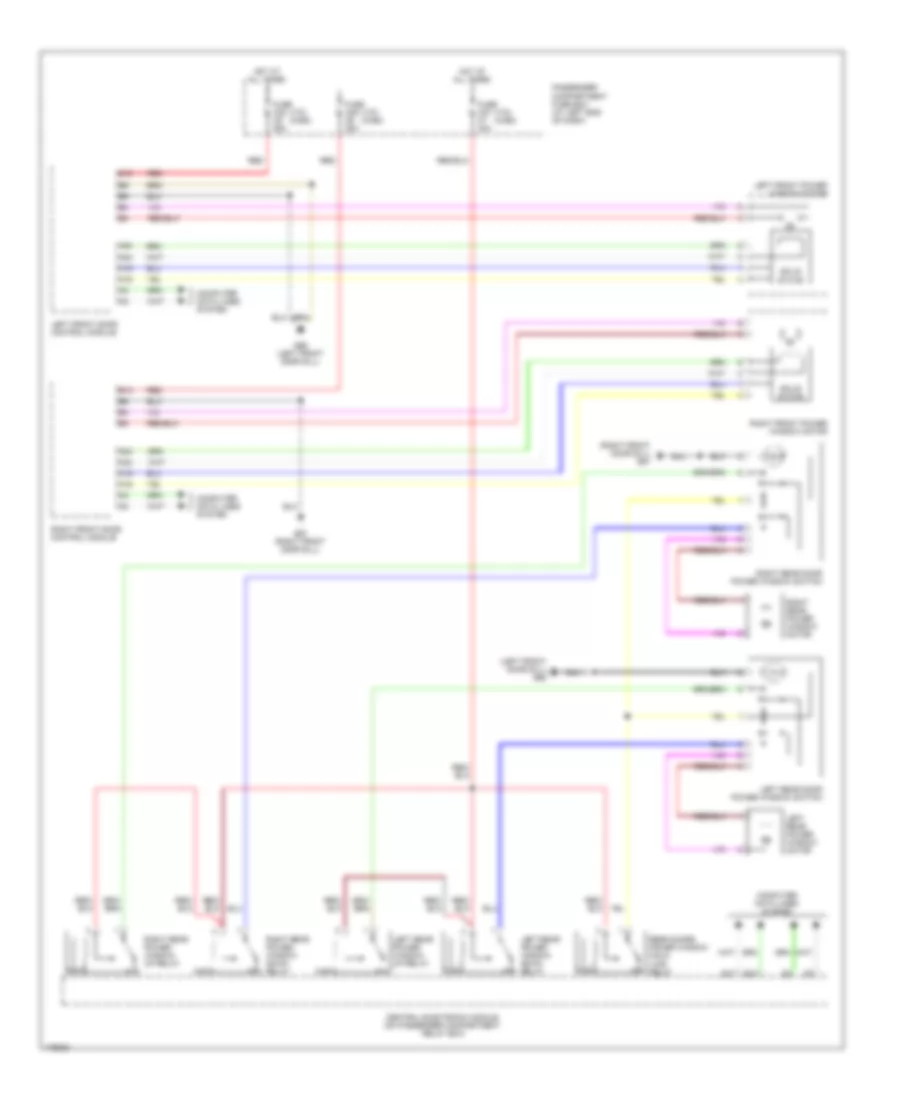
Магнитола Мультимедия
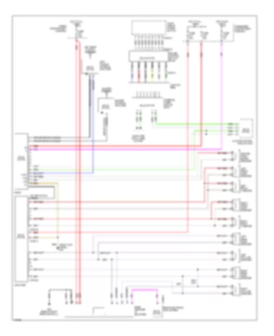
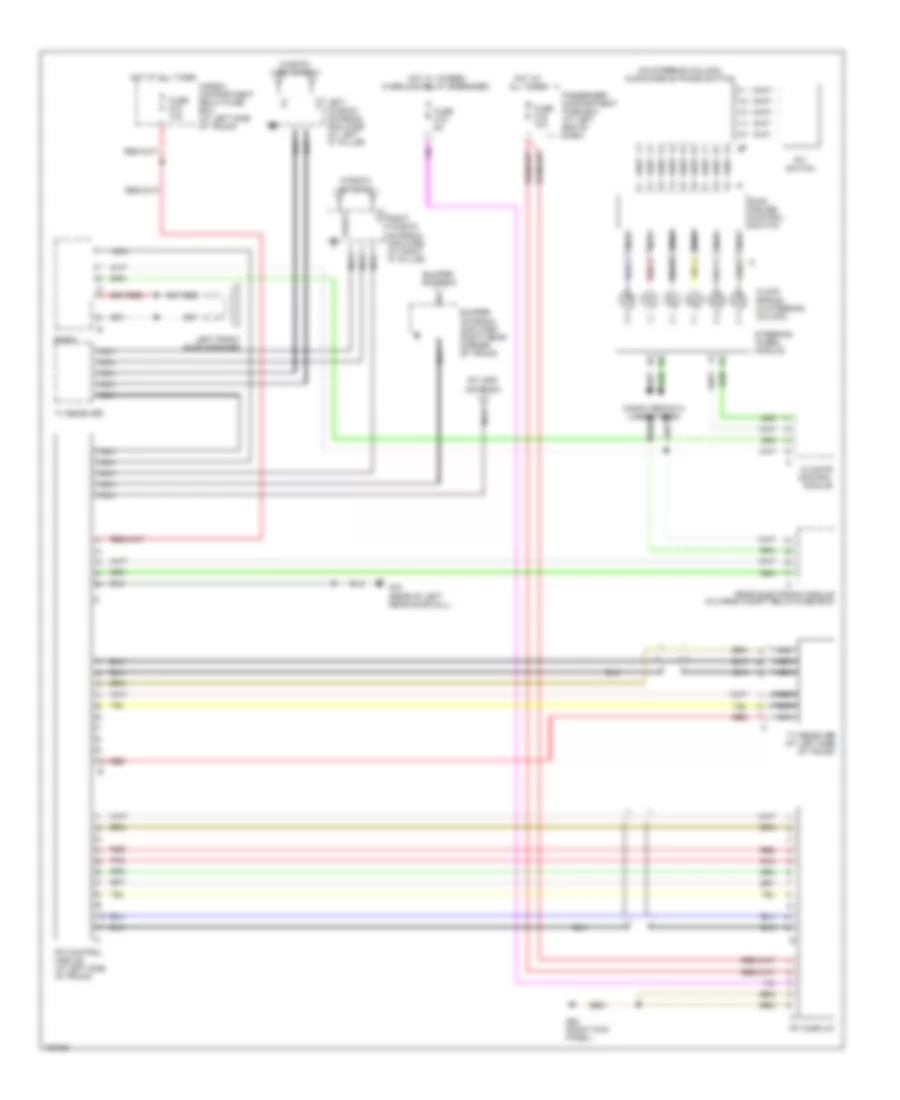
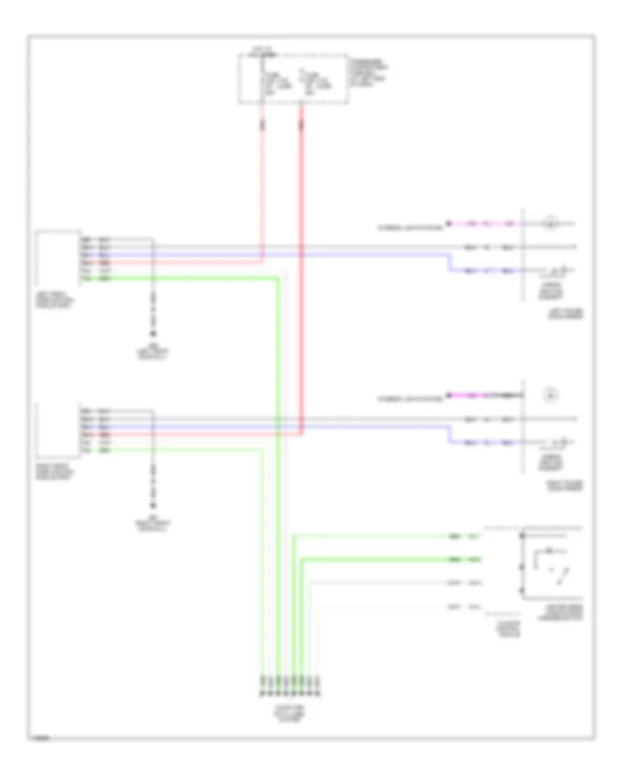
Электросхема магнитолы, С усилитель для Volvo V70 2003
Электросхема магнитолы, С усилитель для Volvo V70 2003 - Список элементов:
- (right kick panel) g84
- + ant
- + cs
- - cs
- Amplifier
- Audio mobile phone switch
- Bass speaker (if equipped)
- Bumper antenna
- Bumper antenna amplifier
- Cargo compartment fuse box
- Center dash- board speaker
- Climate control module (ccm)
- Computer data lines system
- Conn a
- Conn b
- Conn d
- Contact reel
- Cruise control switch (sws)
- Din (or coaxial cable)
- Din or (coaxial cable)
- Fuse c15 5a
- Fuse c16 20a
- Fuse c17 30a
- Fuse d13 15a
- G48 (rear of right rear door sill)
- Hot at all times
- Hot in acc or on
- Left d-pillar speaker
- Left front door speaker
- Left front tweeter
- Left rear door speaker
- Left rear window amplifier
- Left window antenna amplifier
- Nca
- Passenger compartment fuse box
- Radio
- Rear electronic module (rem)
- Red
- Right d-pillar speaker
- Right front door speaker
- Right front tweeter
- Right rear door speaker
- Solid state
- Steering wheel module (swm)
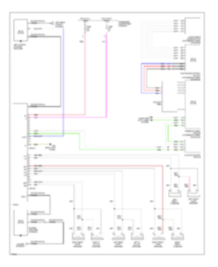
Электросхема магнитолы, без Усилитель для Volvo V70 2003
Электросхема магнитолы, без Усилитель для Volvo V70 2003 - Список элементов:
- + ant
- +lf
- +lr
- +rf
- +rr
- -lf
- -lr
- -rf
- -rr
- A11
- A12
- A13
- A14
- Audio mobile phone switch (w/steering wheel controls)
- Bumper amplifier antenna
- Bumper antenna
- Climate control module
- Computer data lines system
- Conn a
- Conn b
- Contact reel
- Din (or coaxial cable)
- Fuse c15 5a
- Fuse c16 20a
- G84 (right kick panel)
- Hot at all times
- Hot in acc or on
- Input
- Left d pillar speaker
- Left front door speaker
- Left front tweeter
- Left rear door speaker
- Left rear window antenna
- Left window antenna amplifier
- Nca
- Passenger compartment fuse box
- Radio
- Red
- Right d pillar speaker
- Right front door speaker
- Right front tweeter
- Right rear door speaker
- Solid state
- Steering wheel module (w/steering wheel controls)
- Sws cruise control switch (w/steering wheel controls)
Навигация GPS Парктроники
Электросхема навигации GPS для Volvo V70 2003
Электросхема навигации GPS для Volvo V70 2003 - Список элементов:
- (on steering column) audio/mobile phone switch
- Bumper antenna
- Bumper antenna amplifier (right rear corner of trunk)
- Cargo/ compartment relay/fuse box (at left side of trunk)
- Climate control module
- Clock spring (in steering column)
- Computer data lines system
- Fuse c15 5a
- Fuse c19 10a
- Fuse d10 10a
- G72 (rear of left rear door sill)
- G84 (right kick panel)
- Hot at all times
- Hot w/ 15-feed overload relay energized
- Left front door speaker
- Left window antenna amplifier (at left "c" pillar)
- Nca
- Passenger compartment fuse box (at left end of dash)
- Pnk
- Radio
- Rear electronic module (in cargo compt relay/fuse box)
- Red
- Right window antenna amplifier (at right "c" pillar)
- Rti control module (at left side of trunk)
- Rti display
- Rti gps antenna
- Rti switch
- Rti/tv
- Steering wheel module
- Sws cruise control switch
- Tv receiver
- Tv receiver (at left side of trunk)
- Window antenna
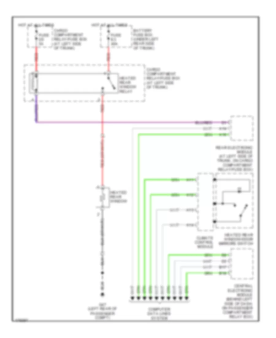
Подогрев стекол и зеркал
Электросхема подогрева зеркал заднего вида для Volvo V70 2003
Электросхема подогрева зеркал заднего вида для Volvo V70 2003 - Список элементов:
- (v70) (xc90)
- A11
- A12
- A13
- A14
- B10
- B11
- B12
- Climate control module
- Computer data lines system
- Fuse c35 c5 25a
- Fuse c36 c6 25a
- G66 (left front door sill)
- G67 (right front door sill)
- Heated rear window/door mirrors switch
- Hot at all times
- Interior lights system
- Left front door control module (ddm)
- Left power door mirror
- Mirror heating element
- Nca
- Passenger compartment fuse box (at left end of dash)
- Red
- Right front door control module (pdm)
- Right power door mirror
Электросхема заднего стекла для Volvo V70 2003
Электросхема заднего стекла для Volvo V70 2003 - Список элементов:
- A11
- A12
- A13
- A14
- A16
- B17
- B18
- Battery fuse box (under left rear side of trunk)
- Cargo compartment relay/fuse box (at left side of trunk)
- Central electronic module (behind left side of dash, on passenger compartment relay box)
- Climate control module
- Computer data lines system
- Fuse d5 5a
- Fuse e3 40a
- G47 (left rear of passenger compt)
- Heated rear window
- Heated rear window relay
- Heated rear window/door mirrors switch
- Hot at all times
- Rear electronic module (at left side of trunk, on cargo compartment relay/fuse box)
- Red
ПОДУШКИ БЕЗОПАСНОСТИ AIR BAG
Электросхема подушек безопасности SRS AirBag (1 из 2) для Volvo V70 2003
Электросхема подушек безопасности SRS AirBag (1 из 2) для Volvo V70 2003 - Список элементов:
- (near rear of left front door) left-hand front side impact sensor
- Acc
- B19
- B20
- Central electronic module (cem) (behind left side of dash, on passenger compartment relay box)
- Computer data lines system
- Contact reel
- Data link connector (partial) (below left side of dash)
- Driver information module (dim)
- Driver side air bag igniter
- Driver side air bag igniter step 2
- Hot at all times
- Ignition switch
- Left front seat belt tensioner igniter
- Left front side air bag igniter
- Left rear belt tensioner igniter
- Left-hand rear side impact sensor (near rear of left rear door)
- Nca
- Off
- Passenger side air bag igniter
- Passenger side air bag stage 2 igniter
- Solid state
- Start
- W/ telephone
- W/o telephone
Электросхема подушек безопасности SRS AirBag (2 из 2) для Volvo V70 2003
Электросхема подушек безопасности SRS AirBag (2 из 2) для Volvo V70 2003 - Список элементов:
- (near rear of right front door) right-hand front side impact sensor
- Center rear seat belt tensioner igniter
- Computer data lines system
- Left hand inflatable curtain igniter
- Left seat belt latch switch
- Nca
- Right front seat belt tensioner igniter
- Right front side air bag igniter
- Right hand inflatable curtain igniter
- Right rear belt tensioner igniter
- Right seat belt latch switch
- Right-hand rear side impact sensor (near rear of right rear door)
- Solid state
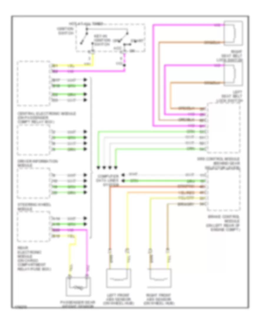
ПРЕДУПРЕЖДАЮЩИЕ СИСТЕМЫ
Электросхема предупреждающей системы для Volvo V70 2003
Электросхема предупреждающей системы для Volvo V70 2003 - Список элементов:
- A14
- A16
- Acc x
- B17
- B18
- B19
- B20
- Brake control module (on left rear of engine compt)
- Central electronic module (on passenger compt relay box)
- Computer data lines system
- Driver information module
- Hot at all times
- Ignition switch
- Key-in ignition switch
- Left front abs sensor (on wheel hub)
- Left seat belt lock switch
- Off
- Passenger sear weight sensor
- Rear electronic module (on cargo compartment relay/fuse box)
- Right front abs sensor (on wheel hub)
- Right seat belt lock switch
- Srs control module (behind gear selector lever)
- Start
- Steering wheel module
ПРИБОРНАЯ ПАНЕЛЬ
Электросхема панели приборов для Volvo V70 2003
Электросхема панели приборов для Volvo V70 2003 - Список элементов:
- (behind left side of dash, on passenger compt relay box) central electronic control module
- (on passenger compt relay box)
- (rear of right front fender) g1
- (v70) (xc90)
- 2.4l non- turbo
- A/t
- Brake control module (at left rear of eng compt)
- Brake fluid level monitor (on brake fluid reservoir)
- Computer data lines system
- Coolant level monitor (on engine coolant reservoir)
- Coolant temperature sensor (on front of eng)
- Driver information module
- Engine control module (at right side of eng compt, forward of strut tower)
- Exc 2.4l non- turbo
- Extended di-feed relay (xc90)
- Extended x-feed relay (v70)
- Fuel pump (in fuel tank)
- Fuse c24 c21 10a
- G83 (left kick panel)
- G93 (rear of left front fender)
- Hot at all times
- Impulse sensor (on top rear of eng)
- Left abs sensor
- Left pump fuel level sensor
- M/t
- Oil pressure sensor (on left side of eng)
- Outside temperature sensor
- Parking brake switch (at base of parking brake lever)
- Passenger compartment fuse box (at left end of dash)
- Rear electronic module (at left side of trunk, on cargo compt relay/fuse box)
- Red
- Right abs sensor
- Right front door control module
- Right power door mirror
- Right pump fuel level sensor
- Transmission control module (at right side of eng compt, forward of strut tower)
- Washer fluid level monitor (in windshield washer reservoir)
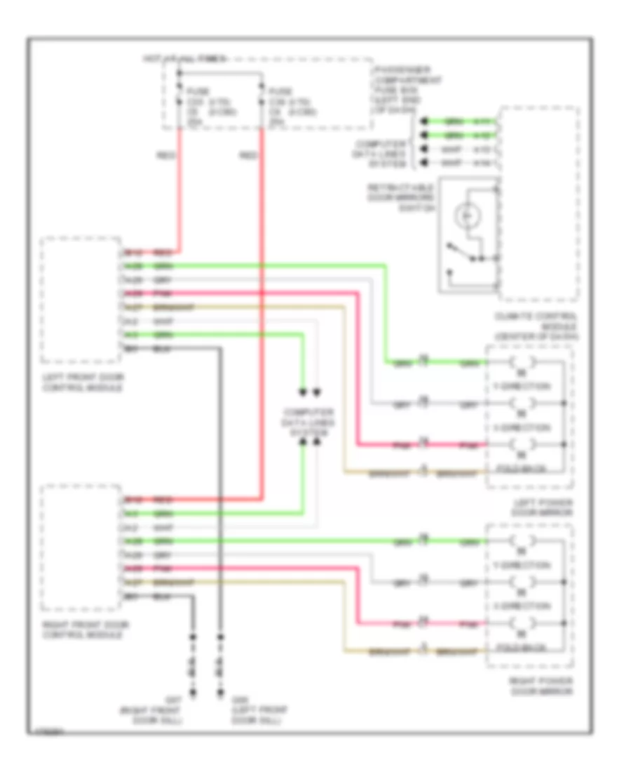
ПРИВОД ЗЕРКАЛ
Электросхема привода зеркал для Volvo V70 2003
Электросхема привода зеркал для Volvo V70 2003 - Список элементов:
- (v70) (xc90)
- A11
- A12
- A13
- A14
- A26
- A27
- A28
- A29
- B12
- Climate control module (center of dash)
- Computer data lines system
- Fold-back
- Fuse c35 c5 25a
- Fuse c36 c6 25a
- G66 (left front door sill)
- G67 (right front door sill)
- Hot at all times
- Left front door control module
- Left power door mirror
- Passenger compartment fuse box (left end of dash)
- Pnk
- Red
- Retractable door mirrors switch
- Right front door control module
- Right power door mirror
- X-direction
- Y-direction
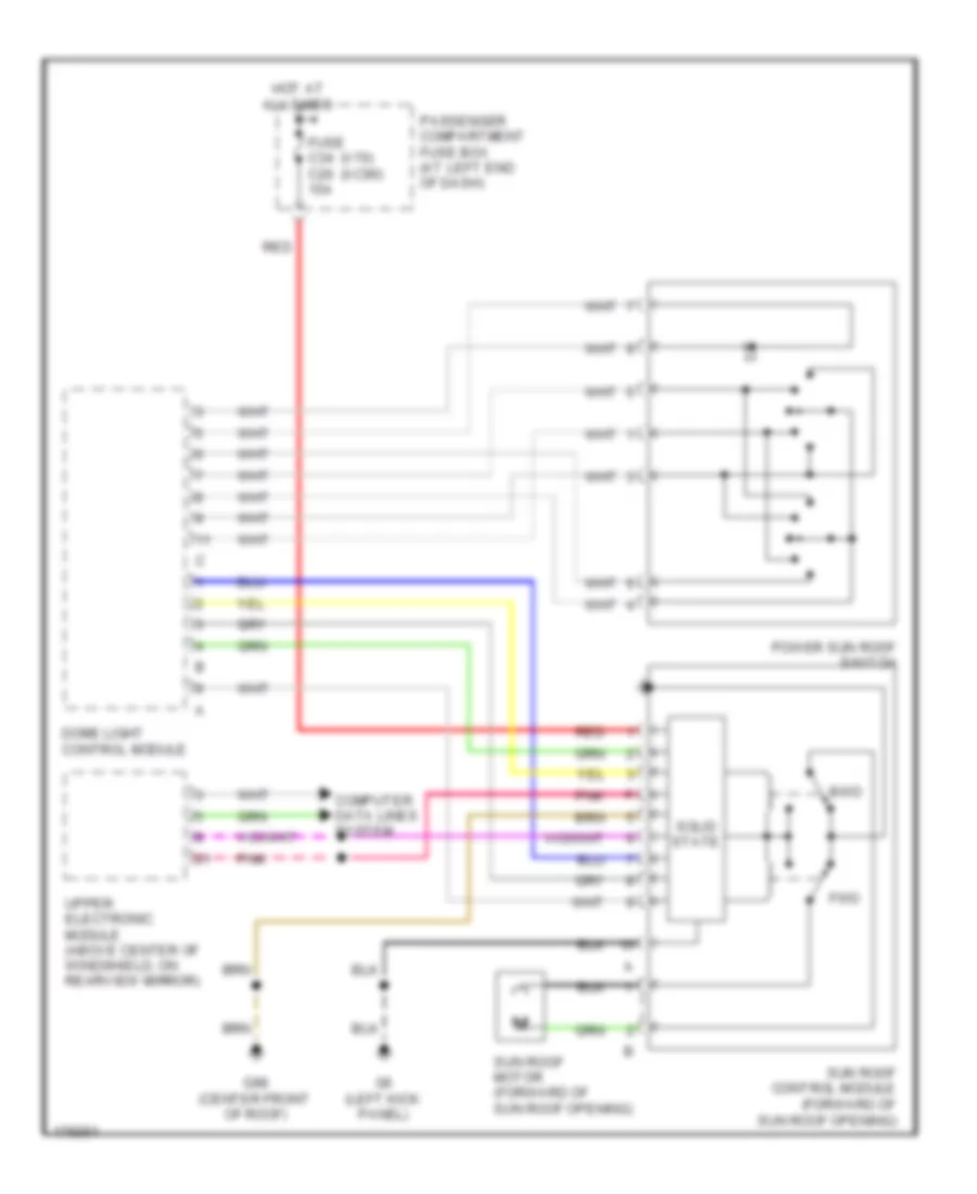
ПРИВОД ЛЮКА И КРЫШИ
Электросхема привода люка для Volvo V70 2003
Электросхема привода люка для Volvo V70 2003 - Список элементов:
- (v70) (xc90)
- Bwd
- Computer data lines system
- Dome light control module
- Fuse c34 c26 15a
- Fwd
- G6 (left kick panel)
- G98 (center front of roof)
- Hot at all times
- Passenger compartment fuse box (at left end of dash)
- Pnk
- Power sun roof switch
- Red
- Solid state
- Sun roof control module (forward of sun roof opening)
- Sun roof motor (forward of sun roof opening)
- Upper electronic module (above center of windshield, on rearview mirror)
ПРИВОД СТЕКЛОПОДЪЕМНИКОВ
Электросхема стеклоподъемников для Volvo V70 2003
Электросхема стеклоподъемников для Volvo V70 2003 - Список элементов:
- (left front door sill) g66
- (right front door sill) g67
- (v70) (xc90)
- A16
- A19
- A23
- A24
- B12
- B17
- B18
- Central electronic module (on passenger compartment relay box)
- Computer data lines system
- Fuse c35 c5 25a
- Fuse c36 c6 25a
- Fuse c37 c7 30a
- G66 (left front door sill)
- G67 (right front door sill)
- Hot at all times
- Left front door control module
- Left front power window motor
- Left rear door power window switch
- Left rear power window down relay
- Left rear power window motor
- Left rear power window up relay
- Passenger compartment fuse box (at left end of dash)
- Rear doors power window child lock relay
- Red
- Right front door control module
- Right front power window motor
- Right rear door power window switch
- Right rear power window down relay
- Right rear power window motor
- Right rear power window up relay
- Solid state
Противоугонная система Сигнализация
Электросхема противоугонной сигнализации для Volvo V70 2003
Электросхема противоугонной сигнализации для Volvo V70 2003 - Список элементов:
- A/c system
- A11
- A12
- A13
- A14
- A15
- A16
- Alarm siren (at right front corner of vehicle)
- B12
- B17
- B18
- C18
- Central electronic module (behind left side of dash, on passenger compartment relay box)
- Climate control module (behind center of dash)
- Computer data lines system
- D20
- Fuse c38 5a
- G47 (rear of left rear door sill)
- G66 (left front door sill)
- G67 (right front door sill)
- G72 (rear of left rear door sill)
- G93 (rear of left front fender)
- G94 (rear of right front fender)
- G98 (center front of roof)
- G99
- Hood alarm contact (left front corner of engine compt)
- Hot at all times
- Instrument cluster
- Key
- Left front door control module (inside left front door)
- Left front door lock unit
- Left glass breakage wire (optional)
- Left rear door lock unit
- Microwave sensor alarm (at rear of sun roof opening)
- Nca
- Passenger compartment fuse box (at left end of dash)
- Pnk
- Rear electronic module (left side of trunk, on cargo compt relay/fuse box)
- Red
- Right front door control module (inside right front door)
- Right front door lock unit
- Right glass breakage wire (optional)
- Right rear door lock unit
- Sun sensor/ electronic immobilizer alarm indicator (top center of dash)
- Switch reduced alarm
- Tail gate lock unit (inside trunk door)
- Tailgate glass breakage sensor (optional)
- Ulk
- Upper electronic module (above center of windshield on rear- view mirror)
- Vehicle inclination sensor (at left rear side of trunk)
- W/ bass speaker
Электросхема иммобилайзера для Volvo V70 2003
Электросхема иммобилайзера для Volvo V70 2003 - Список элементов:
- Antenna ring/ ignition lighting
- B13
- B17
- B18
- Central electronic module (behind left side of dash, on passenger compt relay box)
- Computer data lines system
- D13
- D14
- Driver information module
- Engine control module (at right side of engine compt, forward of strut tower)
- Fuse c25 10a
- G83 (left kick panel)
- Hot at all times
- Ignition switch
- Interior lights system
- Key in ignition switch
- Nca
- Passenger compartment fuse box (at left end of dash)
СИСТЕМА АНТИБЛОКИРОВОЧНОЙ ТОРМОЗНОЙ СИСТЕМЫ ABS
Электросхема антиблокировочной тормозной системы АБС (ABS), С Динамическое Управление Стабильностью для Volvo V70 2003
Электросхема антиблокировочной тормозной системы АБС (ABS), С Динамическое Управление Стабильностью для Volvo V70 2003 - Список элементов:
- (v70) (xc90)
- A11
- A12
- A13
- A14
- A37
- A55
- Abs control module (on left rear of engine compt)
- Abs pump motor
- B13
- B17
- B18
- B26
- Brake light contact
- Brake pedal sensor
- Brake pressure sensor 1 (on brake master cylinder)
- Brake pressure sensor 2 (on brake master cylinder)
- Central electronic module (behind left side of dash)
- Climate control module
- Computer data lines system
- Contact reel
- D12
- Driver information module
- Dstc activation unit (at steering column)
- Dstc sensor module
- Engine compartment relay/fuse box (left side of engine compt)
- Engine control module (right side of engine compt)
- Fuse b12 5a
- Fuse b14 30a
- Fuse b19 30a
- Fuse c9 c17 5a
- G84 (right kick panel)
- G93 (rear of left fender)
- G95 (rear of left front fender)
- Hot at all times
- Hot in on or start
- Hot with engine running
- Left front abs sensor (on wheel hub)
- Left rear abs sensor (on wheel hub)
- Passenger compartment fuse box (at left end of dash)
- Pnk
- Red
- Right front abs sensor (on wheel hub)
- Right rear abs sensor (on wheel hub)
- Spin control switch
- Steering angle sensor module
- Steering wheel module (swm)
- Vacuum pump (left rear of engine)
- Vacuum pump switch (front of engine compt)
Электросхема антиблокировочной тормозной системы АБС (ABS), без Динамическое Управление Стабильностью для Volvo V70 2003
Электросхема антиблокировочной тормозной системы АБС (ABS), без Динамическое Управление Стабильностью для Volvo V70 2003 - Список элементов:
- A11
- A12
- A13
- A14
- Abs control module (on left rear of engine compt)
- Abs pump motor
- B13
- B17
- B18
- B26
- Brake light contact
- Brake pedal sensor
- Central electronic module (behind left side of dash)
- Climate control module
- Computer data lines system
- Engine compartment relay/fuse box (left side of engine compt)
- Engine control module (right side of engine compt)
- Fuse b12 5a
- Fuse b14 30a
- Fuse b19 30a
- Fuse c9 5a
- G93 (rear of left fender)
- G95 (rear of left front fender)
- Hot at all times
- Hot in on or start
- Hot with engine running
- Instrument cluster
- Left front abs sensor (on wheel hub)
- Left rear abs sensor (on wheel hub)
- Passenger compartment fuse box (at left end of dash)
- Red
- Right front abs sensor (on wheel hub)
- Right rear abs sensor (on wheel hub)
- Spin control switch
- Vacuum pump (left rear of engine)
- Vacuum pump switch (front of engine compt)
СИСТЕМА КОНДИЦИОНЕРА
Электросхема кондиционера (1 из 2) для Volvo V70 2003
Электросхема кондиционера (1 из 2) для Volvo V70 2003 - Список элементов:
- (not used)
- (right kick panel) g84
- 15/20
- 15/23
- 15/30
- 2.4l
- A/c relay
- A/c solenoid switch
- A10
- A11
- A12
- A13
- A14
- A15
- A16
- Air quality sensor (at right side of plenum)
- B10
- B11
- B12
- B13
- B14
- B15
- B16
- B17
- B18
- B19
- B20
- B21
- B22
- Central electronic module (cem) (behind left side of dash)
- Computer data lines system
- Defroster damper motor (near center of hvac housing)
- Electronic climate control (ecc) module
- Engine compartment fuse/relay box (at left side of cargo compt)
- Extended x-feed relay
- Fuse a8 60a
- Fuse b11 20a
- Fuse b8 10a
- Fuse c23 5a
- Fuse c24 10a
- Fuse c26 30a
- Hot at all times
- Hot in on or start
- Nca
- Passenger compartment fuse box (at left end of dash)
- Recirculation damper motor (on lower right side of hvac housing)
- Red
- Solid state
- Ventilation/floor damper motor (near center of hvac housing)
Электросхема кондиционера (2 из 2) для Volvo V70 2003
Электросхема кондиционера (2 из 2) для Volvo V70 2003 - Список элементов:
- (rear of left front fender) g2
- (right kick panel) g10
- 2.3l & 2.4l turbo
- 2.4l
- A14
- A18
- A21
- A37
- A39
- A40
- A55
- A58
- A60
- A61
- A68
- B13
- B44
- Climate control system pressure sensor (at right front of engine compartment)
- Computer data lines system
- Coolant temperature sensor (on front of engine)
- Cooling fan control module (at front center of engine compt)
- Electric cooling fan motor
- Engine control module (ecm) (right side of engine compt)
- Evaporator temperature sensor (near center of hvac housing)
- Fan control module (behind right side of dash)
- Left side temperature damper motor (on left end of hvac housing)
- Nca
- Outside temperature sensor
- Passenger compartment fan motor (on lower right side of hvac housing)
- Red
- Right front door control module (pdm/ddm)
- Right power door mirror
- Right side temperature damper motor (near center of hvac housing)
- Solar sensor, indicator alarm & electronic immobilizer (on top center of dash)
- Solid state
Электросхема кондиционера с ручный управлением для Volvo V70 2003
Электросхема кондиционера с ручный управлением для Volvo V70 2003 - Список элементов:
- (not
- (right kick panel) g10
- (right kick panel) g84
- 15/20
- 15/23
- 15/30
- 2.3l & 2.4l turbo
- 2.4l
- A/c relay
- A/c solenoid switch
- A10
- A11
- A12
- A13
- A14
- A15
- A16
- A21
- A39
- A40
- A58
- A60
- A61
- A68
- B10
- B11
- B12
- B13
- B14
- B15
- B16
- B17
- B18
- B19
- B20
- B21
- B22
- B44
- Central electronic module (cem) (behind left side of dash)
- Climate control system pressure sensor (at right front of engine compt)
- Computer data lines system
- Coolant temperature sensor (on front of engine)
- Cooling fan control module (at front center of engine compt)
- Electric cooling fan motor
- Engine compartment fuse/relay box (at left side of cargo compartment)
- Engine control module (ecm) (right side of engine compt)
- Evaporator temperature sensor (near center of hvac housing)
- Extended x feed relay
- Fan control module (behind right side of dash)
- Fuse b11 20a
- Fuse b8 10a
- Fuse b8 60a
- Fuse c23 5a
- Fuse c24 10a
- Fuse c26 30a
- G2 (rear of left front fender)
- Hot at all times
- Hot in on or start
- Left side temperature damper motor
- Manual climate control module (ccm)
- Nca
- Passenger compartment fan motor (on lower right side of hvac housing)
- Passenger compartment fuse box (at left end of dash)
- Recirculation damper motor (on lower right side of hvac housing)
- Red
- Right side temperature damper motor
- Solid state
- Used)
- Ventilation/floor/defroster damper motor (near center of hvac housing)
СИСТЕМА КРУИЗКОНТРОЛЯ
Электросхема системы круизконтроля для Volvo V70 2003
Электросхема системы круизконтроля для Volvo V70 2003 - Список элементов:
- A19
- A20
- A25
- A35
- A36
- A43
- A59
- Accelerator pedal position sensor (near accelerator pedal)
- B11
- B13
- B15
- B17
- B18
- B25
- B38
- Body control module (at left rear corner of engine compt)
- Brake pedal sensor (at left rear corner of engine compt)
- Central electronic module (behind left side of dash, on passenger compt relay box)
- Clutch pedal sensor (m/t) (behind left side of dash)
- Computer data lines system
- Contact reel
- Cruise control switch
- Engine compartment relay/fuse box (at left side of engine compartment, forward of strut tower)
- Engine control module (on right side of engine compartment, forward of strut tower)
- Engine management system main relay
- Engine throttle body (non-turbo) (front of engine)
- Engine throttle body (turbo) (front of engine)
- Fuse b23 5a
- Fuse b8 20a
- G93 (rear of left front fender)
- Hot at all times
- Instrument cluster
- Left front abs speed sensor (behind wheel, on spindle/ hub assembly)
- Non- turbo
- Red
- Right front abs speed sensor (behind wheel, on spindle/ hub assembly)
- Steering wheel module
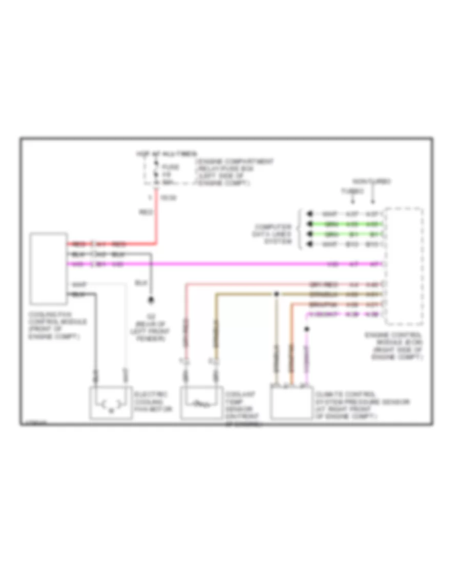
- Turbo
СИСТЕМА ОХЛАЖДЕНИЯ
Электросхема системы охлаждения для Volvo V70 2003
Электросхема системы охлаждения для Volvo V70 2003 - Список элементов:
- 15/30
- A21
- A37
- A39
- A40
- A55
- A58
- A60
- A61
- A68
- B13
- Climate control system pressure sensor (at right front of engine compt)
- Computer data lines system
- Coolant temp. sensor (on front of engine)
- Cooling fan control module (front of engine compt)
- Electric cooling fan motor
- Engine compartment relay/fuse box (left side of engine compt)
- Engine control module (ecm) (right side of engine compt)
- Fuse a8 60a
- G2 (rear of left front fender)
- Hot at all times
- Non-turbo
- Red
- Turbo
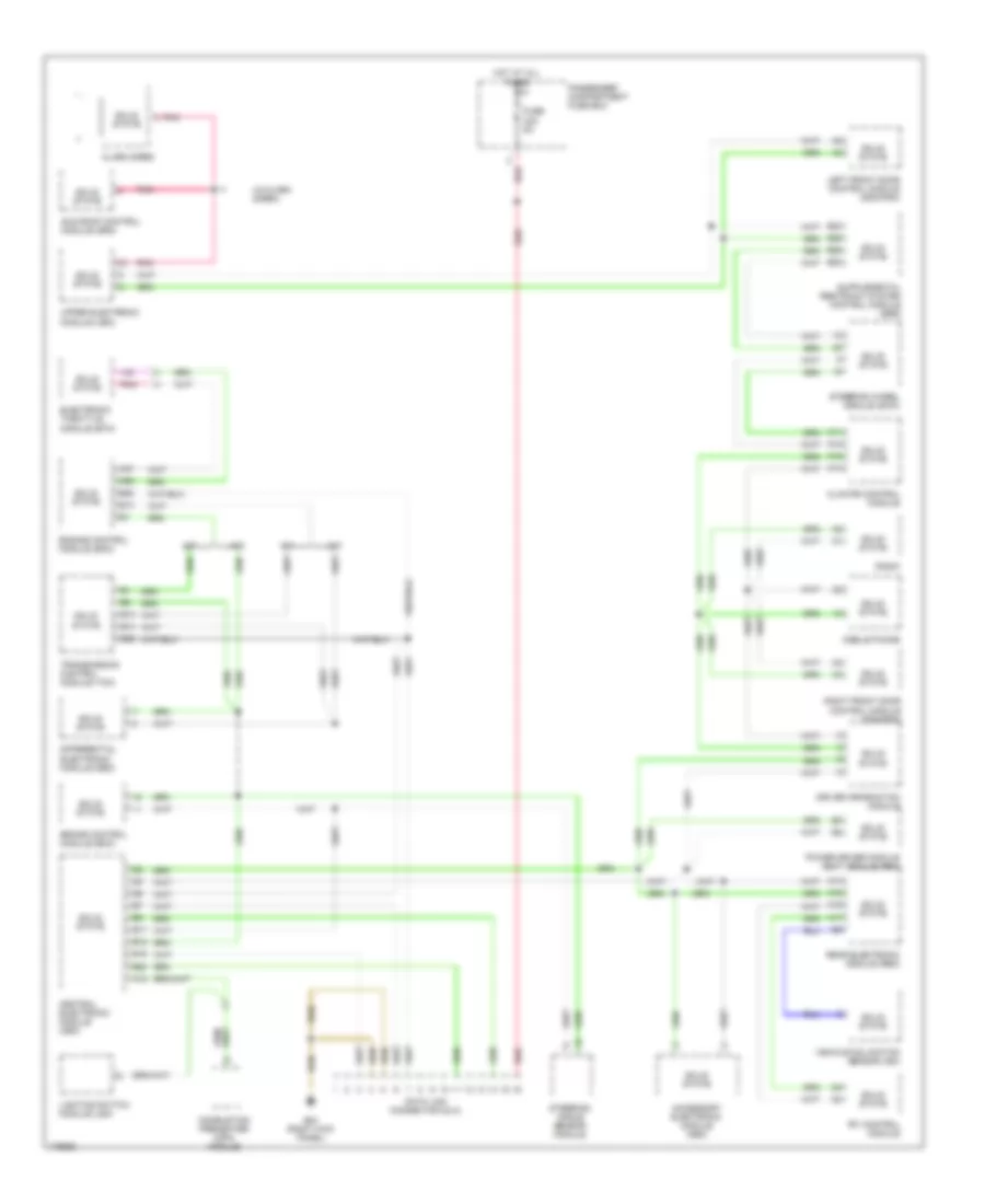
СИСТЕМА ПЕРЕДАЧИ ДАННЫХ
Электросхема линии передачи данных CAN для Volvo V70 2003
Электросхема линии передачи данных CAN для Volvo V70 2003 - Список элементов:
- (w/alarm siren)
- A/t
- A11
- A12
- A13
- A14
- A15
- A16
- A17
- A18
- A37
- A55
- Accessory electronic module (aem)
- Alarm siren
- B13
- B14
- B17
- B18
- B19
- B20
- B22
- B23
- B24
- B25
- B26
- Brake control module (bcm)
- Central electronic module (cem)
- Climate control module
- Combustion preheater (cpm) module
- Data link connector (dlc)
- Differential electronic module (dem)
- Driver information module
- Electronic throttle module (etm)
- Engine control module (ecm)
- Fuse c23 5a
- G84 (right kick panel)
- Hot at all times
- Left front door control module (ddm/pdm)
- Lighting switch module (lsm)
- M/t
- Mobile phone
- Passenger compartment fuse box
- Pnk
- Power driver module seat module (psm)
- Radio
- Rear electronic module (rem)
- Red
- Right front door control module (ddm/pdm)
- Rti control module
- Solid state
- Steering angle sensor module
- Steering wheel module (swm)
- Sun roof control module (srm)
- Transmission control module (tcm)
- Upper electronic module (uem)
- Vehicle inclination sensor (ism)
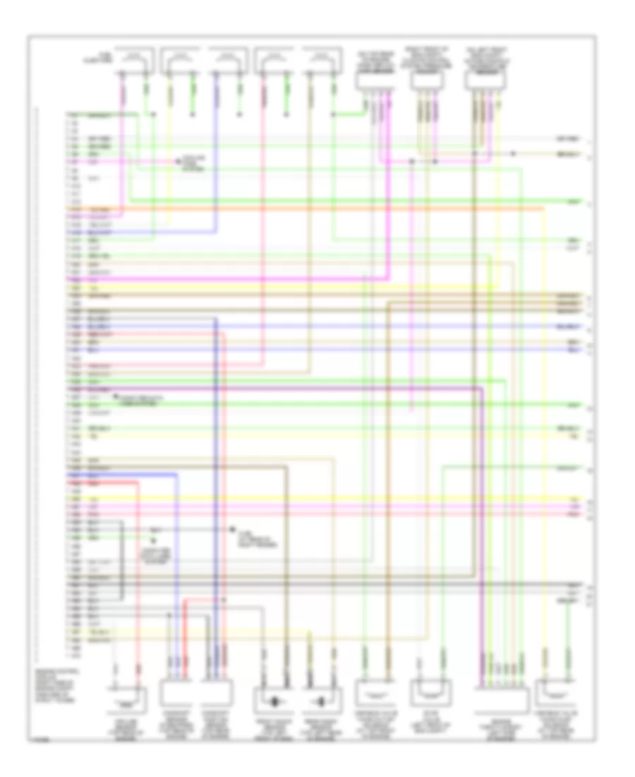
СИСТЕМА УПРАВЛЕНИЯ ДВИГАТЕЛЯ
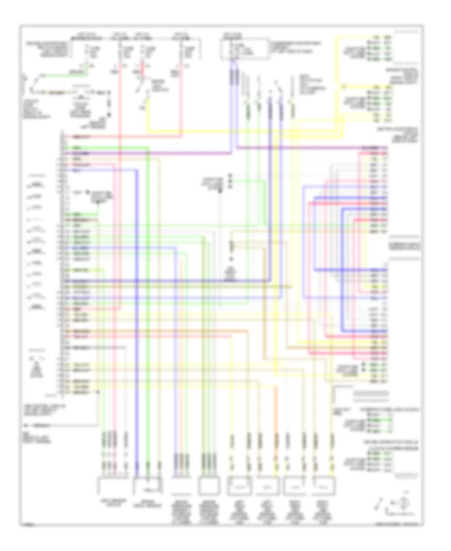
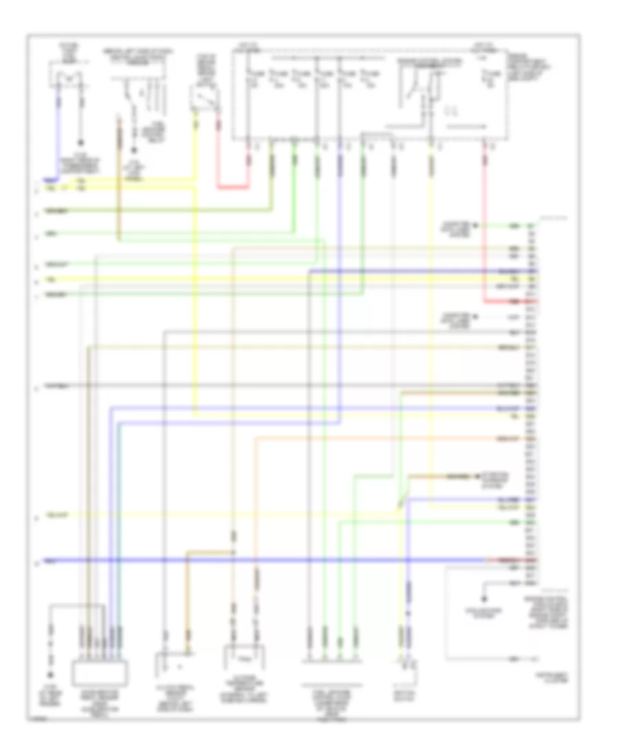
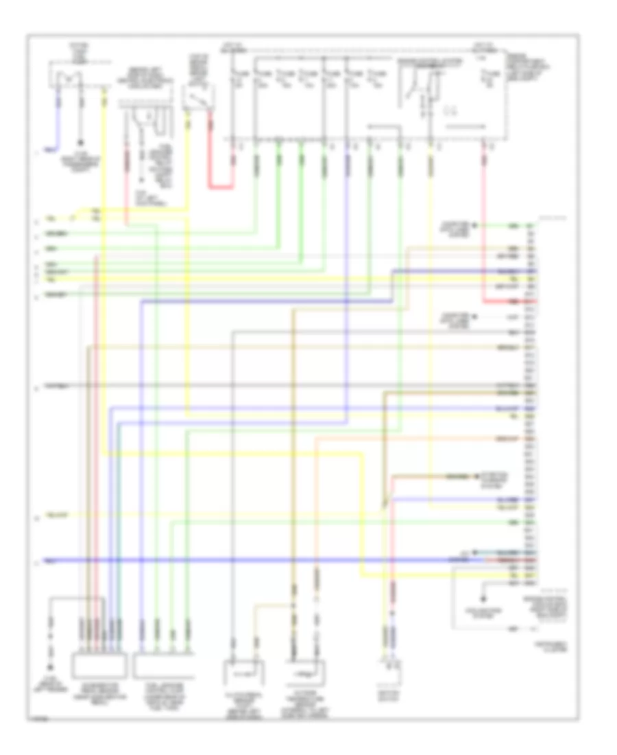
2.3L ТУРБО
2.3L турбо, Электросхема системы управления двигателем (1 из 3) для Volvo V70 2003
2.3L турбо, Электросхема системы управления двигателем (1 из 3) для Volvo V70 2003 - Список элементов:
- (on left front eng compt) intake manifold temperature sensor
- (on top rear of engine) mass airflow (maf) sensor
- (right front of eng compt) climate control system pressure sensor
- 31/96 (at rear of right fender)
- A10
- A11
- A12
- A13
- A14
- A15
- A16
- A17
- A18
- A19
- A20
- A21
- A22
- A23
- A24
- A25
- A26
- A27
- A28
- A29
- A30
- A31
- A32
- A33
- A34
- A35
- A36
- A37
- A38
- A39
- A40
- A41
- A42
- A43
- A44
- A45
- A46
- A47
- A48
- A49
- A50
- A51
- A52
- A53
- A54
- A55
- A56
- A57
- A58
- A59
- A60
- A61
- A62
- A63
- A64
- A65
- A66
- A67
- A68
- A69
- A70
- Camshaft position sensor (top rear of engine)
- Camshaft sensor (if equipped) (top rear of engine)
- Computer data lines system
- Cooling fans system
- Engine control module (right side of engine compt, forward of strut tower)
- Engine throttle body (left side of engine)
- Evap valve (left front of eng compt)
- Front knock sensor (top left front of eng)
- Fuel injectors
- Impulse sensor (top rear of engine)
- Nac
- Nca
- Pnk
- Rear knock sensor (top left rear of engine)
- Red
- Variable valve timing inlet solenoid (at top rear of engine)
- Variable valve timing outlet solenoid (at top front of engine)
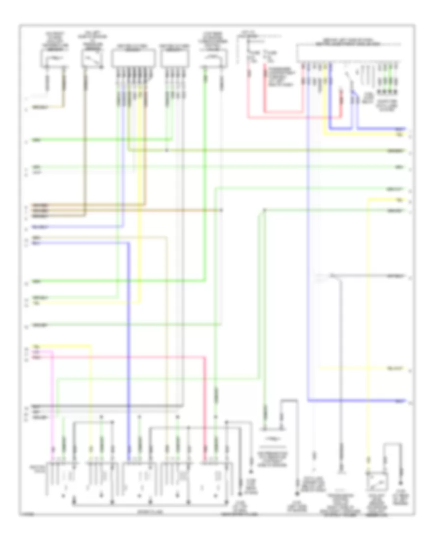
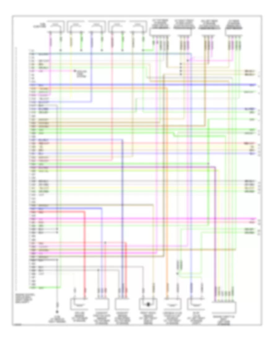
2.3L турбо, Электросхема системы управления двигателем (2 из 3) для Volvo V70 2003
2.3L турбо, Электросхема системы управления двигателем (2 из 3) для Volvo V70 2003 - Список элементов:
- (behind left side of dash) central electronic module (cem)
- (on front of eng) coolant temperature sensor
- (on left side of engine) oil pressure sensor
- (top rear of engine) turbocharger control valve
- 31/88 (at top of eng, near spark plugs)
- 31/89 (top rear of eng)
- 31/91 (left side of engine)
- 31/93 (at rear of left fender)
- A20
- Air preheating ptc resistor (top right side of engine)
- B14
- B17
- B18
- B22
- C14
- Computer data lines system
- Coolant level sensor (on engine coolant reservoir)
- Data link connector (below left side of dash)
- Fuel pump relay
- Fuse 10a
- Fuse 15a
- Heated oxygen sensor
- Heated oxygen sensor 1
- Hot at all times
- Ignition coils
- Nca
- Passenger compartment fuse box (at left end of dash)
- Pnk
- Red
- Spark plugs
- Transmission control module (right side of eng compt, forward of strut tower)
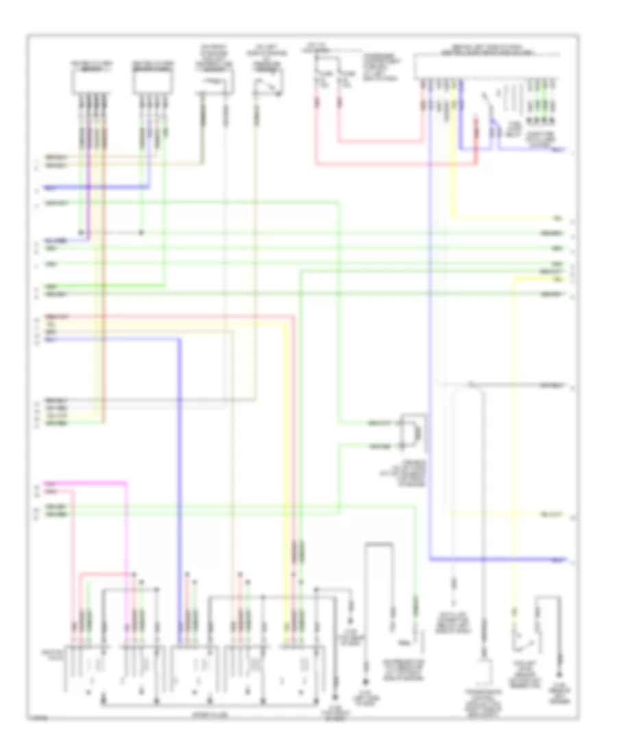
2.3L турбо, Электросхема системы управления двигателем (3 из 3) для Volvo V70 2003
2.3L турбо, Электросхема системы управления двигателем (3 из 3) для Volvo V70 2003 - Список элементов:
- (behind left side of dash) central electronic module
- (in fuel tank) fuel pump
- (top of brake pedal) brake light switch
- 31/48 (right rear of passenger's compartment)
- 31/6 (at left kick panel)
- 31/93 (at rear of left fender)
- Accelerator pedal sensor (near accelerator pedal)
- B10
- B11
- B12
- B13
- B14
- B15
- B16
- B17
- B18
- B19
- B20
- B21
- B22
- B23
- B24
- B25
- B26
- B27
- B28
- B29
- B30
- B31
- B32
- B33
- B34
- B35
- B36
- B37
- B38
- B39
- B40
- B41
- B42
- B43
- B44
- B45
- B46
- B47
- B48
- Clutch pedal sensor (w/m/t) (behind left side of dash)
- Computer data lines system
- Cooling fans system
- Engine compartment relay/fuse box (left side of eng compt)
- Engine control module (ecm) (right side of engine compt, forward of strut tower)
- Engine control system main relay
- Fuel leakage control pump (under rear of vehicle, near fuel tank)
- Fuel leakage control relay
- Fuse 10a
- Fuse 15a
- Fuse 20a
- Fuse 5a
- Hot at all times
- Ignition switch
- Instrument cluster
- Nca
- Outside temperature sensor (integral to left sideview mirror)
- Red
- Starting/ charging system
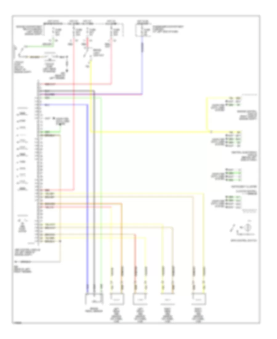
2.4L
2.4L, Электросхема системы управления двигателем (1 из 3) для Volvo V70 2003
2.4L, Электросхема системы управления двигателем (1 из 3) для Volvo V70 2003 - Список элементов:
- (at rear of engine) pressure & temp sensor
- (at right front of eng compt) climate control pressure sensor
- (at top rear of engine) mass airflow (maf) sensor
- (on left rear of engine) intake manifold pressure sensor
- 31/96 (at rear of right fender)
- A10
- A11
- A12
- A13
- A14
- A15
- A16
- A17
- A18
- A19
- A20
- A21
- A22
- A23
- A24
- A25
- A26
- A27
- A28
- A29
- A30
- A31
- A32
- A33
- A34
- A35
- A36
- A37
- A38
- A39
- A40
- A41
- A42
- A43
- A44
- A45
- A46
- A47
- A48
- A49
- A50
- A51
- A52
- A53
- A54
- A55
- A56
- A57
- A58
- A59
- A60
- A61
- A62
- A63
- A64
- A65
- A66
- A67
- A68
- A69
- A70
- Camshaft position (cmp) sensor (on top rear of engine)
- Camshaft sensor (if equipped) (on top rear of engine)
- Cooling fans system
- Engine control module (ecm) (right side of eng compt)
- Engine throttle body (left side of engine)
- Evap valve (at left front of engine compt)
- Front knock sensor (at left front side of engine)
- Fuel injectors
- Impulse sensor (at top rear of engine)
- Pnk
- Red
- Variable valve timing outlet solenoid (at top front of engine)
2.4L, Электросхема системы управления двигателем (2 из 3) для Volvo V70 2003
2.4L, Электросхема системы управления двигателем (2 из 3) для Volvo V70 2003 - Список элементов:
- (behind left side of dash) central electronic module (cem)
- (on front of engine) coolant temperature sensor
- (on left side of engine) oil pressure sensor
- 31/88 (top front of eng)
- 31/89 (top rear of eng)
- 31/91 (left side of eng)
- 31/93 (rear of left fender)
- A20
- Air preheating ptc resistor (at top right side of engine)
- B14
- B17
- B18
- B22
- C14
- Computer data lines system
- Coolant level sensor (on coolant reservoir)
- Data link connector (below left side of dash)
- Fuel pump relay
- Fuse 10a
- Fuse 15a
- Heated oxygen sensor
- Heated oxygen sensor (ho2s) 1
- Hot at all times
- Ignition coils
- Nca
- Passenger compartment fuse box (at left end of dash)
- Pnk
- Red
- Spark plugs
- Transmission control module (tcm) (right side of eng compt)
- Variable valve timing outlet solenoid (top front of engine)
2.4L, Электросхема системы управления двигателем (3 из 3) для Volvo V70 2003
2.4L, Электросхема системы управления двигателем (3 из 3) для Volvo V70 2003 - Список элементов:
- (behind left side of dash) central electronic module (cem)
- (in fuel tank) fuel pump
- (top of brake pedal) brake light switch
- 31/48 (right rear of passenger's compt)
- 31/6 (at left kick panel)
- 31/93 (rear of left fender)
- A/c system
- Accelerator pedal sensor (near accelerator pedal)
- B10
- B11
- B12
- B13
- B14
- B15
- B16
- B17
- B18
- B19
- B20
- B21
- B22
- B23
- B24
- B25
- B26
- B27
- B28
- B29
- B30
- B31
- B32
- B33
- B34
- B35
- B36
- B37
- B38
- B39
- B40
- B41
- B42
- B43
- B44
- B45
- B46
- B47
- B48
- Clutch pedal sensor (w/m/t) (behind left side of dash)
- Computer data lines system
- Cooling fans system
- Engine compartment relay/fuse box (left side of eng compt)
- Engine control module (ecm) (right side of eng compt)
- Engine control system main relay
- Fuel leakage control pump (under rear of vehicle, near fuel tank)
- Fuel leakage control relay (on pass compt relay box)
- Fuse 10a
- Fuse 15a
- Fuse 20a
- Fuse 5a
- Hot at all times
- Ignition switch
- Instrument cluster
- Nca
- Outside temperature sensor (integral to left sideview mirror)
- Red
- Starting/ charging system
2.4L ТУРБО
2.4L турбо, Электросхема системы управления двигателем (1 из 3) для Volvo V70 2003
2.4L турбо, Электросхема системы управления двигателем (1 из 3) для Volvo V70 2003 - Список элементов:
- (on left front eng compt) intake manifold temperature sensor
- (on top rear of engine) mass airflow (maf) sensor
- (right front of eng compt) climate control system pressure sensor
- 31/96 (at rear of right fender)
- A10
- A11
- A12
- A13
- A14
- A15
- A16
- A17
- A18
- A19
- A20
- A21
- A22
- A23
- A24
- A25
- A26
- A27
- A28
- A29
- A30
- A31
- A32
- A33
- A34
- A35
- A36
- A37
- A38
- A39
- A40
- A41
- A42
- A43
- A44
- A45
- A46
- A47
- A48
- A49
- A50
- A51
- A52
- A53
- A54
- A55
- A56
- A57
- A58
- A59
- A60
- A61
- A62
- A63
- A64
- A65
- A66
- A67
- A68
- A69
- A70
- Camshaft position sensor (top rear of engine)
- Camshaft sensor (if equipped) (top rear of engine)
- Computer data lines system
- Cooling fans system
- Engine control module (right side of engine compt, forward of strut tower)
- Engine throttle body (left side of engine)
- Evap valve (left front of eng compt)
- Front knock sensor (top left front of eng)
- Fuel injectors
- Impulse sensor (top rear of engine)
- Nac
- Nca
- Pnk
- Rear knock sensor (top left rear of engine)
- Red
- Variable valve timing inlet solenoid (at top rear of engine)
- Variable valve timing outlet solenoid (at top front of engine)
2.4L турбо, Электросхема системы управления двигателем (2 из 3) для Volvo V70 2003
2.4L турбо, Электросхема системы управления двигателем (2 из 3) для Volvo V70 2003 - Список элементов:
- (behind left side of dash) central electronic module (cem)
- (on front of eng) coolant temperature sensor
- (on left side of engine) oil pressure sensor
- (top rear of engine) turbocharger control valve
- 31/88 (at top of eng, near spark plugs)
- 31/89 (top rear of eng)
- 31/91 (left side of engine)
- 31/93 (at rear of left fender)
- A20
- Air preheating ptc resistor (top right side of engine)
- B14
- B17
- B18
- B22
- C14
- Computer data lines system
- Coolant level sensor (on engine coolant reservoir)
- Data link connector (below left side of dash)
- Fuel pump relay
- Fuse 10a
- Fuse 15a
- Heated oxygen sensor
- Heated oxygen sensor 1
- Hot at all times
- Ignition coils
- Nca
- Passenger compartment fuse box (at left end of dash)
- Pnk
- Red
- Spark plugs
- Transmission control module (right side of eng compt, forward of strut tower)
2.4L турбо, Электросхема системы управления двигателем (3 из 3) для Volvo V70 2003
2.4L турбо, Электросхема системы управления двигателем (3 из 3) для Volvo V70 2003 - Список элементов:
- (behind left side of dash) central electronic module
- (in fuel tank) fuel pump
- (top of brake pedal) brake light switch
- 31/48 (right rear of passenger's compartment)
- 31/6 (at left kick panel)
- 31/93 (at rear of left fender)
- Accelerator pedal sensor (near accelerator pedal)
- B10
- B11
- B12
- B13
- B14
- B15
- B16
- B17
- B18
- B19
- B20
- B21
- B22
- B23
- B24
- B25
- B26
- B27
- B28
- B29
- B30
- B31
- B32
- B33
- B34
- B35
- B36
- B37
- B38
- B39
- B40
- B41
- B42
- B43
- B44
- B45
- B46
- B47
- B48
- Clutch pedal sensor (w/m/t) (behind left side of dash)
- Computer data lines system
- Cooling fans system
- Engine compartment relay/fuse box (left side of eng compt)
- Engine control module (ecm) (right side of engine compt, forward of strut tower)
- Engine control system main relay
- Fuel leakage control pump (under rear of vehicle, near fuel tank)
- Fuel leakage control relay
- Fuse 10a
- Fuse 15a
- Fuse 20a
- Fuse 5a
- Hot at all times
- Ignition switch
- Instrument cluster
- Nca
- Outside temperature sensor (integral to left sideview mirror)
- Red
- Starting/ charging system
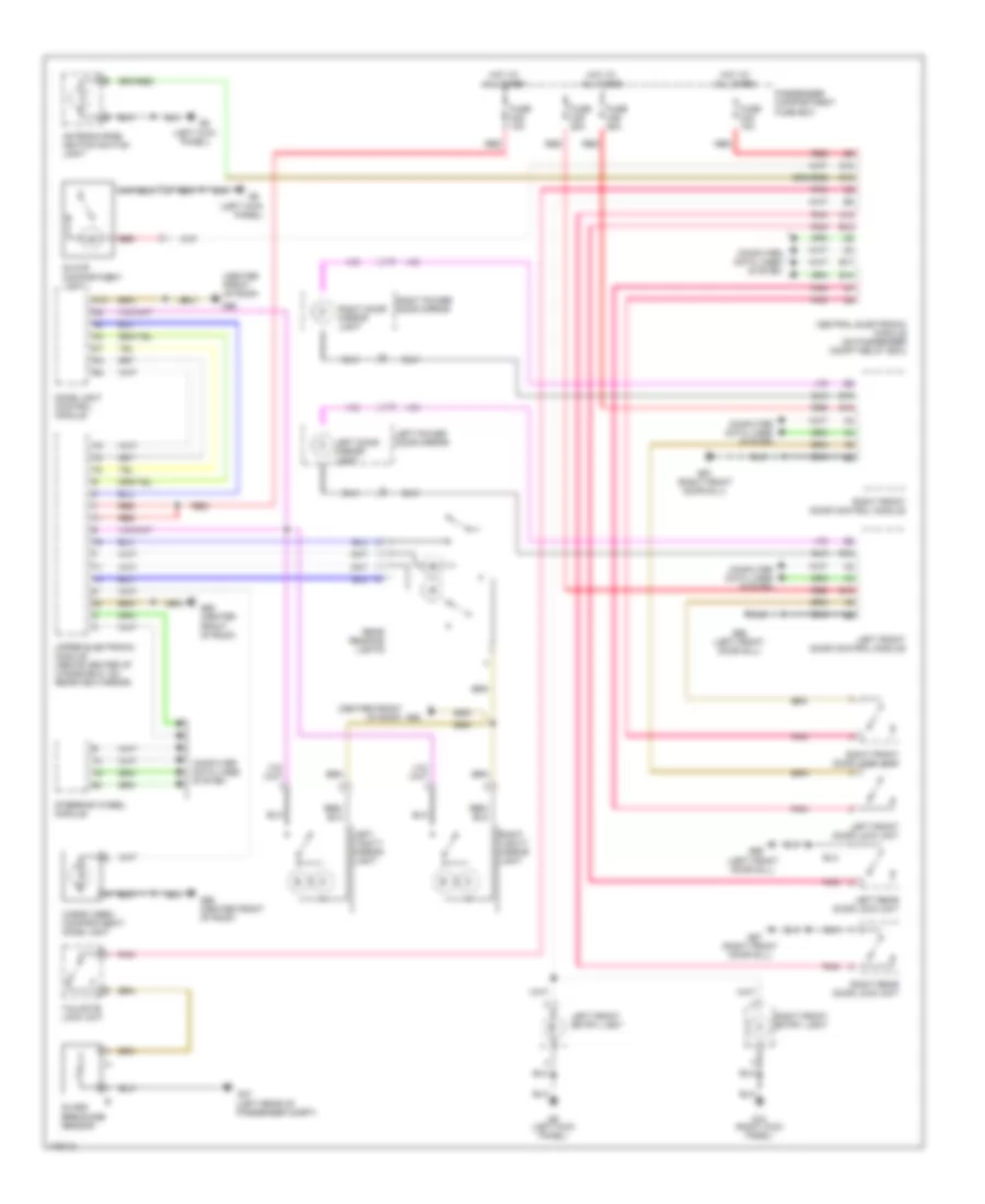
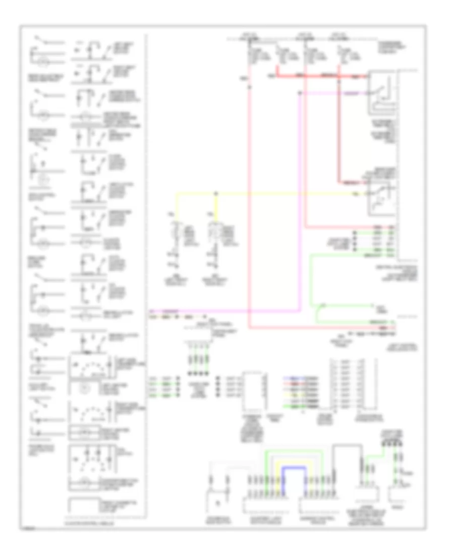
Система Фар
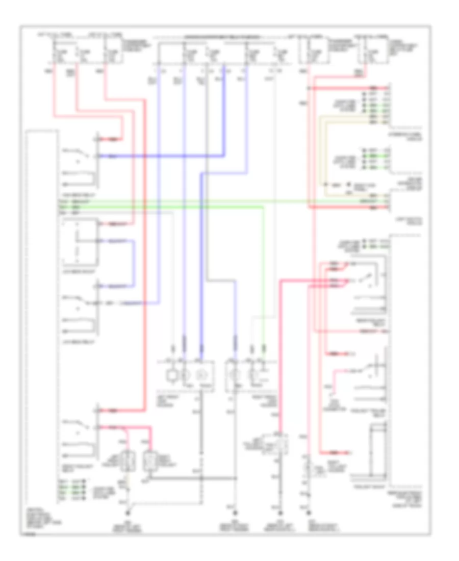
Электросхема фар, С ксеноновые лампы для Volvo V70 2003
Электросхема фар, С ксеноновые лампы для Volvo V70 2003 - Список элементов:
- (right kick panel)
- A14
- A16
- A18
- B17
- B18
- Bix
- Cargo compartment relay/fuse box
- Central electronic module (cem) (behind left side of dash)
- Computer data lines system
- D11
- Driver information module
- Engine compartment relay/fuse box
- Fog- light
- Foglight shunt
- Foglight trailer relay
- Front foglight relay
- Fuse b17 10a
- Fuse b18 10a
- Fuse b20 15a
- Fuse b21 15a
- Fuse c1 15a
- Fuse c18 15a
- Fuse c2 20a
- Fuse c23 5a
- Fuse d2 10a
- G72 (rear of left rear door sill)
- G73 (rear of right rear door sill)
- G84
- G93 (rear of left front fender)
- G94 (rear of right front fender)
- High beam relay
- Hot at all times
- Left front foglight
- Left front lamp housing
- Left taillight housing
- Light switch module
- Low beam relay
- Low beam shunt
- Main
- Passenger compartment fuse box
- Pnk
- Rear electronic module (rem) (at left side of trunk)
- Rear foglight relay
- Red
- Right front foglight
- Right front lamp housing
- Right taillight housing
- Steering wheel module
- Tow hitch connector
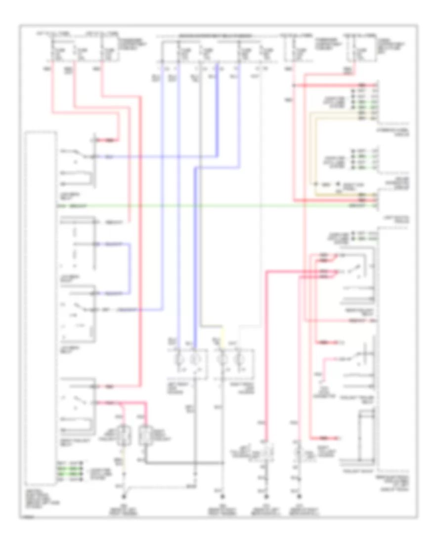
Электросхема фар, без Ксеноновые лампы для Volvo V70 2003
Электросхема фар, без Ксеноновые лампы для Volvo V70 2003 - Список элементов:
- (rear of right rear door sill)
- (right kick panel)
- A14
- A16
- A18
- B17
- B18
- Cargo compartment relay/fuse box
- Central electronic module (cem) (behind left side of dash)
- Computer data lines system
- Driver information module
- Engine compartment relay/fuse box
- Fog- light
- Foglight shunt
- Foglight trailer relay
- Front foglight relay
- Fuse b17 10a
- Fuse b18 10a
- Fuse b20 15a
- Fuse b21 15a
- Fuse c1 15a
- Fuse c18 15a
- Fuse c2 20a
- Fuse c23 5a
- Fuse d2 10a
- G72 (rear of left rear door sill)
- G73
- G84
- G93 (rear of left front fender)
- G94 (rear of right front fender)
- High beam relay
- Hot at all times
- Left front foglight
- Left front lamp housing
- Left taillight housing
- Light switch module
- Low beam relay
- Low beam shunt
- Passenger compartment fuse box
- Pnk
- Rear electronic module (rem) (at left side of trunk)
- Rear foglight relay
- Red
- Right front foglight
- Right front lamp housing
- Right taillight housing
- Steering wheel module
- Tow hitch connector
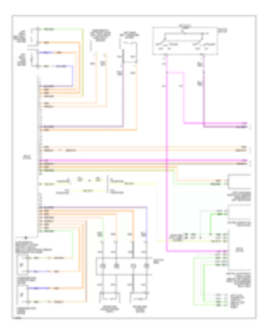
СИСТЕМЫ ПАМЯТИ
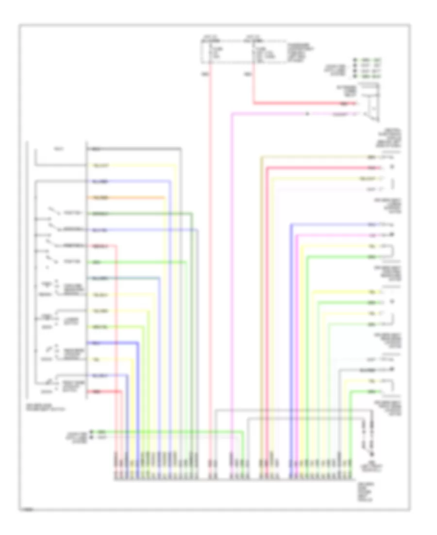
Электросхема памяти водительского сиденья для Volvo V70 2003
Электросхема памяти водительского сиденья для Volvo V70 2003 - Список элементов:
- (v70) (xc90)
- B17
- B18
- Back
- C10
- C11
- C12
- C13
- C14
- C15
- C16
- Central electronic module (behind left side of dash)
- Computer data lines system
- Down
- Driver's seat forward/ rearward motor
- Driver's seat front edge up/down motor
- Driver's seat lumbar support motor
- Driver's seat rear edge up/down motor
- Driver's side power seat module
- Driver's side power seat switch
- E10
- E11
- E12
- Extended x-feed relay
- Forw
- Forward/ rearward switch
- Front edge up/down switch
- Fuse c24 c21 10a
- Fuse c3 30a
- G66 (left front door sill)
- Hot at all times
- Lumbar switch
- Passenger compartment fuse box (left end of dash)
- Pnk
- Position
- Position 1
- Position 2
- Position 3
- Rear edge up/down switch
- Rearw
- Red
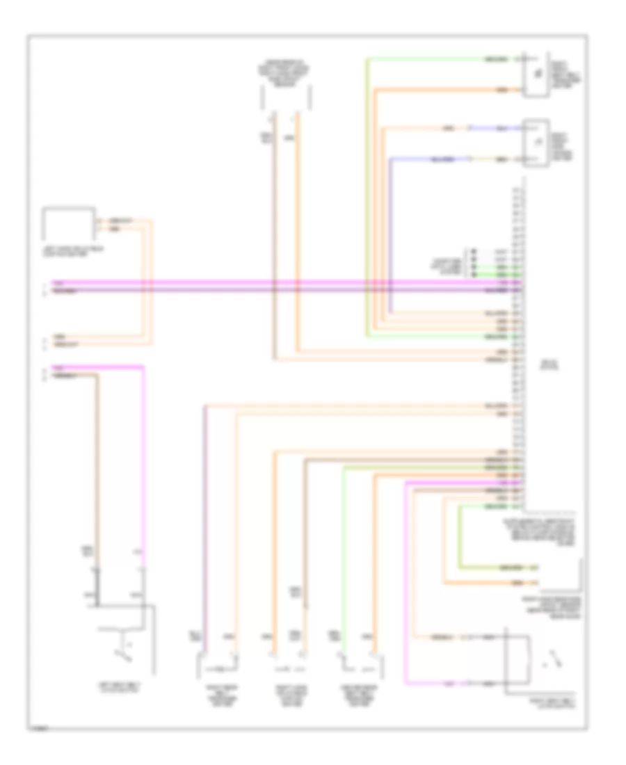
СИСТЕМЫ СИДЕНИЙ
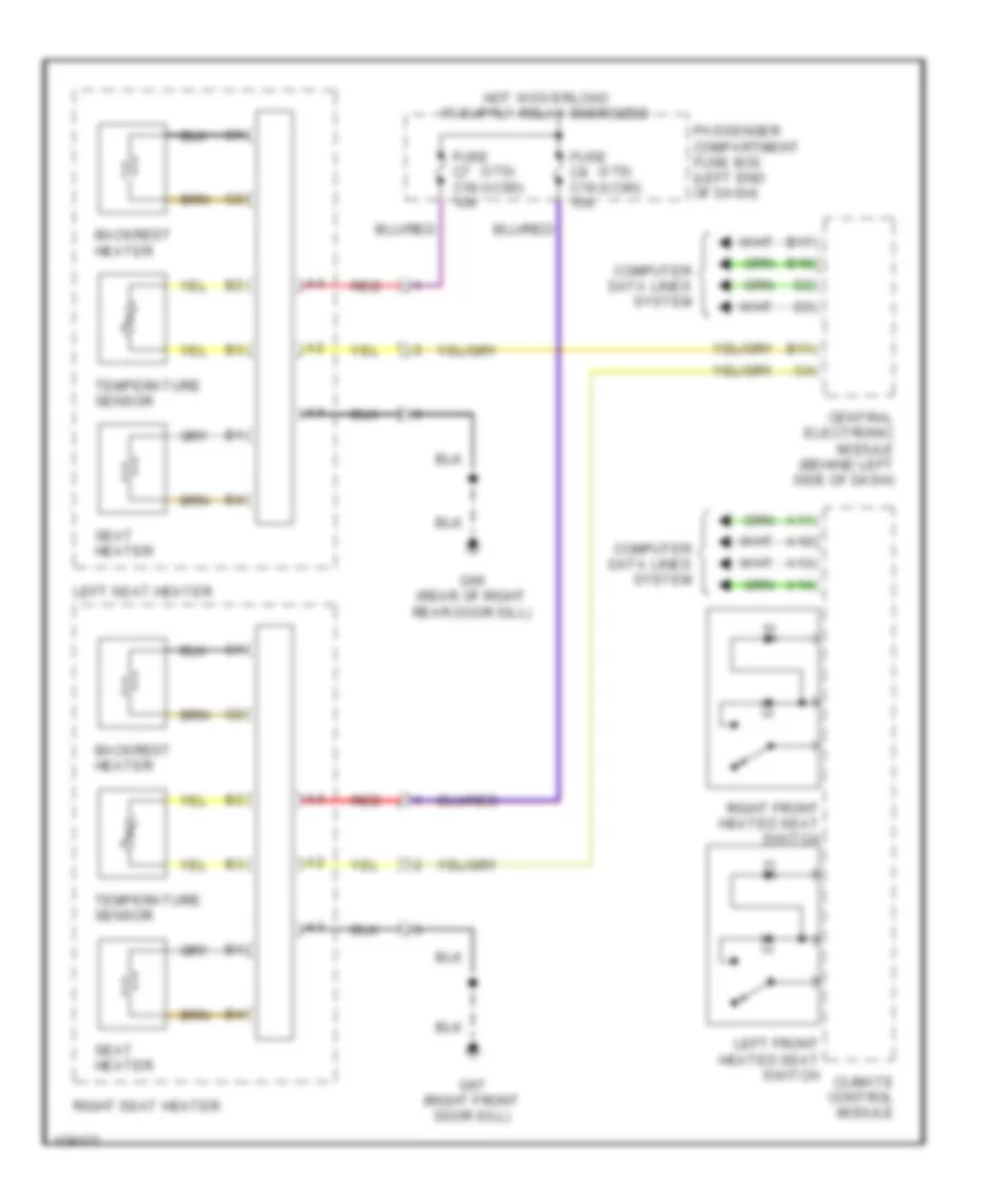
Электросхема подогрева сидений для Volvo V70 2003
Электросхема подогрева сидений для Volvo V70 2003 - Список элементов:
- (v70) (xc90)
- A11
- A12
- A13
- A14
- B11
- B17
- B18
- Backrest heater
- Central electronic module (behind left side of dash)
- Climate control module
- Computer data lines system
- Fuse c7 c18 15a
- Fuse c8 c19 15a
- G66 (rear of right rear door sill)
- G67 (right front door sill)
- Left front heated seat switch
- Left seat heater
- Passenger compartment fuse box (left end of dash)
- Red
- Right front heated seat switch
- Right seat heater
- Seat heater
- Temperature sensor
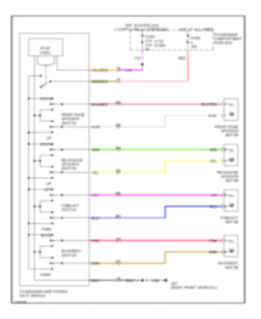
Электросхема привода пассажирского сиденья для Volvo V70 2003
Электросхема привода пассажирского сиденья для Volvo V70 2003 - Список элементов:
- (v70) (xc90)
- Aft
- Back
- Backrest motor
- Backrest switch
- Down
- Fore
- Fore/aft motor
- Fore/aft switch
- Forw
- Front edge up/down motor
- Front edge up/down switch
- Fuse 30a
- Fuse c14 c10 5a
- G67 (right front door sill)
- Hot at all times
- Passenger compartment fuse box
- Passenger side power seat module
- Pnk
- Rear edge up/down motor
- Rear edge up/down switch
- Red
- Stop logic
Стартер Генератор
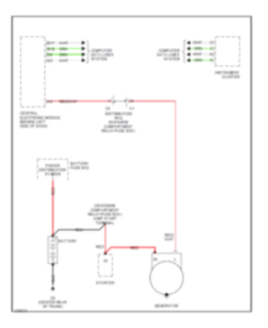
Электросхема Генератора для Volvo V70 2003
Электросхема Генератора для Volvo V70 2003 - Список элементов:
- (on engine compartment relay/fuse box) jump start terminal
- B17
- B18
- Battery
- Battery fuse box
- Central electronic module (behind left side of dash)
- Computer data lines system
- Distribution rail (in engine compartment relay/fuse box)
- G3 (center rear of trunk)
- Generator
- Instrument cluster
- Power distribution system
- Red
- Starter
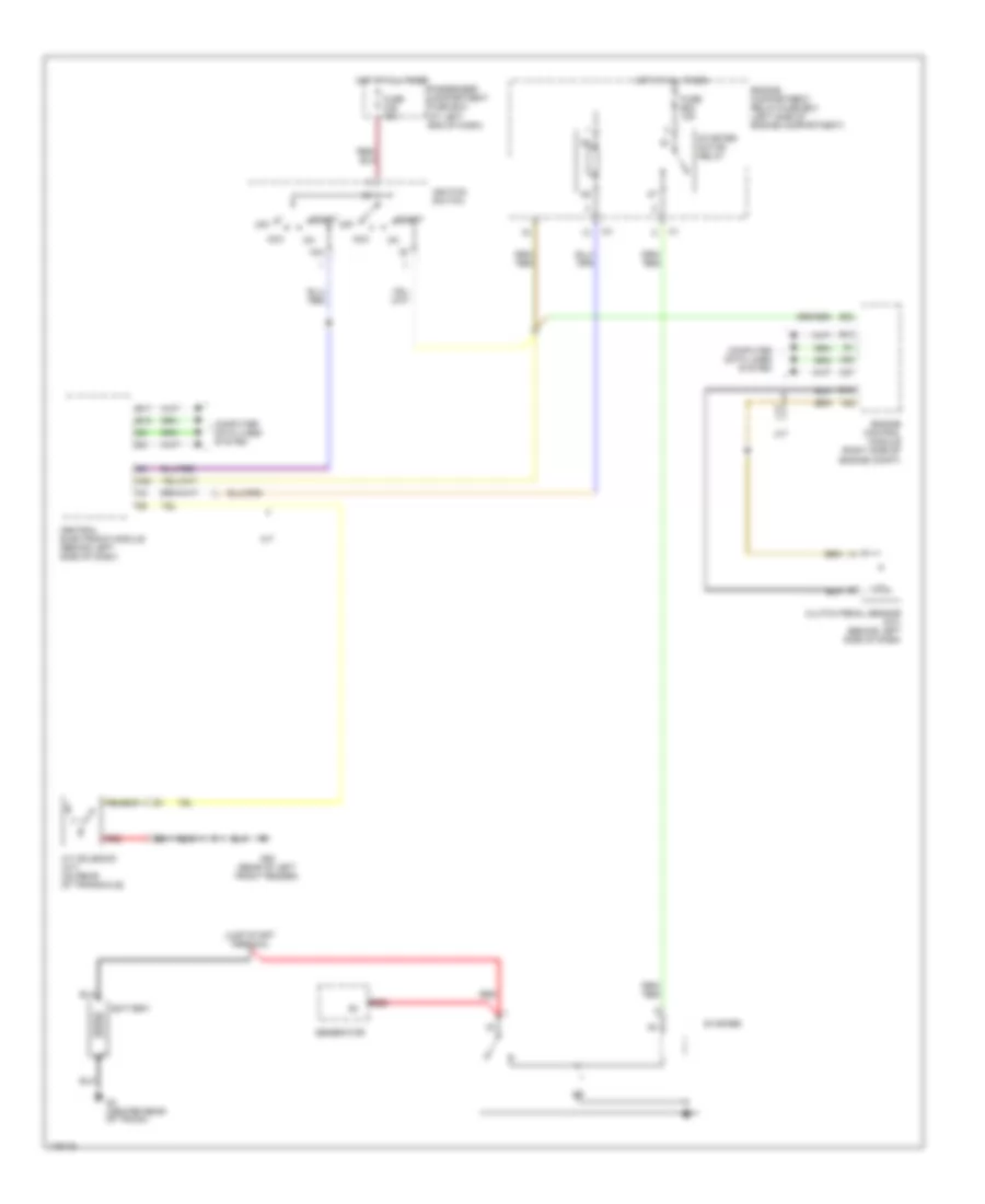
Электросхема стартера для Volvo V70 2003
Электросхема стартера для Volvo V70 2003 - Список элементов:
- 15a
- A/t
- A/t solenoid (a/t) (on rear of transaxle)
- A20
- A37
- A55
- Acc
- B13
- B15
- B17
- B18
- B23
- Battery
- Central electronic module (behind left side of dash)
- Clutch pedal sensor (m/t) (behind left side of dash)
- Computer data lines system
- Engine compartment relay/fuse box (left side of engine compartment)
- Engine control module (right side of engine compt)
- Fuse b22 15a
- Fuse c25 10a
- G3 (center rear of trunk)
- G93 (rear of left front fender)
- Generator
- Hot at all times
- Ignition switch
- Jump start terminal
- M/t
- Off
- Passenger compartment fuse box (at left end of dash)
- Red
- Start
- Starter
- Starter motor relay
Стеклоочистители и Стеклоомыватели Дворники
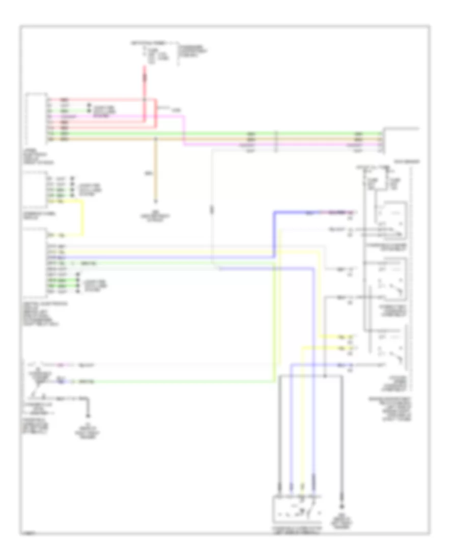
Электросхема передних стеклоочистителей дворников и омывателя лобового стекла для Volvo V70 2003
Электросхема передних стеклоочистителей дворников и омывателя лобового стекла для Volvo V70 2003 - Список элементов:
- (v70) (xc90)
- A13
- A14
- A16
- B15
- B16
- B17
- B18
- Central electronics module (behind left side of dash, on passenger compt relay box)
- Computer data lines system
- Engine compartment relay/fuse box (left side of engine compt, forward of strut tower)
- Fuse b13 25a
- Fuse b16 15a
- Fuse c28 c14 10a
- G1 (rear of right front fender)
- G93 (rear of left front fender)
- G98 (center front of roof)
- Hot at all times
- Intermittent windshield wiper relay
- Low/high speed windshield wiper relay
- Passenger compartment fuse box
- Rain sensor
- Red
- Steering wheel module
- Upper electronic module (front of roof)
- Washer fluid level monitor
- Windshield washer motor relay
- Windshield washer pump
- Windshield wiper motor (left side of firewall)
- Windshield wiper motor (on left side of firewall)
- Xc90
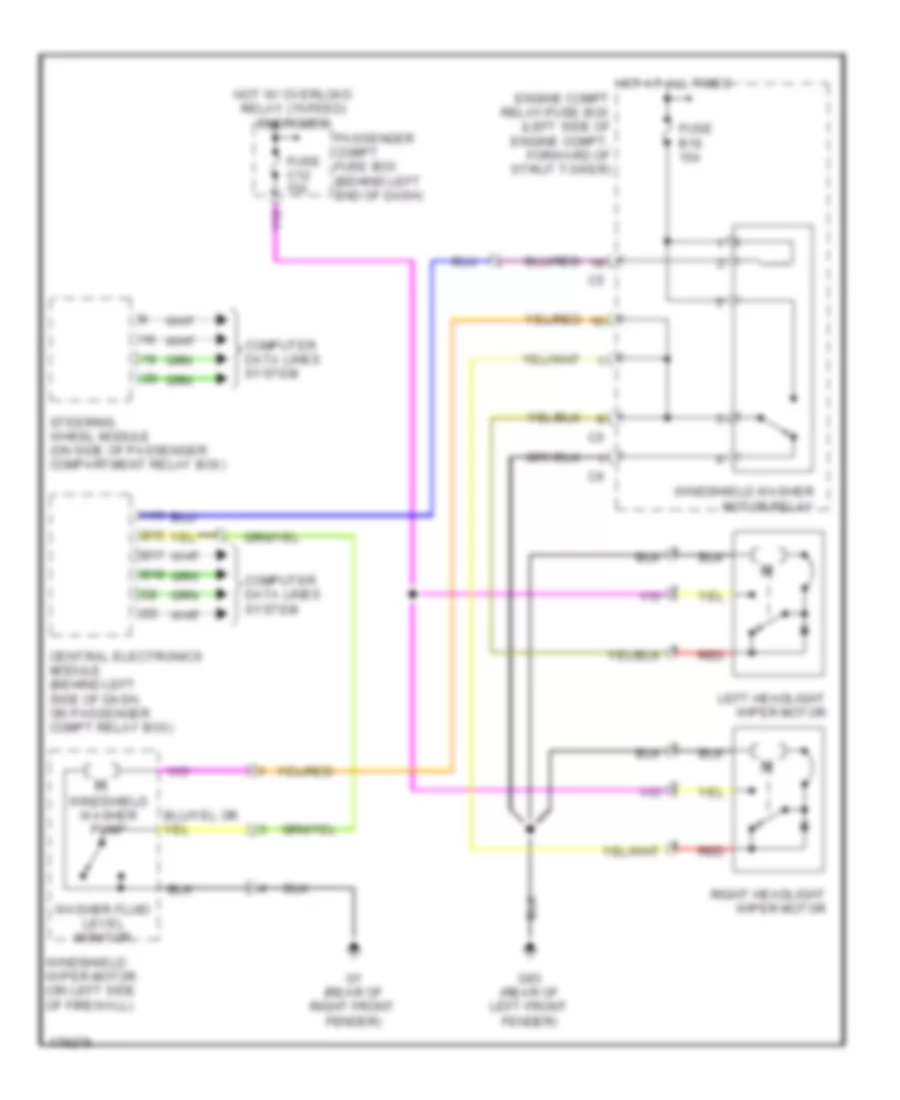
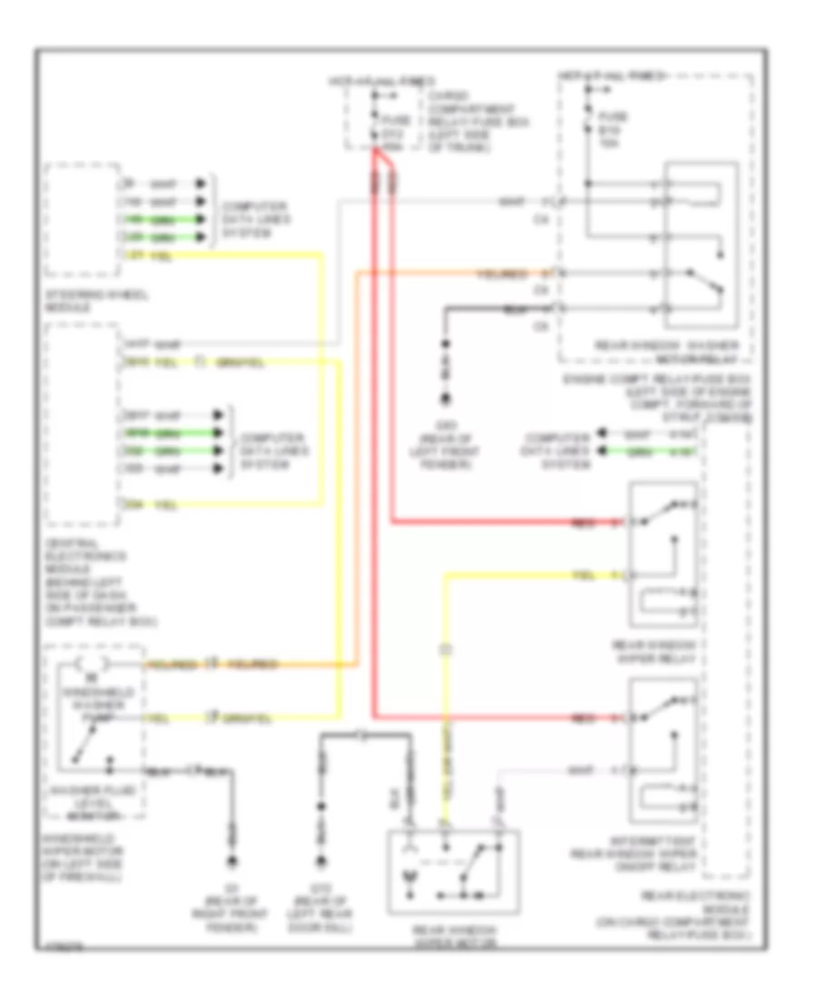
схема шайбы фары для Volvo V70 2003
схема шайбы фары для Volvo V70 2003 - Список элементов:
- A16
- B15
- B17
- B18
- Central electronics module (behind left side of dash, on passenger compt relay box)
- Computer data lines system
- Engine compt relay/fuse box (left side of engine compt, forward of strut tower)
- Fuse b16 15a
- Fuse c12 15a
- G1 (rear of right front fender)
- G93 (rear of left front fender)
- Hot at all times
- Hot w/ overload relay (15-feed) energized
- Left headlight wiper motor
- Passenger compt fuse box (behind left end of dash)
- Red
- Right headlight wiper motor
- Steering wheel module (on side of passenger compartment relay box)
- Washer fluid level monitor
- Windshield washer motor relay
- Windshield washer pump
- Windshield wiper motor (on left side of firewall)
Электросхема заднего стеклоочистителя дворника и омывателя для Volvo V70 2003
Электросхема заднего стеклоочистителя дворника и омывателя для Volvo V70 2003 - Список элементов:
- A14
- A16
- A17
- B15
- B17
- B18
- Cargo compartment relay/ fuse box (left side of trunk)
- Central electronics module (behind left side of dash, on passenger compt relay box)
- Computer data lines system
- Engine compt relay/fuse box (left side of engine compt, forward of strut tower)
- Fuse b10 10a
- Fuse d12 15a
- G1 (rear of right front fender)
- G72 (rear of left rear door sill)
- G93 (rear of left front fender)
- Hot at all times
- Intermittent rear window wiper on/off relay
- Rear electronic module (on cargo compartment relay/fuse box)
- Rear window washer motor relay
- Rear window wiper motor
- Rear window wiper relay
- Red
- Steering wheel module
- Washer fluid level monitor
- Windshield washer pump
- Windshield wiper motor (on left side of firewall)
ЦЕНТРАЛЬНЫЙ ЗАМОК
Электросхема центрального замка (1 из 2) для Volvo V70 2003
Электросхема центрального замка (1 из 2) для Volvo V70 2003 - Список элементов:
- A11
- A12
- A13
- A14
- A16
- B12
- Bll
- Cargo compartment relay/fuse box (at left side of trunk)
- Climate control module
- Combination instrument panel
- Computer data lines system
- Fuse c35 25a
- Fuse c36 25a
- Fuse c37 30a
- Fuse d6 10a
- Fuse d8 15a
- G66 (left front door sill)
- G67 (right front door sill)
- Hot at all times
- Key
- Left front door control module
- Left front door lock unit
- Lock
- Passenger compartment fuse box (at left end of dash)
- Pnk
- Power child lock switch
- Rear electronic module (at left side of trunk, on cargo compartment relay/fuse box)
- Red
- Right front door control module
- Right front door lock unit
- Trunk lid/ tailgate opening relay
- Trunk lid/ tailgate private lock switch
- Unlock
- Upper electronic module (on rearview mirror)
Электросхема центрального замка (2 из 2) для Volvo V70 2003
Электросхема центрального замка (2 из 2) для Volvo V70 2003 - Список элементов:
- (on passenger compartment relay box) central electronic module
- B12
- B13
- B17
- B18
- Bll
- C18
- Computer data lines system
- Fuel filler flap locking motor
- Fuel filler flap locking relay
- Fuel filler flap unlocking relay
- G48 (rear of right rear door sill)
- G66 (left front door sill)
- G67 (right front door sill)
- Left rear door deadlock relay
- Left rear door lock unit
- Left rear unlocking relay
- Pcl
- Pnk
- Rear door power window child lock relay
- Rear doors deadlock relay
- Rear electronic module (at left side of trunk, on cargo compartment relay/fuse box) box)
- Right rear door deadlock relay
- Right rear door lock unit
- Right rear unlocking relay
- Tailgate glass breakage sensor
- Tailgate lock module

 Čeština
 Dansk
Dansk Deutsch
 Ελληνικά
 English
 English
 Español
 Suomi
Suomi Français
 Français
 עברית
עברית Hrvatski
 Magyar
 Italiano
 日本語
日本語 한국어
한국어 Nederlands
 Polski
 Português
 Português
 Română
 Русский
 Slovenčina
 Slovenščina
 Türkçe
 中文 (中国)