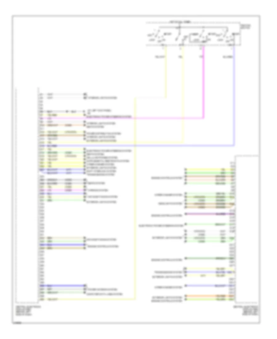
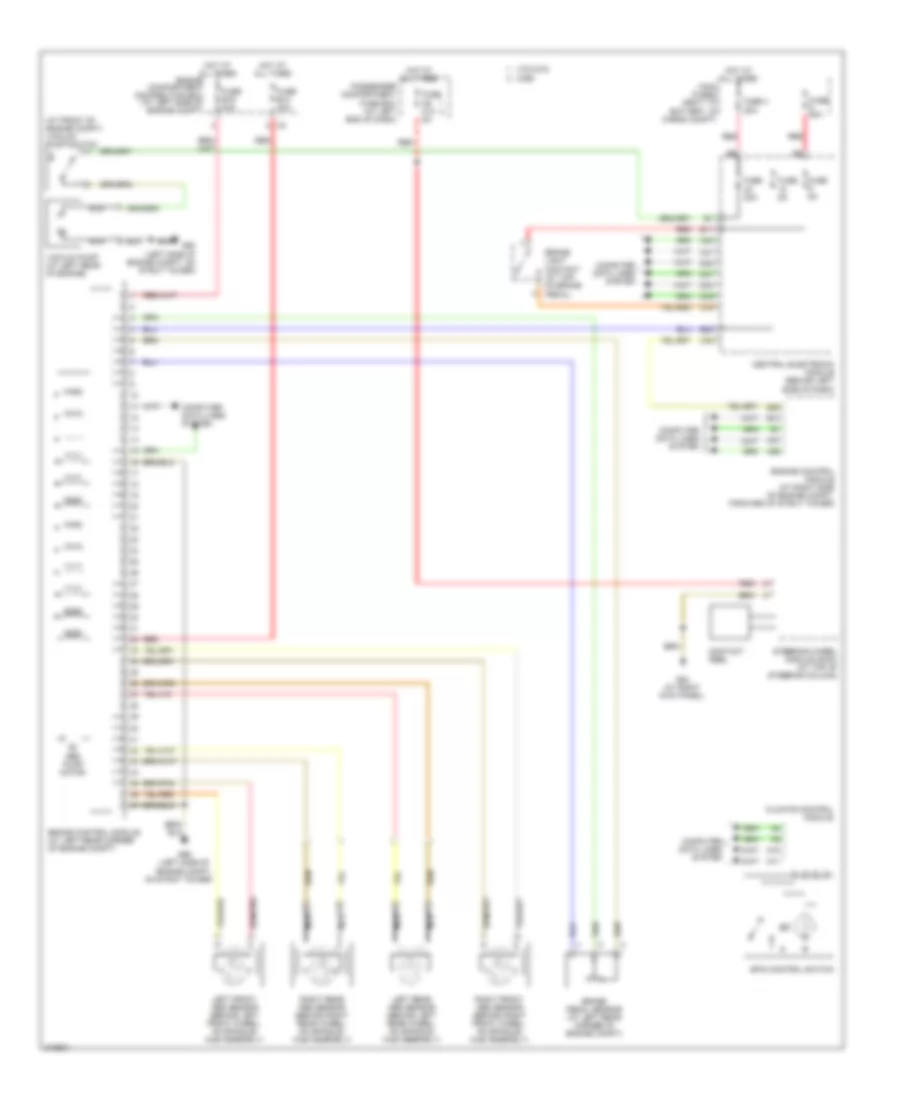
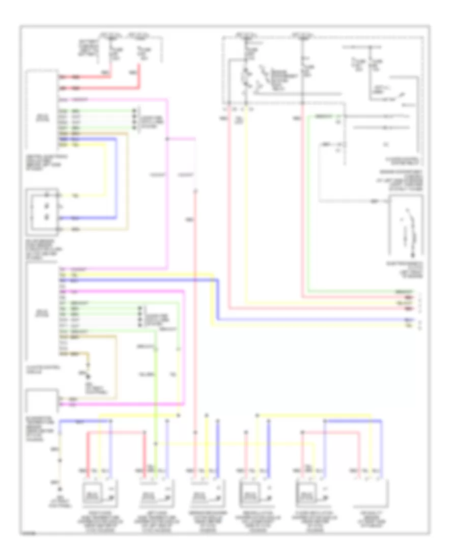
Автомтическая коробка Передач (АКПП) Полная привод (4WD) Блокировка Дифференциала
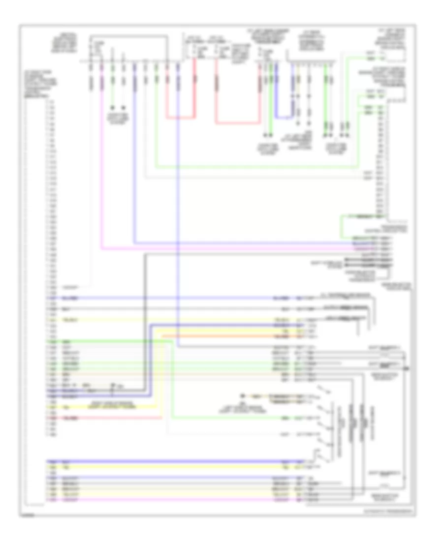
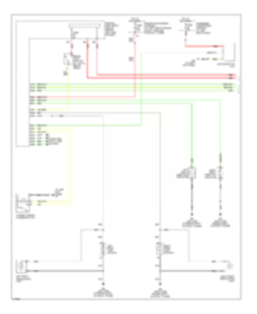
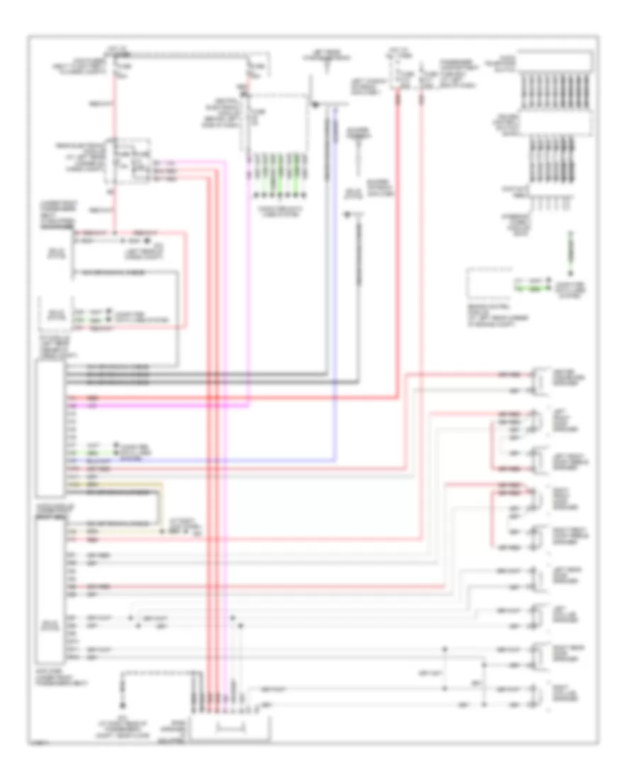
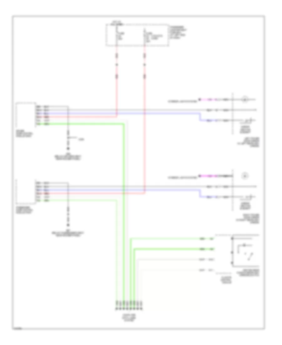
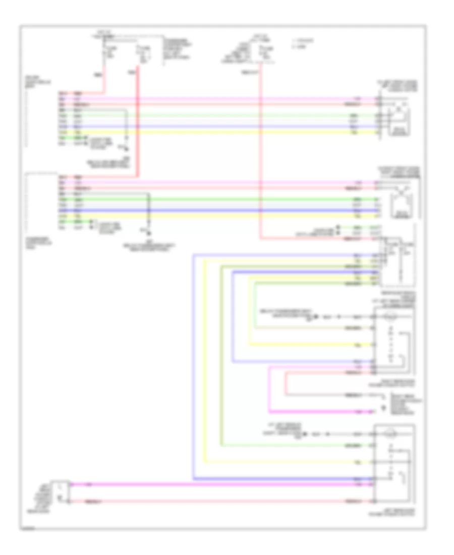
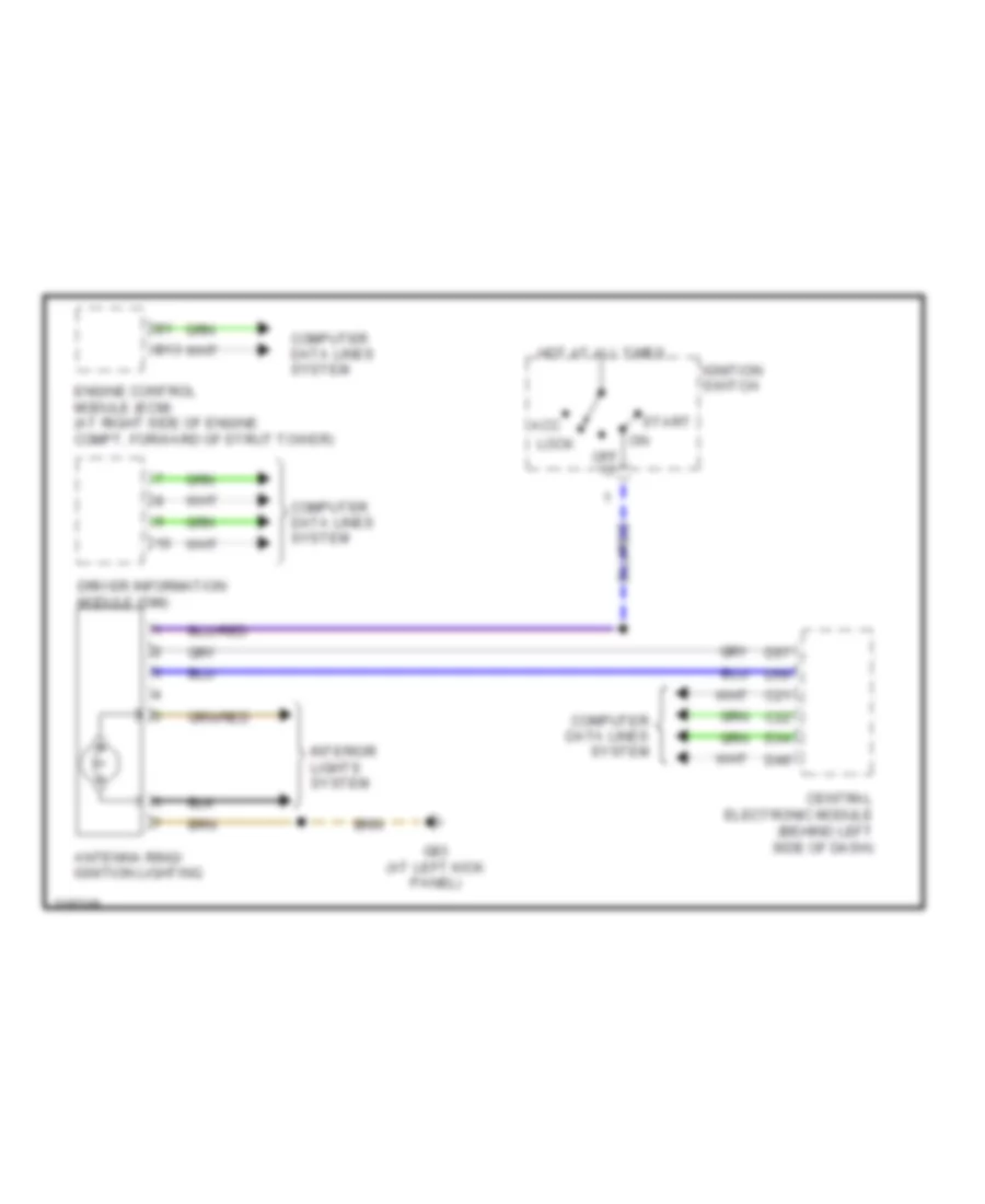
Электросхема коробки передач АКПП, AW55-50 для Volvo V70 T-5 2005
 https://portal-diagnostov.com/license.html
Automotive Electricians Portal FZCO
Automotive Electricians Portal FZCO
https://portal-diagnostov.com/license.html
https://portal-diagnostov.com/license.html
Automotive Electricians Portal FZCO
Automotive Electricians Portal FZCO
Электросхема коробки передач АКПП, AW55-50 для Volvo V70 T-5 2005 - Список элементов:
- (at left rear corner of cargo compt) rear electronic module (rem)
- (at left rear corner of engine compt)
- (at rear
- (at right side of engine compt, forward of strut tower) engine control module (ecm)
- (at right side of engine compt, forward of strut tower) transmission control module (tcm)
- (right side of engine compt, on strut tower)
- A10
- A11
- A12
- A13
- A14
- A15
- A16
- A17
- A18
- A19
- A20
- A21
- A22
- A23
- A24
- A25
- A26
- A27
- A28
- A29
- A30
- A31
- A32
- A33
- A34
- A35
- A36
- A37
- A38
- A39
- A40
- A41
- A42
- A43
- A44
- A45
- A46
- A47
- A48
- A49
- A50
- A51
- A52
- A53
- A54
- A55
- A56
- A57
- A58
- A59
- A60
- A61
- A62
- A63
- A64
- A65
- A66
- A67
- A68
- A69
- A70
- Automatic transmission
- B10
- B11
- B12
- B13
- B14
- B15
- B16
- B17
- B18
- B19
- B20
- B21
- Brake control module (bcm)
- C13
- C14
- C21
- C22
- C28
- Central electronic module (cem) (behind left side of dash)
- Computer data lines system
- D23
- D32
- D47
- Differential electronic module (dem)
- Differential)
- Fuse e1 60a
- Fuse e5 50a
- Fuse f21 10a
- Fuse f23 7.5a
- G46 (at left rear of passenger's compt, near floor)
- G93 (left side of engine compt, on strut tower)
- G94
- Gear selector contacts
- Gear selector module (gsm)
- Gear shifting solenoid 1
- Gear shifting solenoid 2
- Hot at all times
- Input speed sensor
- Lock-up solenoid
- Main fuse (next to battery, in cargo compt)
- Mode selector automatic transmission
- Nc1+
- Nc1-
- Nca
- Oil temperature sensor
- Otg
- Output speed sensor
- Pressure solenoid
- Red
- Shift interlock system
- Shift solenoid 3
- Shift solenoid 4
- Shift solenoid 5
- Sls
- Slsg
- Slt
- Sltg
- Slu
- Slug
- Sp+
- Sp-
- St+
- St-
- Throttle solenoid
- Transmission control module (tcm)
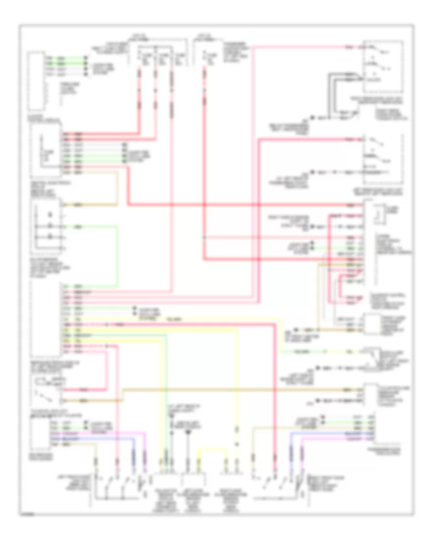
БЛОК ПРЕДОХРАНИТЕЛЕЙ И РЕЛЕ
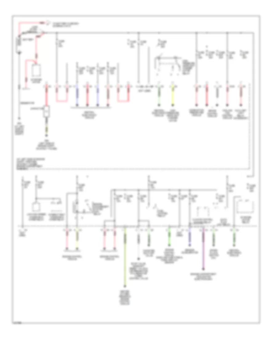
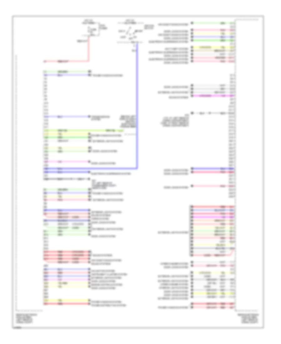
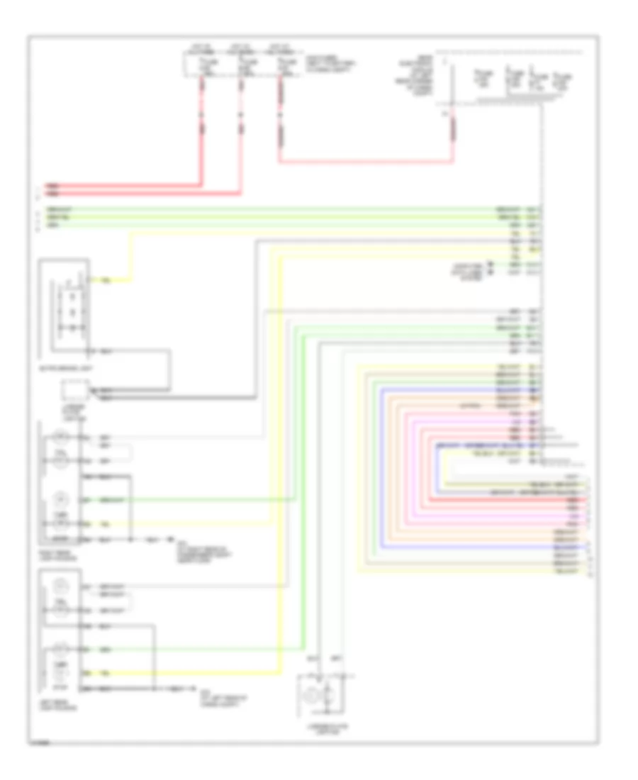
Электросхема блока предохранителей и реле (1 из 2) для Volvo V70 T-5 2005
 https://portal-diagnostov.com/license.html
Automotive Electricians Portal FZCO
Automotive Electricians Portal FZCO
https://portal-diagnostov.com/license.html
https://portal-diagnostov.com/license.html
Automotive Electricians Portal FZCO
Automotive Electricians Portal FZCOЭлектросхема блока предохранителей и реле (1 из 2) для Volvo V70 T-5 2005 - Список элементов:
- (at left side of engine compt)
- (at left side of engine compt, forward of strut tower) engine compartment fuse box
- (left side of engine compt, on strut tower)
- (not used)
- 15/30
- Auxiliary light relay (accessory)
- Battery
- Brake control module
- Canister shut-off valve
- Capacitor
- Central electronic module
- Climate control system relay
- Combustion preheater module
- Cooling fan control module
- Engine compartment cooling fan electrics box
- Engine control module
- Engine control module, gasoline injectors & mass airflow sensor
- Engine management system main relay
- Evap valve, camshaft reset valve & air preheating ptc resistor turbo control valve
- Fuel system relay
- Fuse a1 60a
- Fuse a2 40a
- Fuse a3 40a
- Fuse a4
- Fuse a8 60a
- Fuse b1 25a
- Fuse b11 20a
- Fuse b12 5a
- Fuse b13 25a
- Fuse b14 30a
- Fuse b15 35a
- Fuse b17 20a
- Fuse b18 15a
- Fuse b19 30a
- Fuse b2 20a
- Fuse b20 20a
- Fuse b21 15a
- Fuse b22 35a
- Fuse b23 10a
- Fuse b3 10a
- Fuse b4 20a
- Fuse b5 10a
- Fuse b6 15a
- Fuse b7
- Fuse b8 10a
- Fuse b9 10a
- G53
- G93
- Generator
- Glow plug unit relay
- Heated oxygen sensor & engine control module
- High pressure headlight washer motor
- High pressure headlight washer motor relay
- Intermittent windshield wiper relay
- Jump start terminal
- Low/high speed windshield wiper relay
- Red
- Sensor accelerator
- Spark plug & ignition coil
- Starter motor
- Starter motor relay
- To battery fuse box (diagram 2 of 2)
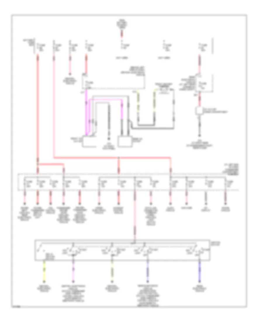
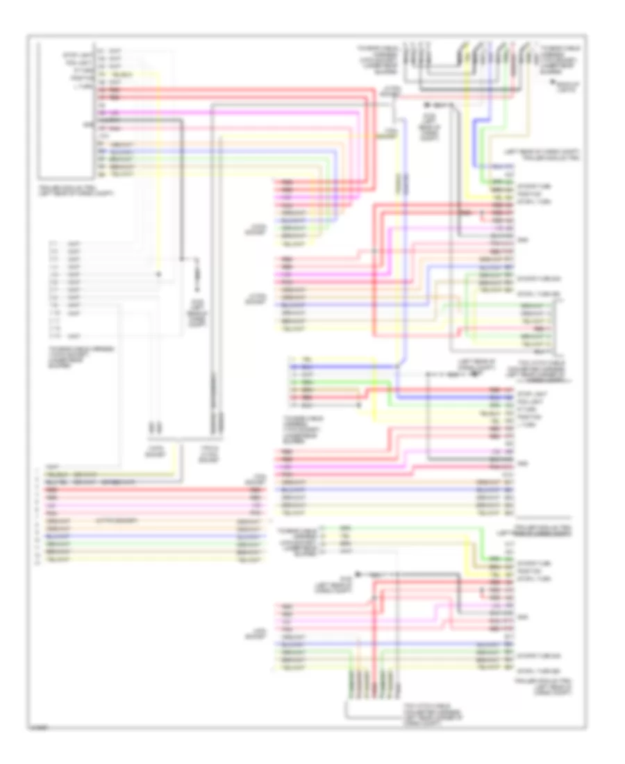
Электросхема блока предохранителей и реле (2 из 2) для Volvo V70 T-5 2005
 https://portal-diagnostov.com/license.html
Automotive Electricians Portal FZCO
Automotive Electricians Portal FZCO
https://portal-diagnostov.com/license.html
https://portal-diagnostov.com/license.html
Automotive Electricians Portal FZCO
Automotive Electricians Portal FZCOЭлектросхема блока предохранителей и реле (2 из 2) для Volvo V70 T-5 2005 - Список элементов:
- (at left end of dash) passenger compartment fuse box
- (behind left side of dash) central electronic module
- (not used)
- (suspension module)
- (v70)
- 12v outlet cargo compartment
- A red
- A17
- Acc
- Amplifier
- Audio module
- B31
- Battery fuse box
- Central electronic module
- D12
- Data link connector, steering wheel module & light switch module
- Driver/ passenger door module & central electronic module
- Fan control module
- From battery (diagram 1 of 2)
- Front 12v outlet
- Front ashtray lighting
- Fuse 15a
- Fuse c1 25a
- Fuse c10 20a
- Fuse c11 30a
- Fuse c12 10a
- Fuse c13 5a
- Fuse c2 25a
- Fuse c3 30a
- Fuse c4 25a
- Fuse c5 25a
- Fuse c6 10a
- Fuse c7 15a
- Fuse c8 7.5a
- Fuse c9 5a
- Fuse e1 60a
- Fuse e2 40a
- Fuse e3
- Fuse e4 50a
- Fuse e5 50a
- Fuse e6 50a
- Fuse e7 50a
- G10 (at right kick panel)
- G73 (at right rear of passenger's compt, near floor)
- Ignition switch
- Key in ignition switch
- Lock
- Nca
- Off
- Passenger/ driver door module & central electronic module
- Phone module
- Power passenger seat & switch unit
- Power seat module & rear electronic module
- Rear 12v outlet
- Rear electronic module
- Rear electronic module (at left rear corner of cargo compt)
- Red
- Rti display
- Start
- Sunroof control module
- Upper electronic module
БЛОКИ УПРАВЛЕНИЯ КУЗОВОМ
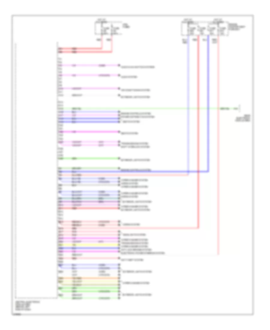
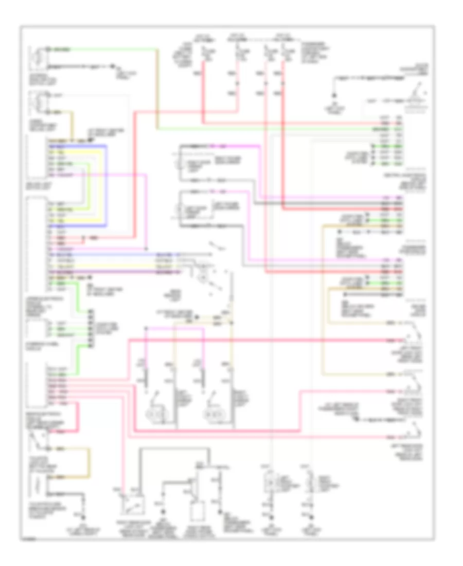
центральная электронная схема модуля (1 из 2) для Volvo V70 T-5 2005
 https://portal-diagnostov.com/license.html
Automotive Electricians Portal FZCO
Automotive Electricians Portal FZCO
https://portal-diagnostov.com/license.html
https://portal-diagnostov.com/license.html
Automotive Electricians Portal FZCO
Automotive Electricians Portal FZCOцентральная электронная схема модуля (1 из 2) для Volvo V70 T-5 2005 - Список элементов:
- (a/t)
- (drl)
- (m/t)
- (v70/xc70)
- (xc90)
- A10
- A11
- A12
- A13
- A14
- A15
- A16
- A17
- A18
- A19
- A20
- A21
- A22
- A23
- A24
- A25
- A26
- A27
- A28
- A29
- Air conditioning system
- Anti-lock brakes system
- Anti-theft system
- Audio & navigation systems
- Audio system
- B10
- B11
- B12
- B13
- B14
- B15
- B16
- B17
- B18
- B19
- B20
- B21
- B22
- B23
- B24
- B25
- B26
- B27
- B28
- B29
- B30
- B31
- B32
- Central electronic module (cem) (behind left side of dash)
- Electronic power steering system
- Engine compartment fuse box
- Engine controls system
- Exterior lights system
- Fuse b17 20a
- Fuse b18 15a
- Fuse b20 20a
- Fuse b21 15a
- Fuse e4 50a
- Fuse e5 50a
- Headlights system
- Horns system
- Hot at all times
- Main fuses
- Pnk
- Power distribution system
- Rear electronic module (rem)
- Red
- Seats system
- Shift interlock system
- Transmissions system
- Wiper/washer system
центральная электронная схема модуля (2 из 2) для Volvo V70 T-5 2005
 https://portal-diagnostov.com/license.html
Automotive Electricians Portal FZCO
Automotive Electricians Portal FZCO
https://portal-diagnostov.com/license.html
https://portal-diagnostov.com/license.html
Automotive Electricians Portal FZCO
Automotive Electricians Portal FZCOцентральная электронная схема модуля (2 из 2) для Volvo V70 T-5 2005 - Список элементов:
- (a/t)
- (at left kick panel)
- (m/t)
- (v70/xc70)
- (xc90)
- 15a
- Acc
- Air conditioning system
- C10
- C11
- C12
- C13
- C14
- C15
- C16
- C17
- C18
- C19
- C20
- C21
- C22
- C23
- C24
- C25
- C26
- C27
- C28
- C29
- C30
- C31
- C32
- C33
- C34
- C35
- Cellular phones system
- Central electronic module (cem) (behind left side of dash)
- Computer data lines system
- D10
- D11
- D12
- D13
- D14
- D15
- D16
- D17
- D18
- D19
- D20
- D21
- D22
- D23
- D24
- D25
- D26
- D27
- D28
- D29
- D30
- D31
- D32
- D33
- D34
- D35
- D36
- D37
- D38
- D39
- D40
- D41
- D42
- D43
- D44
- D45
- D46
- D47
- D48
- D49
- D50
- D51
- D52
- D53
- D54
- D55
- D56
- D57
- D58
- D59
- D60
- Electronic power steering system
- Engine controls system
- Exterior lights system
- Headlights system
- Hot at all times
- Ignition switch
- Interior lights system
- Key in
- Lock
- Off
- Power antenna system
- Power distribution system
- Seats system
- Shift interlock system
- Start
- Transmissions system
- Warning system
- Wiper/washer system
задняя электронная схема модуля для Volvo V70 T-5 2005
 https://portal-diagnostov.com/license.html
Automotive Electricians Portal FZCO
Automotive Electricians Portal FZCO
https://portal-diagnostov.com/license.html
https://portal-diagnostov.com/license.html
Automotive Electricians Portal FZCO
Automotive Electricians Portal FZCOзадняя электронная схема модуля для Volvo V70 T-5 2005 - Список элементов:
- (behind left side of dash) central electronic module (cem)
- (v70/xc70)
- (xc90)
- 15l
- A10
- A11
- A12
- A13
- A14
- A15
- A16
- A17
- A18
- A19
- A20
- A21
- A22
- A23
- A24
- A25
- A26
- A27
- A28
- A29
- A30
- A31
- A32
- Acc
- Air conditioning system
- Anti-theft system
- B10
- B11
- B12
- B13
- B14
- B15
- B16
- B17
- B18
- B19
- B20
- B21
- B22
- B23
- B24
- B25
- B26
- B27
- B28
- B29
- B30
- B31
- C10
- C11
- C12
- D10
- D11
- D12
- D13
- D14
- D15
- D16
- D17
- D18
- D19
- D20
- D21
- D22
- D23
- D24
- D25
- D26
- D27
- D28
- D29
- D30
- D31
- D32
- D33
- D34
- D35
- D36
- Door locks system
- Electronic suspension system
- Engine controls system
- Exterior lights system
- F10
- Fuse e1 60a
- G47 (at left rear of passenger's compt, near floor)
- G72 (v70: at left rear of cargo compartment) (xc90: at right rear of cargo compartment)
- Horns system
- Hot at all times
- Ignition switch
- Instrument cluster system
- Interior lights system
- Lock
- Main fuses
- Module (rem) (left rear of cargo compt)
- Navigation system
- Off
- Pnk
- Power distribution system
- Power windows system
- Rear electronic
- Rear electronic module (rem) (left rear of cargo compt)
- Red
- Sound systems
- Start
- Transmissions system
- Wiper/washer system
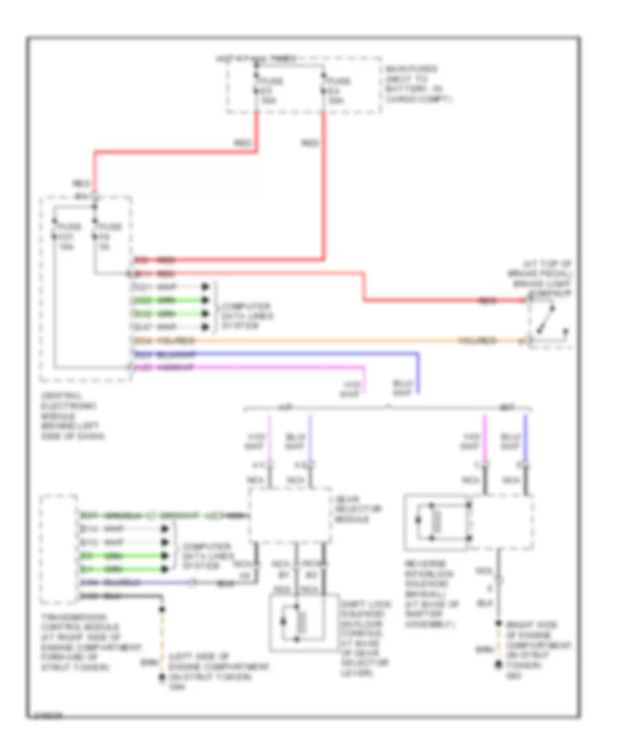
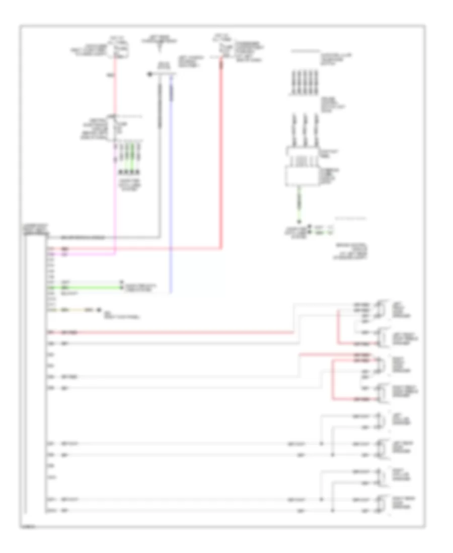
БЛОКИРОВКИ СЕЛЕКТОРА СТОЯНОЧНЫЙ ТОРМОЗ
Электросхема блокировки селектора для Volvo V70 T-5 2005
 https://portal-diagnostov.com/license.html
Automotive Electricians Portal FZCO
Automotive Electricians Portal FZCO
https://portal-diagnostov.com/license.html
https://portal-diagnostov.com/license.html
Automotive Electricians Portal FZCO
Automotive Electricians Portal FZCOЭлектросхема блокировки селектора для Volvo V70 T-5 2005 - Список элементов:
- (at top of brake pedal) brake light contact
- (left side of engine compartment, on strut tower) g94
- (right side of engine compartment, on strut tower) g93
- A/t
- A25
- A53
- A54
- B11
- B13
- B14
- B21
- C21
- C22
- C34
- Central electronic module (behind left side of dash)
- Computer data lines system
- D23
- D32
- D47
- Fuse e4 50a
- Fuse e5 50a
- Fuse f21 10a
- Fuse f9 5a
- Gear selector module
- Hot at all times
- M/t
- Main fuses (next to battery, in cargo compt)
- Nca
- Red
- Reverse interlock solenoid (manual) (at base of shifter assembly)
- Shift lock solenoid (in floor console, at base of gear selector lever)
- Transmission control module (at right side of engine compartment, forward of strut tower)
ВНЕШНЕЕ ОСВЕЩЕНИЕ
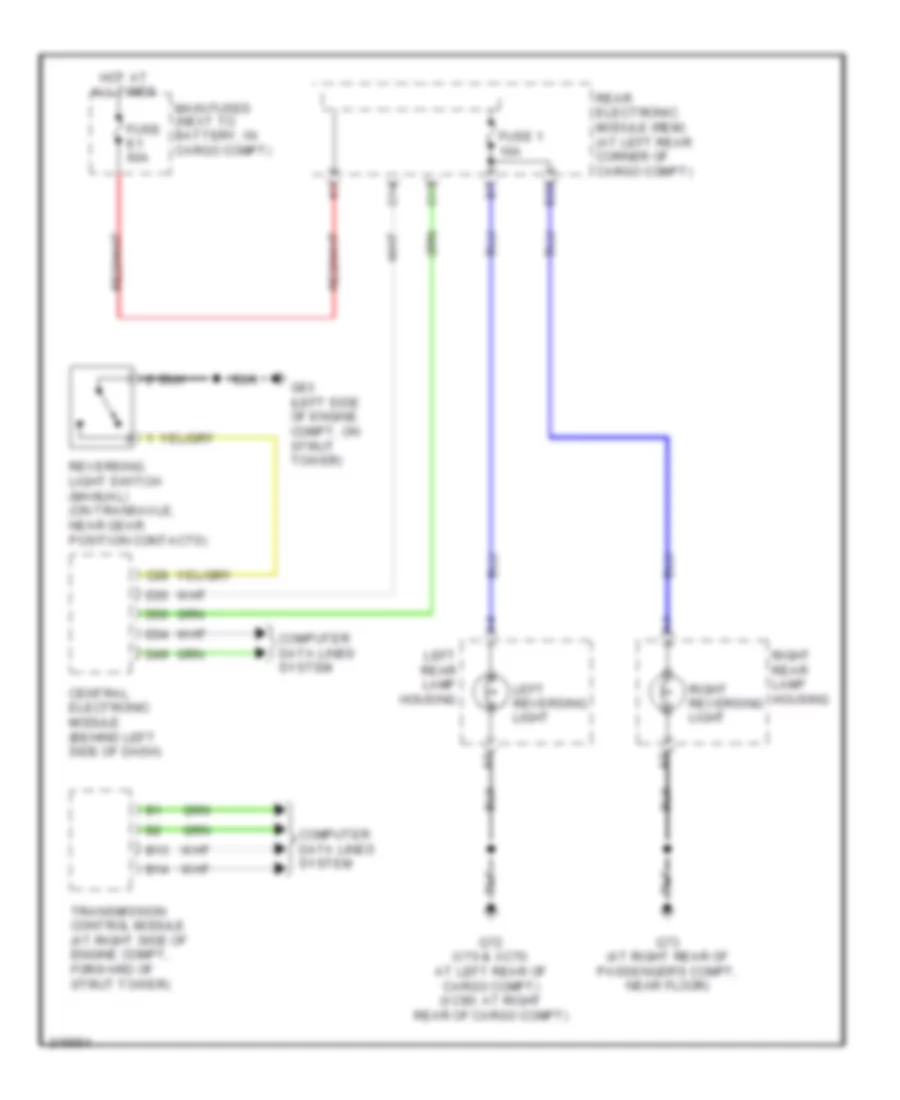
Электросхема заднего хода для Volvo V70 T-5 2005
 https://portal-diagnostov.com/license.html
Automotive Electricians Portal FZCO
Automotive Electricians Portal FZCO
https://portal-diagnostov.com/license.html
https://portal-diagnostov.com/license.html
Automotive Electricians Portal FZCO
Automotive Electricians Portal FZCOЭлектросхема заднего хода для Volvo V70 T-5 2005 - Список элементов:
- B13
- B14
- B23
- C13
- C14
- C28
- Central electronic module (behind left side of dash)
- Computer data lines system
- D34
- D35
- D49
- D50
- Fuse 1 10a
- Fuse e1 60a
- G72 (v70 & xc70: at left rear of cargo compt) (xc90: at right rear of cargo compt)
- G73 (at right rear of passenger's compt, near floor)
- G93 (left side of engine compt, on strut tower)
- Hot at all times
- Left rear lamp housing
- Left reversing light
- Main fuses (next to battery, in cargo compt)
- Rear electronic module (rem) (at left rear corner of cargo compt)
- Reversing light switch (manual) (on transaxle, near gear position contacts)
- Right rear lamp housing
- Right reversing light
- Transmission control module (at right side of engine compt, forward of strut tower)
Электросхема внешнего освещения (1 из 3) для Volvo V70 T-5 2005
 https://portal-diagnostov.com/license.html
Automotive Electricians Portal FZCO
Automotive Electricians Portal FZCO
https://portal-diagnostov.com/license.html
https://portal-diagnostov.com/license.html
Automotive Electricians Portal FZCO
Automotive Electricians Portal FZCOЭлектросхема внешнего освещения (1 из 3) для Volvo V70 T-5 2005 - Список элементов:
- (at left kick panel) g6
- (left side of engine compt, on strut tower)
- A12
- A15
- A29
- B11
- B24
- B31
- B32
- Brake light contact (at top of brake pedal)
- C19
- C20
- C34
- Central electronic module (behind left side of dash)
- Computer data lines system
- D14
- D22
- D34
- D35
- D41
- D49
- D50
- Engine compartment fuse box (at left side of engine compt, forward of strut tower)
- Fuse b18 15a
- Fuse c9 5a
- Fuse f9 5a
- G84 (at right kick panel)
- G93
- G93 (left side of engine compt, on strut tower)
- G94 (right side engine compt, on strut tower)
- Hazard warning flasher switch
- Hot at all times
- Left front direction indicator
- Left front lamp housing
- Left front side running light
- Lighting switch unit
- Passenger compartment fuse box (at left end of dash)
- Red
- Right front direction indicator
- Right front lamp housing
- Right front side running light
Электросхема внешнего освещения (2 из 3) для Volvo V70 T-5 2005
 https://portal-diagnostov.com/license.html
Automotive Electricians Portal FZCO
Automotive Electricians Portal FZCO
https://portal-diagnostov.com/license.html
https://portal-diagnostov.com/license.html
Automotive Electricians Portal FZCO
Automotive Electricians Portal FZCOЭлектросхема внешнего освещения (2 из 3) для Volvo V70 T-5 2005 - Список элементов:
- (4/7-pin)
- A18
- A20
- A21
- B10
- B11
- C13
- C14
- Computer data lines system
- Extra brake light
- F10
- Fuse e1 60a
- Fuse e4 50a
- Fuse e5 50a
- Fuse f20 20a
- Fuse f29 25a
- Fuse f30 25a
- Fuse f7 15a
- G72 (at left rear of cargo compt)
- G73 (at right rear of passenger's compt near floor)
- Hot at all times
- Left rear lamp housing
- License plate lighting
- Main fuses (next to battery, in cargo compt)
- Pnk
- Rear electronic module (at left rear corner of cargo compt)
- Red
- Right rear lamp housing
- Stop
- Tail
- Turn
Электросхема внешнего освещения (3 из 3) для Volvo V70 T-5 2005
 https://portal-diagnostov.com/license.html
Automotive Electricians Portal FZCO
Automotive Electricians Portal FZCO
https://portal-diagnostov.com/license.html
https://portal-diagnostov.com/license.html
Automotive Electricians Portal FZCO
Automotive Electricians Portal FZCOЭлектросхема внешнего освещения (3 из 3) для Volvo V70 T-5 2005 - Список элементов:
- (4/7-pin socket)
- (7-pin socket) (under rear bumper)
- (left rear of cargo compt) g120
- (left rear of cargo compt) trailer module (trm)
- 13-pin socket
- 4-pin socket
- 4/7-pin socket
- 7-pin & 4/7-pin socket
- 7-pin socket
- A10
- A11
- A12
- Back-up lights
- Fog light
- G120 (left rear of cargo compt)
- Gnd
- L turn
- Nca
- Pnk
- Position
- R turn
- Red
- Stop light
- Stop/l turn
- Stop/l turn sig
- Stop/r turn
- Stop/r turn sig
- Tow hitch cable converter harness (left rear corner of cargo compt)
- Towbar cable harness (13-pin socket) (under rear bumper)
- Towbar cable harness (4-pin socket) (under rear bumper)
- Towbar cable harness (7-pin socket) (under rear bumper)
- Trailer module (trm) (left rear of cargo compt)
ВНУТРЕННЕЕ ОСВЕЩЕНИЕ
Электросхема подсветки для Volvo V70 T-5 2005
 https://portal-diagnostov.com/license.html
Automotive Electricians Portal FZCO
Automotive Electricians Portal FZCO
https://portal-diagnostov.com/license.html
https://portal-diagnostov.com/license.html
Automotive Electricians Portal FZCO
Automotive Electricians Portal FZCOЭлектросхема подсветки для Volvo V70 T-5 2005 - Список элементов:
- pnk
- (at front center of headliner) g98
- (at left rear of passenger's compt near floor) g46
- A10
- Antenna ring/ ignition switch light
- B10
- B12
- C12
- C13
- C14
- Cargo compartment ceiling light
- Ceiling light switch unit
- Central electronic module (behind left side of dash)
- Computer data lines system
- D13
- D29
- D33
- D34
- D35
- D49
- D50
- Driver door module
- Fuse c4 25a
- Fuse c5 25a
- Fuse c6 10a
- Fuse e4 50a
- G6 (left kick panel)
- G66 (below driver's seat near rocker panel)
- G67 (below passenger's seat near rocker panel)
- G72 (at left rear of cargo compt)
- G98 (at front center of headliner)
- Glove compartment light
- Hot at all times
- Left door mirror light
- Left front courtesy light
- Left front door lock unit (rear left front door)
- Left power door mirror
- Left rear door lock unit (rear of left rear door)
- Left vanity mirror light
- Main fuses (next to battery, in cargo compt)
- Nca
- Passenger compartment fuse box (at left end of dash)
- Passenger door module
- Pnk
- Rear electronic module (left rear corner of cargo compt)
- Rear reading light
- Red
- Right door mirror light
- Right front courtesy light
- Right front door lock unit (rear of right front door)
- Right power door mirror
- Right rear door lock unit (rear of right rear door)
- Right rear door/ power window switch
- Right vanity mirror light
- Steering wheel module
- Tailgate glass breakage sensor (in tailgate window)
- Tailgate lock unit (bottom rear of tailgate)
- Upper electronic module (integral to rearview mirror)
- W/ pcl
- W/o pcl
Электросхема подсветки приборов для Volvo V70 T-5 2005
 https://portal-diagnostov.com/license.html
Automotive Electricians Portal FZCO
Automotive Electricians Portal FZCO
https://portal-diagnostov.com/license.html
https://portal-diagnostov.com/license.html
Automotive Electricians Portal FZCO
Automotive Electricians Portal FZCOЭлектросхема подсветки приборов для Volvo V70 T-5 2005 - Список элементов:
- (at right kick panel) g84
- (v70,xc70) (xc90)
- A10
- A11
- A16
- A19
- Audio module (v70, xc70) (under right front seat)
- Audio/cellular telephone switch
- B30
- Ceiling light switch unit
- Central electronic module (behind left side of dash)
- Child safety lock switch (pcl)
- Climate control module
- Computer data lines system
- Contact reel (top of steering column)
- Cruise control switch unit
- D34
- D35
- D41
- D49
- D50
- Driver information module
- Extra lights switch
- Fuse c9 c10 5a
- Fuse e1 60a
- Fuse e4 50a
- Fuse f10 20a
- Fuse f9 20a
- G46 (at left rear of passenger's compt near floor)
- G67 (below passenger's seat near rocker panel)
- G84 (at right kick panel)
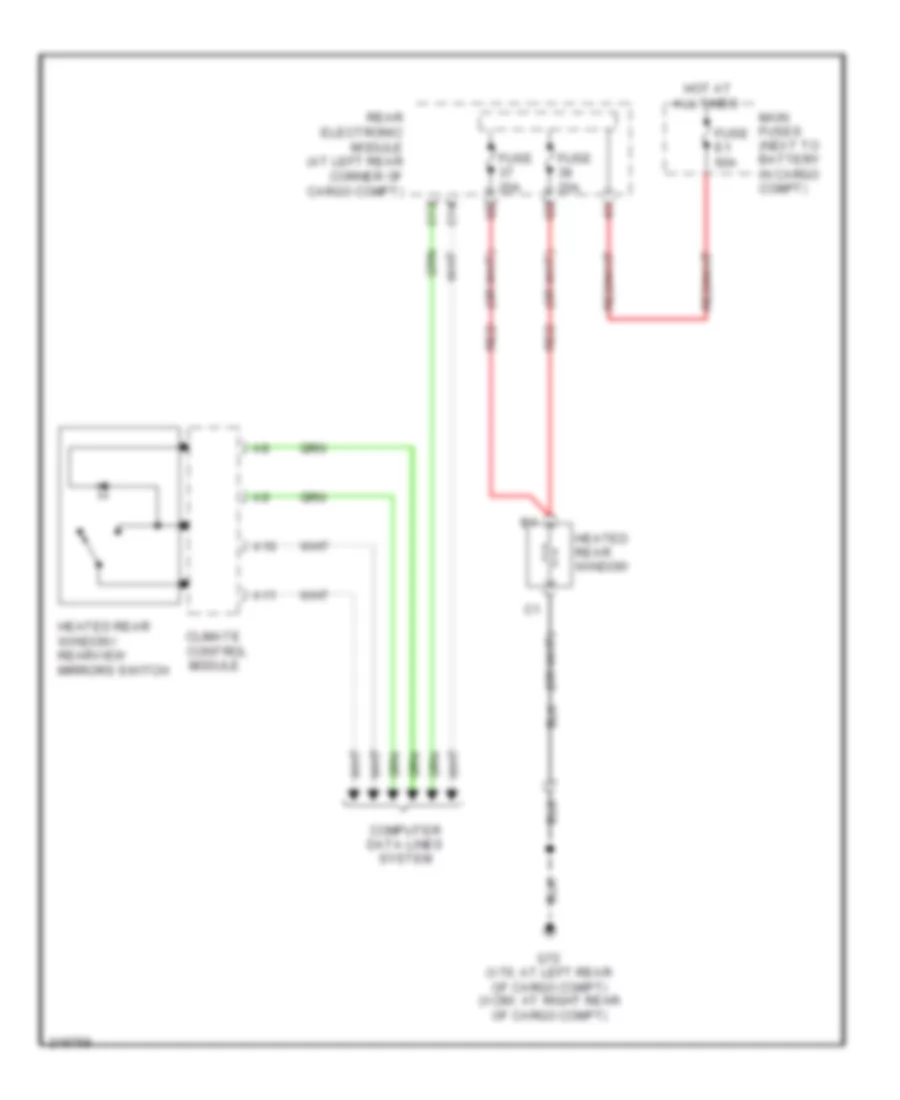
- Heated rear window/rearview mirrors switch
- Hot at all times
- Left heated seat switch
- Left rear door power window switch
- Light switch module
- Main fuses (next to battery, in cargo compartment)
- Nca
- Passenger compartment fuse box (at left end of dash)
- Power sunroof switch
- Rear electronic module (at left rear corner of cargo compt)
- Red
- Reduced alarm switch
- Retractable rearview mirrors switch
- Right heated seat switch
- Right rear door power window switch
- Spin control switch
- Steering wheel module
- Sunroof control module (forward of sun roof opening)
- Tailgate private locking switch
- Upper electronic module (v70/xc70: integral to rearview mirror) (xc90: rearward of roof console)
ЗАЗЕМЛЕНИЕ ПОДКЛЮЧЕНИЕ МАССЫ
Электросхема подключение массы заземления (1 из 2) для Volvo V70 T-5 2005
 https://portal-diagnostov.com/license.html
Automotive Electricians Portal FZCO
Automotive Electricians Portal FZCO
https://portal-diagnostov.com/license.html
https://portal-diagnostov.com/license.html
Automotive Electricians Portal FZCO
Automotive Electricians Portal FZCOЭлектросхема подключение массы заземления (1 из 2) для Volvo V70 T-5 2005 - Список элементов:
- 13-pin outlet tow hitch converter
- 7-pin outlet tow hitch
- Accessory cd-changer (v70)
- Accessory connector cable (xc90)
- Accessory dvd-screen (xc90)
- Accessory electronic module (aem)
- Accessory hands free cellular phone control module
- Accessory lcd-screen (xc90)
- Accessory multimedia module (mmm) (xc90)
- Air preheating ptc resistor
- Air quality sensor (aqs) amplifier (v70)
- Amplifier (v70)
- Antenna ring/ ignition switch illumination
- Audio control module (xc90)
- Audio module (aum) (v70)
- Auxiliary heater fuel pump
- Bass speaker (v70)
- Cargo compartment 12v outlet
- Cd changer (v70)
- Cd player control module (mp2) (xc90)
- Central electronic module (cem)
- Climate control module (ccm)
- Connector cable harness infotainment (xc90)
- Data link connector
- Defroster damper motor module (dmm)
- Differential electronic module (dem)
- Engine control module (ecm)
- Fan control module
- Floor/ventilation damper motor module (dmm)
- Front 12v outlet
- G1 (right side of engine compt, on strut tower)
- G10 (at right kick panel)
- G118 (under armrest, between front seats)
- G120 (v70: left rear of cargo compt) (xc90: right rear of cargo compt)
- G46 (at left rear of passenger's compt, near floor)
- G6 (at left kick panel)
- G67 (below passenger's seat, near rocker panel)
- G72 (xc90: at right rear of cargo compt, (v70: at left rear
- G73 (at right rear of passenger's compt, near floor)
- G84 (at right kick panel)
- G89 (at top of engine, near spark plugs)
- G94 (right side of engine compt, on strut tower)
- G96 (right side of engine compt, on strut tower)
- Glove compartment light
- Hazard warning flasher switch
- Heated rear window
- High pressure headlight washer motor
- Ignition coil 3
- Ignition coil 4
- Ignition coil 5
- Ignition coil 6
- Inclination sensor module (ism)
- Indicator light remote start (v70)
- Infotainment control module (icm) (xc90)
- Left front air bag igniter
- Left front courtesy light
- Left inflatable curtain igniter (xc90)
- Left rear door lock unit
- Left rear lamp housing
- Left rear power window switch
- Left seat heater module (shm)
- Left temperature damper motor module (dmm)
- Light switch module (lsm)
- Md player control module (mp1) (xc90)
- Multimedia display (xc90)
- Occupant weight sensor (ows)
- Of passenger's compt, near floor)
- Parking assistance module (pam)
- Passenger power seat switch unit
- Passenger/ driver door module (pdm)/(ddm)
- Phone module (phm)
- Power seat module (psm)
- Radio signal remote parking heater start relay (v70)
- Rear 12v outlet
- Rear audio separation module (ras)
- Rear climate control system (xc90)
- Rear electronic module (rem)
- Rear seat entertainment module (rse)
- Rear speaker disconnect relay
- Rear window wiper motor
- Recirculation damper motor module (dmm)
- Remote parking heater start control module (v70)
- Right front air bag igniter
- Right front courtesy light
- Right front direction indicator
- Right front door directional indicator (xc90)
- Right front fog light
- Right front lamp housing
- Right front parking light (xc90)
- Right front side running light
- Right headlight level adjustment motor
- Right headlight wiper motor (v70)
- Right rear door deadlock relay
- Right rear door lock unit
- Right rear door/ power window switch
- Right rear lamp housing
- Right seat heater module (shm)
- Right temperature damper motor module (dmm)
- Road traffic information module (rti) (v70)
- Rti display (v70)
- Siren control module (scm)
- Steering angle sensor module (sas)
- Steering wheel module (swm)
- Subwoofer module (sub) (xc90)
- Sun roof control module (srm)
- Suspension module (sum) (v70)
- Tailgate glass breakage sensor (v70)
- Tow hitch 4-pin outlet tow hitch
- Trailer module
- Transmission control module (tcm)
- Ventilation/floor/ defroster damper motor module (dmm)
- Washer fluid level sensor
Электросхема подключение массы заземления (2 из 2) для Volvo V70 T-5 2005
 https://portal-diagnostov.com/license.html
Automotive Electricians Portal FZCO
Automotive Electricians Portal FZCO
https://portal-diagnostov.com/license.html
https://portal-diagnostov.com/license.html
Automotive Electricians Portal FZCO
Automotive Electricians Portal FZCOЭлектросхема подключение массы заземления (2 из 2) для Volvo V70 T-5 2005 - Список элементов:
- Accelerator pedal sensor
- Accessory engine heater relay
- Accessory left front auxiliary light
- Accessory right front auxiliary light
- Antenna ring/ ignition switch illumination
- Automatic transmission
- Auxiliary heater
- Battery
- Brake control module (bcm)
- Brake fluid level sensor
- Cargo compartment ceiling light (v70)
- Central electronic module (cem)
- Combustion preheat module (cpm)
- Coolant level sensor
- Cooling fan control module
- Dome light control module
- Driver information module (dim)
- Driver/ passenger door module (ddm)/(pdm)
- Ejectors feed pump
- Electronic power steering control module
- Front mass movement sensor (mms)
- Fuel pump
- Fuel pump control module
- G102 (behind left corner of front bumper)
- G2 (in engine compt on left strut tower)
- G4 (at rear left side of engine)
- G44 (at lower left front of engine compt)
- G47 (at left rear of passenger's compt, near floor)
- G48 (at right rear of passenger's compt, near floor)
- G53 (left side of engine compt)
- G66 (below driver's seat, near rocker panel)
- G70 (lower left front corner of engine compt)
- G83 (at left kick panel)
- G88 (at top of engine, near spark plugs)
- G93 (left side of engine compt, on strut tower)
- G95 (left side of engine compt, on strut tower)
- G98 (at front center of headliner)
- G99 (v70) (above left rear window)
- Garage door opener remote control unit
- Hood alarm contact
- Horn 1
- Horn 2 (v70)
- Ignition coil 1
- Ignition coil 2
- Left front direction indicator
- Left front door direction indicator (xc90)
- Left front foglight
- Left front lamp housing
- Left front parking light (xc90)
- Left front side running light
- Left glass breakage sensor
- Left headlight level adjustment motor
- Left headlight wiper motor (v70)
- Left inflatable curtain igniter (v70)
- Left vanity mirror light
- Left vanity mirror light
- Manual reverse interlock solenoid
- Multimedia module (mmm) (xc90)
- Rain sensor module (rsm)
- Rear electronic module (rem)
- Rear mass movement sensor (mms) (xc90)
- Rear reading lamp
- Rear reading light
- Reversing light contact (m/t)
- Right vanity mirror light
- Sun roof control module (srm)
- Sunroof control module (srm)
- Third row seat reading light (xc90)
- Third row seats reading light (xc90)
- Upper electronic module (uem)
- Vacuum pump
- Windshield wiper motor
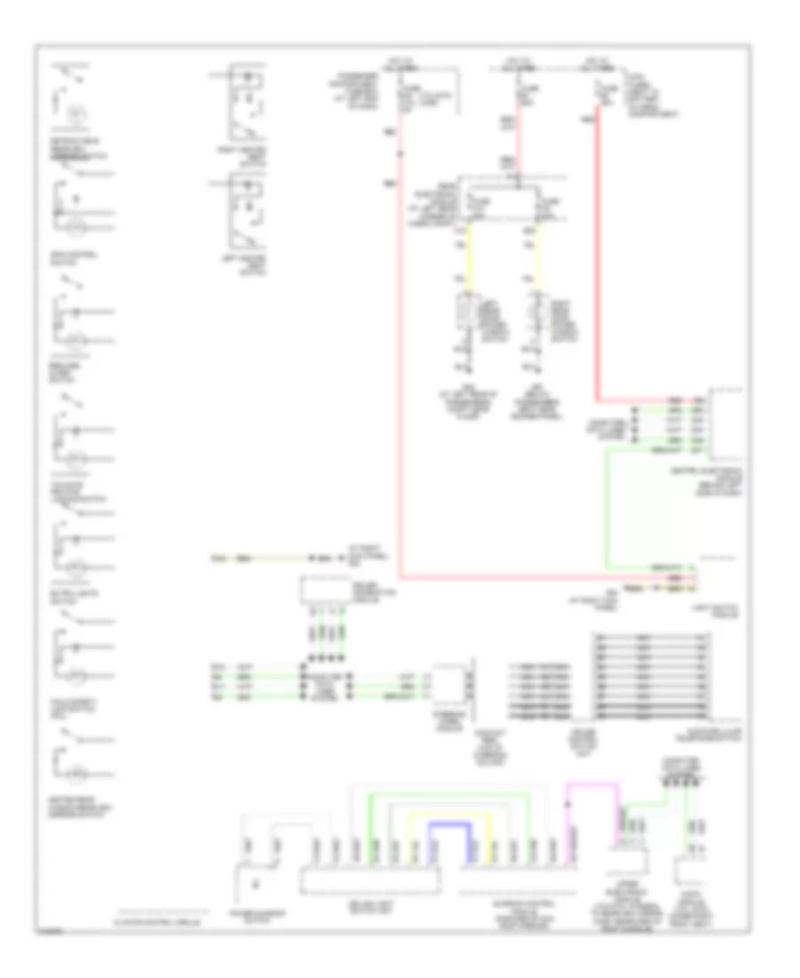
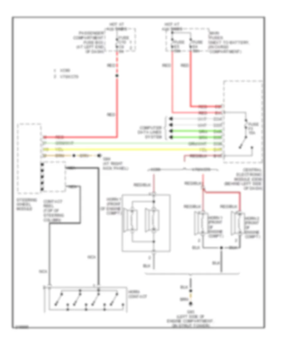
Звуковой сигнал Гудок
Электросхема звукового сигнал Гудка для Volvo V70 T-5 2005
 https://portal-diagnostov.com/license.html
Automotive Electricians Portal FZCO
Automotive Electricians Portal FZCO
https://portal-diagnostov.com/license.html
https://portal-diagnostov.com/license.html
Automotive Electricians Portal FZCO
Automotive Electricians Portal FZCOЭлектросхема звукового сигнал Гудка для Volvo V70 T-5 2005 - Список элементов:
- B15
- Central electronic module (cem) (behind left side of dash)
- Computer data lines system
- Contact reel (top of steering column)
- D17
- D34
- D35
- D49
- D50
- D58
- Fuse c10 c9 5a
- Fuse e4 50a
- Fuse e5 50a
- Fuse f3 15a
- G84 (at right kick panel)
- G93 (left side of engine compartment, on strut tower)
- Horn 1 (front of engine compt)
- Horn 2 (front of engine compt)
- Horn contact
- Hot at all times
- Main fuses (next to battery, in cargo compartment)
- Nca
- Passenger compartment fuse box (at left end of dash)
- Red
- Steering wheel module
- V70/xc70
- Xc90
Магнитола Мультимедия
Электросхема магнитолы, С усилитель для Volvo V70 T-5 2005
 https://portal-diagnostov.com/license.html
Automotive Electricians Portal FZCO
Automotive Electricians Portal FZCO
https://portal-diagnostov.com/license.html
https://portal-diagnostov.com/license.html
Automotive Electricians Portal FZCO
Automotive Electricians Portal FZCOЭлектросхема магнитолы, С усилитель для Volvo V70 T-5 2005 - Список элементов:
- (at right
- (under front passenger's seat) (if equipped) cd-changer
- (under right
- A10
- A11
- A12
- Amplifier (under front passenger's seat)
- Audio module
- Audio telephone switch
- B10
- B11
- B12
- B17
- B18
- Bass speaker (if equipped)
- Brake control module (at left rear corner of engine compt)
- Bumper antenna
- Bumper antenna amplifier
- Center dashboard speaker
- Central electronic module (behind left side of dash)
- Computer data lines system
- Contact reel
- Cruise control switch (sws)
- D32
- D35
- D37
- D47
- D50
- D52
- D58
- Din (or coaxial cable)
- Front seat)
- Fuse 15a
- Fuse 50a
- Fuse 5a
- Fuse 60a
- Fuse 7.5a
- Fuse c10 20a
- Fuse c11 30a
- G72 (left rear of cargo compt)
- G73 (at right rear of passenger's compt, near floor)
- G84
- Hot at all times
- Kick panel)
- Left d-pillar speaker
- Left front door speaker
- Left front door treble speaker
- Left rear door speaker
- Left rear window antenna
- Left window antenna amplifier 1
- Main fuses (next to battery, in cargo compt)
- Nca
- Passenger compartment fuse box (at left end of dash)
- Rear electronic module (at left rear corner of cargo compt)
- Red
- Right d-pillar speaker
- Right front door speaker
- Right front door treble speaker
- Right rear door speaker
- Rti module (left rear corner of cargo compt)
- Solid state
- Steering wheel module (swm)
Электросхема магнитолы, без Усилитель для Volvo V70 T-5 2005
 https://portal-diagnostov.com/license.html
Automotive Electricians Portal FZCO
Automotive Electricians Portal FZCO
https://portal-diagnostov.com/license.html
https://portal-diagnostov.com/license.html
Automotive Electricians Portal FZCO
Automotive Electricians Portal FZCOЭлектросхема магнитолы, без Усилитель для Volvo V70 T-5 2005 - Список элементов:
- (under right front seat) audio module
- A10
- A11
- A12
- Audio/cellular telephone switch
- B10
- B11
- B12
- Brake control module (at left rear of engine compt)
- Central electronic module (behind left side of dash)
- Computer data lines system
- Contact reel
- Cruise control switch unit (sws)
- D32
- D37
- D47
- D52
- Din (or coaxial cable)
- Fuse 50a
- Fuse 5a
- Fuse c10 20a
- G84 (right kick panel)
- Hot at all times
- Left d-pillar speaker
- Left front door speaker
- Left front door treble speaker
- Left rear door speaker
- Left rear window antenna
- Left window antenna amplifier 1
- Main fuses (next to battery, in cargo compt)
- Nca
- Passenger compartment fuse box (at left end of dash)
- Red
- Right d-pillar speaker
- Right front door speaker
- Right front door treble speaker
- Right rear door speaker
- Solid state
- Steering wheel module (swm)
Навигация GPS Парктроники
Электросхема парктроников для Volvo V70 T-5 2005
 https://portal-diagnostov.com/license.html
Automotive Electricians Portal FZCO
Automotive Electricians Portal FZCO
https://portal-diagnostov.com/license.html
https://portal-diagnostov.com/license.html
Automotive Electricians Portal FZCO
Automotive Electricians Portal FZCOЭлектросхема парктроников для Volvo V70 T-5 2005 - Список элементов:
- (at left rear corner of cargo compt) rear electronic module
- (on front bumper)
- (on rear bumper)
- (v70/xc70: at left rear
- (xc90: at right rear
- A10
- A11
- A12
- B21
- C10
- C11
- C12
- C13
- C14
- Computer
- D32
- Data lines
- Front parking assistance sensor 5
- Front parking assistance sensor 6
- Front parking assistance sensor 7
- Front parking assistance sensor 8
- Fuse e1 60a
- G72
- Hot at all times
- In cargo compt)
- Main fuses (next to battery,
- Of cargo compt)
- Parking assistance module (at left rear corner of cargo compt)
- Rear parking assistance sensor 1
- Rear parking assistance sensor 2
- Rear parking assistance sensor 3
- Rear parking assistance sensor 4
- System
схема информации о дорожном движении для Volvo V70 T-5 2005
 https://portal-diagnostov.com/license.html
Automotive Electricians Portal FZCO
Automotive Electricians Portal FZCO
https://portal-diagnostov.com/license.html
https://portal-diagnostov.com/license.html
Automotive Electricians Portal FZCO
Automotive Electricians Portal FZCOсхема информации о дорожном движении для Volvo V70 T-5 2005 - Список элементов:
- (above right rear window) right window antenna amplifier 1
- (above right rear window) right window antenna amplifier 2
- (at right side of rear bumper) bumper antenna
- (at top left side of dash) rti gps antenna
- (behind left side of dash) central electronic module
- A13
- A15
- Audio module (under right front seat)
- Audio/cellular phone switch
- B10
- Bumper antenna amplifier (at right rear corner of cargo compt)
- C10
- C13
- C14
- Central electronic module (behind left side of dash)
- Computer data lines system
- Contact reel (top of steering column)
- Cruise control switch
- D35
- D37
- D50
- D52
- D58
- Fuse c12 10a
- Fuse e1 60a
- Fuse e4 50a
- Fuse f28 5a
- Fuse f6 7.5a
- G72 (at left rear of cargo compt)
- G84 (at right kick panel)
- Hot at all times
- Hot in on or start
- Left front door speaker
- Left rear window antenna
- Left tv
- Left window antenna amplifier 2 (above left rear window)
- Main fuses (next to battery, in cargo compt)
- Nca
- Nca nca
- Passenger compartment fuse box (at left end of dash)
- Pnk
- Rear electronic module (at left rear corner of cargo compt)
- Red
- Right rear window antenna
- Road traffic information (left rear corner of cargo compt)
- Rti
- Rti display
- Rti switch
- Steering wheel module (in steering column)
- Tv receiver (left rear corner of cargo compt)
- Window antenna amplifier 1 (above left rear window)
Подогрев стекол и зеркал
Электросхема подогрева зеркал заднего вида для Volvo V70 T-5 2005
 https://portal-diagnostov.com/license.html
Automotive Electricians Portal FZCO
Automotive Electricians Portal FZCO
https://portal-diagnostov.com/license.html
https://portal-diagnostov.com/license.html
Automotive Electricians Portal FZCO
Automotive Electricians Portal FZCOЭлектросхема подогрева зеркал заднего вида для Volvo V70 T-5 2005 - Список элементов:
- (v70/xc70) (xc90)
- A10
- A11
- B10
- B11
- B12
- Climate control module
- Computer data lines system
- Driver door control module (ddm)
- Fuse c4 c6 25a
- Fuse c5 25a
- G66 (below driver's seat, near rocker panel)
- G67 (below passenger's seat, near rocker panel)
- Heated rear window/rearview mirrors switch
- Hot at all times
- Interior lights system
- Left power door mirror (in left rearview mirror)
- Mirror heating element
- Nca
- Passenger compartment fuse box (at left end of dash)
- Passenger door control module (pdm)
- Red
- Right power door mirror (in right rearview mirror)
- Xc90
Электросхема заднего стекла для Volvo V70 T-5 2005
 https://portal-diagnostov.com/license.html
Automotive Electricians Portal FZCO
Automotive Electricians Portal FZCO
https://portal-diagnostov.com/license.html
https://portal-diagnostov.com/license.html
Automotive Electricians Portal FZCO
Automotive Electricians Portal FZCOЭлектросхема заднего стекла для Volvo V70 T-5 2005 - Список элементов:
- A10
- A11
- C13
- C14
- Climate
- Computer data lines system
- Control
- Fuse 20a
- Fuse e1 60a
- G72 (v70: at left rear of cargo compt) (xc90: at right rear of cargo compt)
- Heated rear window
- Heated rear window/ rearview mirrors switch
- Hot at all times
- Main fuses (next to battery in cargo compt)
- Module
- Rear electronic module (at left rear corner of cargo compt)
- Red
ПОДУШКИ БЕЗОПАСНОСТИ AIR BAG
Электросхема подушек безопасности SRS AirBag (1 из 2) для Volvo V70 T-5 2005
 https://portal-diagnostov.com/license.html
Automotive Electricians Portal FZCO
Automotive Electricians Portal FZCO
https://portal-diagnostov.com/license.html
https://portal-diagnostov.com/license.html
Automotive Electricians Portal FZCO
Automotive Electricians Portal FZCOЭлектросхема подушек безопасности SRS AirBag (1 из 2) для Volvo V70 T-5 2005 - Список элементов:
- (at left "c" pillar) rear left belt tensioner igniter
- (near rear of left front door) left front side impact sensor
- 31/46 (at left rear of passenger's compartment, near floor)
- 31/67 (below passenger seat, near rocker panel)
- A10
- Acc
- Central electronic module (behind left side of dash)
- Contact reel (top of steering column)
- D20
- D33
- D34
- D37
- D40
- D48
- D49
- D52
- D55
- Data link connector (partial) (below left side of dash)
- Driver information module (dim) (in instrument cluster)
- Driver side air bag igniter (in steering wheel)
- Driver side air bag igniter step 2 (in steering wheel)
- Front left belt tensioner igniter (at left "b" pillar)
- Front left side air bag igniter (on left front seat back)
- Fuse f10 10a
- Hot at all times
- Ignition switch
- Left rear side impact sensor (near rear of left rear door)
- Nca
- Occupant weight sensor (under front passenger's seat)
- Off
- Passenger side air bag igniter (behind right side of dash)
- Passenger side air bag stage 2 igniter (behind right side of dash)
- Solid state
- Start
Электросхема подушек безопасности SRS AirBag (2 из 2) для Volvo V70 T-5 2005
 https://portal-diagnostov.com/license.html
Automotive Electricians Portal FZCO
Automotive Electricians Portal FZCO
https://portal-diagnostov.com/license.html
https://portal-diagnostov.com/license.html
Automotive Electricians Portal FZCO
Automotive Electricians Portal FZCOЭлектросхема подушек безопасности SRS AirBag (2 из 2) для Volvo V70 T-5 2005 - Список элементов:
- (behind left side of front bumper) left front impact sensor
- (behind right side of front bumper) right front impact sensor
- (near rear of right front door) right front side impact sensor
- 31/47 (left rear of passenger's compartment, near floor)
- 31/67 (below passenger's seat, near rocker panel)
- Center rear belt tensioner igniter (in center rear belt tensioner assembly)
- Computer data lines system
- Front right seat belt tensioner igniter (at right "b" pillar)
- Front right side air bag igniter (on right front seat back)
- Left hand seat belt buckle switch
- Left inflatable curtain igniter (in roof, above left rear window)
- Nca
- Rear hand seat belt buckle switch
- Rear right belt tensioner igniter (at right "c" pillar)
- Right inflatable curtain igniter (in roof, above right rear window)
- Right rear side impact sensor (near rear of right rear door)
- Solid state
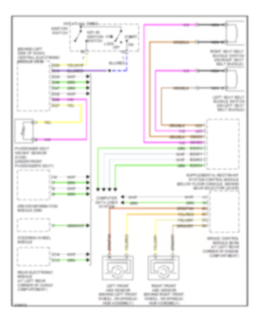
ПРЕДУПРЕЖДАЮЩИЕ СИСТЕМЫ
Электросхема предупреждающей системы для Volvo V70 T-5 2005
 https://portal-diagnostov.com/license.html
Automotive Electricians Portal FZCO
Automotive Electricians Portal FZCO
https://portal-diagnostov.com/license.html
https://portal-diagnostov.com/license.html
Automotive Electricians Portal FZCO
Automotive Electricians Portal FZCOЭлектросхема предупреждающей системы для Volvo V70 T-5 2005 - Список элементов:
- (behind left side of dash) central electronic module (cem)
- A25
- A26
- Acc
- B23/51
- B24/52
- B25/53
- B26/54
- Brake control module (bcm) (at left rear corner of engine compartment)
- C13
- C14
- C81/25
- C82/26
- Computer data lines system
- D16
- D27
- D28
- D32
- D34
- D47
- D49
- D60
- Driver information module (dim)
- Hot at all times
- Ignition switch
- Key-in ignition switch
- Left front abs sensor (behind left front wheel, on spindle/ hub assembly)
- Left seat belt buckle switch (on left seat belt buckle)
- Lock off
- Nca
- Passenger seat weight sensor (xc90) (under front passenger's seat)
- Rear electronic module (at left rear corner of cargo compartment)
- Right front abs sensor (behind right front wheel, on spindle/ hub assembly)
- Right seat belt buckle switch (on right seat belt buckle)
- Start
- Steering wheel module
ПРИБОРНАЯ ПАНЕЛЬ
Электросхема панели приборов для Volvo V70 T-5 2005
 https://portal-diagnostov.com/license.html
Automotive Electricians Portal FZCO
Automotive Electricians Portal FZCO
https://portal-diagnostov.com/license.html
https://portal-diagnostov.com/license.html
Automotive Electricians Portal FZCO
Automotive Electricians Portal FZCOЭлектросхема панели приборов для Volvo V70 T-5 2005 - Список элементов:
- (at left rear corner of engine compt) brake control module (bcm)
- (behind left front wheel, on spindle/ hub assembly) left front abs sensor
- (behind left side of dash) central electronic module
- (behind right front wheel, on spindle/ hub assembly) right front abs sensor
- (in windshield washer reservoir) washer fluid level sensor
- 2.4l
- 2.5l turbo & 2.4l turbo
- A/t
- A10
- A14
- A18
- A26
- A39
- A40
- A48
- A58
- A60
- A61
- A66
- A68
- B13
- B14
- B46
- Brake fluid level sensor (on brake fluid reservoir)
- C10
- C13
- C14
- C21
- C22
- Computer data lines system
- Coolant level sensor (on engine coolant reservoir)
- Coolant temperature sensor (left front of engine)
- D32
- D34
- D43
- D44
- D45
- D47
- D49
- Driver information module
- Ejector side fuel level sensor
- Engine control module (ecm) (at right side of engine compt, forward of strut tower)
- Except 2.4l 2.4l
- Except v70r
- Fuel pump (in fuel tank)
- Fuse e4 50a
- Fuse e5 50a
- Fuse f10 10a
- G1 (right side of engine compt, on strut tower)
- G83 (at left kick panel)
- G93 (left side of engine compt, on strut tower)
- Hot at all times
- Impulse sensor
- M/t
- Main fuses (next to battery, in cargo compt)
- Nca
- Oil level sensor (lower left front of engine)
- Oil pressure monitor (on left side of engine)
- Outside temperature sensor
- Parking brake switch (v70/xc70: at base of parking brake lever) (xc90: at top of parking brake pedal assembly)
- Passenger door module (pdm)
- Passenger door power mirror
- Pump side fuel level sensor
- Rear electronic module (rem) (at left rear corner of cargo compt)
- Red
- Transmission control module (tcm) (at right side of engine compt, forward of strut tower)
- V70r
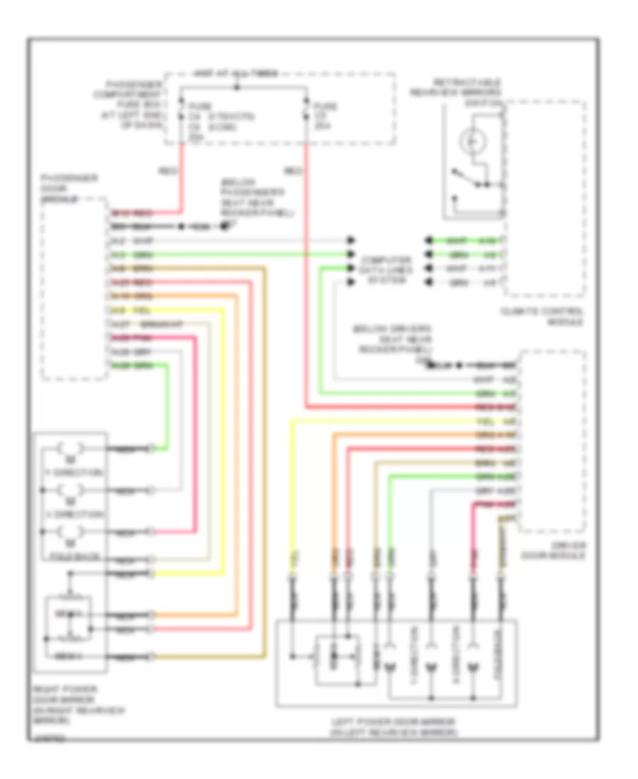
ПРИВОД ЗЕРКАЛ
Электросхема привода зеркал для Volvo V70 T-5 2005
 https://portal-diagnostov.com/license.html
Automotive Electricians Portal FZCO
Automotive Electricians Portal FZCO
https://portal-diagnostov.com/license.html
https://portal-diagnostov.com/license.html
Automotive Electricians Portal FZCO
Automotive Electricians Portal FZCOЭлектросхема привода зеркал для Volvo V70 T-5 2005 - Список элементов:
- (below driver's seat near rocker panel) g66
- (below passenger's seat near rocker panel) g67
- (v70/xc70) (xc90)
- A10
- A11
- A25
- A26
- A27
- A28
- A29
- B12
- Climate control module
- Computer data lines system
- Driver door module
- Fold back
- Fold-back
- Fuse c4 c6 25a
- Fuse c5 25a
- Hot at all times
- Left power door mirror (in left rearview mirror)
- Mem x
- Mem y
- Nca
- Passenger compartment fuse box (at left end of dash)
- Passenger door module
- Pnk
- Red
- Retractable rearview mirrors switch
- Right power door mirror (in right rearview mirror)
- X direction
- X-direction
- Y direction
- Y-direction
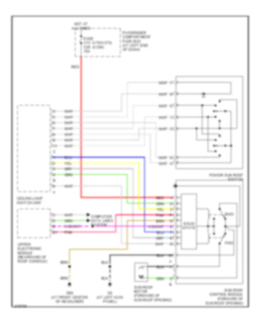
ПРИВОД ЛЮКА И КРЫШИ
Электросхема привода люка или крыши для Volvo V70 T-5 2005
 https://portal-diagnostov.com/license.html
Automotive Electricians Portal FZCO
Automotive Electricians Portal FZCO
https://portal-diagnostov.com/license.html
https://portal-diagnostov.com/license.html
Automotive Electricians Portal FZCO
Automotive Electricians Portal FZCOЭлектросхема привода люка или крыши для Volvo V70 T-5 2005 - Список элементов:
- (v70/xc70) (xc90)
- Bwd
- Ceiling light switch unit
- Computer data lines system
- Fuse c13 c26 15a
- Fwd
- G6 (at left kick panel)
- G98 (at front center of headliner)
- Hot at all times
- Passenger compartment fuse box (at left end of dash)
- Pnk
- Power sun roof switch
- Red
- Solid state
- Sun roof control module (forward of sun roof opening)
- Sun roof motor (forward of sun roof opening)
- Upper electronic module (rearward of roof console)
ПРИВОД СТЕКЛОПОДЪЕМНИКОВ
Электросхема стеклоподъемников для Volvo V70 T-5 2005
 https://portal-diagnostov.com/license.html
Automotive Electricians Portal FZCO
Automotive Electricians Portal FZCO
https://portal-diagnostov.com/license.html
https://portal-diagnostov.com/license.html
Automotive Electricians Portal FZCO
Automotive Electricians Portal FZCOЭлектросхема стеклоподъемников для Volvo V70 T-5 2005 - Список элементов:
- (at left rear of passenger's compt, near floor) g46
- (below driver's seat, near rocker panel)
- (below passenger's seat, near rocker panel) g67
- (in left front door) left front power window motor
- (in right front door) right front power window motor
- A16
- A19
- A23
- A24
- B12
- B30
- C13
- C14
- C6 25a
- Computer data lines system
- Driver door module (ddm)
- Fuse 20a
- Fuse c4
- Fuse c5 25a
- Fuse e1 60a
- G66
- G67 (below passenger's seat, near rocker panel)
- Hot at all times
- Left rear door power window switch
- Left rear power window motor (in left rear door)
- Main fuses (next to battery, in cargo compt)
- Passenger compartment fuse box (at left end of dash)
- Passenger door module (pdm)
- Rear electronic module (at left rear corner of cargo compt)
- Red
- Red red
- Right rear door power window switch
- Right rear power window motor (in right rear door)
- Solid state
- V70/xc70
- Xc90
Противоугонная система Сигнализация
Электросхема открывания авто для Volvo V70 T-5 2005
 https://portal-diagnostov.com/license.html
Automotive Electricians Portal FZCO
Automotive Electricians Portal FZCO
https://portal-diagnostov.com/license.html
https://portal-diagnostov.com/license.html
Automotive Electricians Portal FZCO
Automotive Electricians Portal FZCOЭлектросхема открывания авто для Volvo V70 T-5 2005 - Список элементов:
- (above left rear window) g99
- (at left rear of cargo compt) g72
- (right side of engine compt, on strut tower) g94
- A10
- A11
- A12
- A13
- Alarm siren
- B25
- C12
- C13
- C14
- Central electronic module (behind left side of dash)
- Climate control module
- Computer data lines system
- D26
- D29
- D31
- D33
- D34
- D35
- D42
- D49
- D50
- Driver door module (ddm)
- Front mass movement sensor (center of roof)
- Fuse c6 10a
- Fuse e1 60a
- Fuse e4 50a
- Fuse e5 50a
- Fuse f8 5a
- G46 (at left rear of passenger's compt, near floor)
- G67 (below passenger's seat, near rocker panel)
- G72
- G93 (left side of engine compt, on strut tower)
- G98 (at front center of headliner)
- Hood alarm contact (at left front of engine compt)
- Hot at all times
- Inclination sensor module (left rear corner of cargo compt)
- Key
- Left front door lock unit (rear left front door)
- Left rear door lock unit (rear of left rear door)
- Left-hand glass breakage sensor (in left rear window)
- Lock
- Lock right front door lock unit (rear of right front door)
- Main fuses (next to battery, in cargo compt)
- Passenger compartment fuse box (at left end of dash)
- Passenger door module (pdm)
- Pnk
- Rear electronic module (at left rear corner of cargo compt)
- Red
- Reduced alarm switch
- Right rear door lock unit (rear right rear door)
- Right rear door power window switch
- Right-hand glass breakage sensor (in right rear window)
- Solar sensor, twilight sensor and indicator alarm (on top center of dash)
- Sunroof control module (forward of sun roof opening)
- Tailgate glass breakage sensor (in tailgate window)
- Tailgate lock unit (bottom rear of tailgate)
- Unlock
- Upper electronic module (integral to rearview mirror)
Электросхема иммобилайзера для Volvo V70 T-5 2005
 https://portal-diagnostov.com/license.html
Automotive Electricians Portal FZCO
Automotive Electricians Portal FZCO
https://portal-diagnostov.com/license.html
https://portal-diagnostov.com/license.html
Automotive Electricians Portal FZCO
Automotive Electricians Portal FZCOЭлектросхема иммобилайзера для Volvo V70 T-5 2005 - Список элементов:
- Acc
- Antenna ring/ ignition lighting
- B13
- C21
- C22
- Central electronic module (behind left side of dash)
- Computer data lines system
- D34
- D49
- D56
- D57
- Driver information module (dim)
- Engine control module (ecm) (at right side of engine compt, forward of strut tower)
- G83 (at left kick panel)
- Hot at all times
- Ignition switch
- Interior lights system
- Lock
- Off
- Start
СИСТЕМА АНТИБЛОКИРОВОЧНОЙ ТОРМОЗНОЙ СИСТЕМЫ ABS
Электросхема антиблокировочной тормозной системы АБС (ABS), С Динамическое Управление Стабильностью для Volvo V70 T-5 2005
 https://portal-diagnostov.com/license.html
Automotive Electricians Portal FZCO
Automotive Electricians Portal FZCO
https://portal-diagnostov.com/license.html
https://portal-diagnostov.com/license.html
Automotive Electricians Portal FZCO
Automotive Electricians Portal FZCOЭлектросхема антиблокировочной тормозной системы АБС (ABS), С Динамическое Управление Стабильностью для Volvo V70 T-5 2005 - Список элементов:
- (at front of engine compt) vacuum pump switch
- (left side of engine compt,
- (on brake master cylinder) dstc activation unit
- A10
- A11
- A37
- A55
- Abs pump motor
- B11
- B13
- B22
- B26
- Body cluster sensor (under front passenger's seat)
- Brake control module (at left rear corner of engine compt)
- Brake light contact (at top of brake pedal)
- Brake pedal sensor (at left rear corner of engine compt)
- Brake pressure sensor 1 (on brake master cylinder)
- Brake pressure sensor 2 (on brake master cylinder)
- C21
- C22
- C34
- C35
- Central electronic module (behind left side of dash)
- Climate control module
- Computer data lines system
- Contact reel
- D31
- D32
- D34
- D46
- D47
- D49
- Engine compartment distribution box (at left side of engine compt)
- Engine control module (at right side of engine compt, forward of strut tower)
- Fuse 20a
- Fuse 4 50a
- Fuse 50a
- Fuse 5a
- Fuse b14 30a
- Fuse b19 30a
- Fuse c9 c10 5a
- G84 (at right kick panel)
- G93 (left side of engine compt,on strut tower)
- G95
- Hot at all times
- Left front abs sensor (behind left front wheel, on spindle/ hub assembly)
- Left rear abs sensor (behind left rear wheel, on spindle/ hub assembly)
- Main fuses (next to battery, in cargo compt)
- Nca
- On strut tower)
- Passenger compartment fuse box (at left end of dash)
- Red
- Right front abs sensor (behind right front wheel, on spindle/ hub assembly)
- Right rear abs sensor (behind right rear wheel, on spindle/ hub assembly)
- Spin control switch
- Steering angle sensor module
- Steering wheel module (swm) (at top of steering column)
- V70/xc70
- Vacuum pump (at left rear of engine)
- Xc90
Электросхема антиблокировочной тормозной системы АБС (ABS), без Динамическое Управление Стабильностью для Volvo V70 T-5 2005
 https://portal-diagnostov.com/license.html
Automotive Electricians Portal FZCO
Automotive Electricians Portal FZCO
https://portal-diagnostov.com/license.html
https://portal-diagnostov.com/license.html
Automotive Electricians Portal FZCO
Automotive Electricians Portal FZCOЭлектросхема антиблокировочной тормозной системы АБС (ABS), без Динамическое Управление Стабильностью для Volvo V70 T-5 2005 - Список элементов:
- (at front of engine compt) vacuum pump switch
- A10
- A11
- A37
- A55
- Abs pump motor
- B11
- B13
- B22
- B26
- Brake control module (at left rear corner of engine compt)
- Brake light contact (at top of brake pedal)
- Brake pedal sensor (at left rear corner of engine compt)
- C21
- C22
- C34
- C35
- Central electronic module (behind left side of dash)
- Climate control module
- Computer data lines system
- Contact reel
- D32
- D34
- D47
- D49
- Engine compartment distribution box (at left side of engine compt)
- Engine control module (at right side of engine compt, forward of strut tower)
- Fuse 20a
- Fuse 4 50a
- Fuse 50a
- Fuse 5a
- Fuse b14 30a
- Fuse b19 30a
- Fuse c9 c10 5a
- G84 (at right kick panel)
- G93 (left side of engine compt, on strut tower)
- G95 (left side of engine compt,
- Hot at all times
- Left front abs sensor (behind left front wheel, on spindle/ hub assembly)
- Left rear abs sensor (behind left rear wheel, on spindle/ hub assembly)
- Main fuses (next to battery, in cargo compt)
- Nca
- On strut tower)
- Passenger compartment fuse box (at left end of dash)
- Red
- Right front abs sensor (behind right front wheel, on spindle/ hub assembly)
- Right rear abs sensor (behind right rear wheel, on spindle/ hub assembly)
- Spin control switch
- Steering wheel module (swm) (at top of steering column)
- V70/xc70
- Vacuum pump (at left rear of engine)
- Xc90
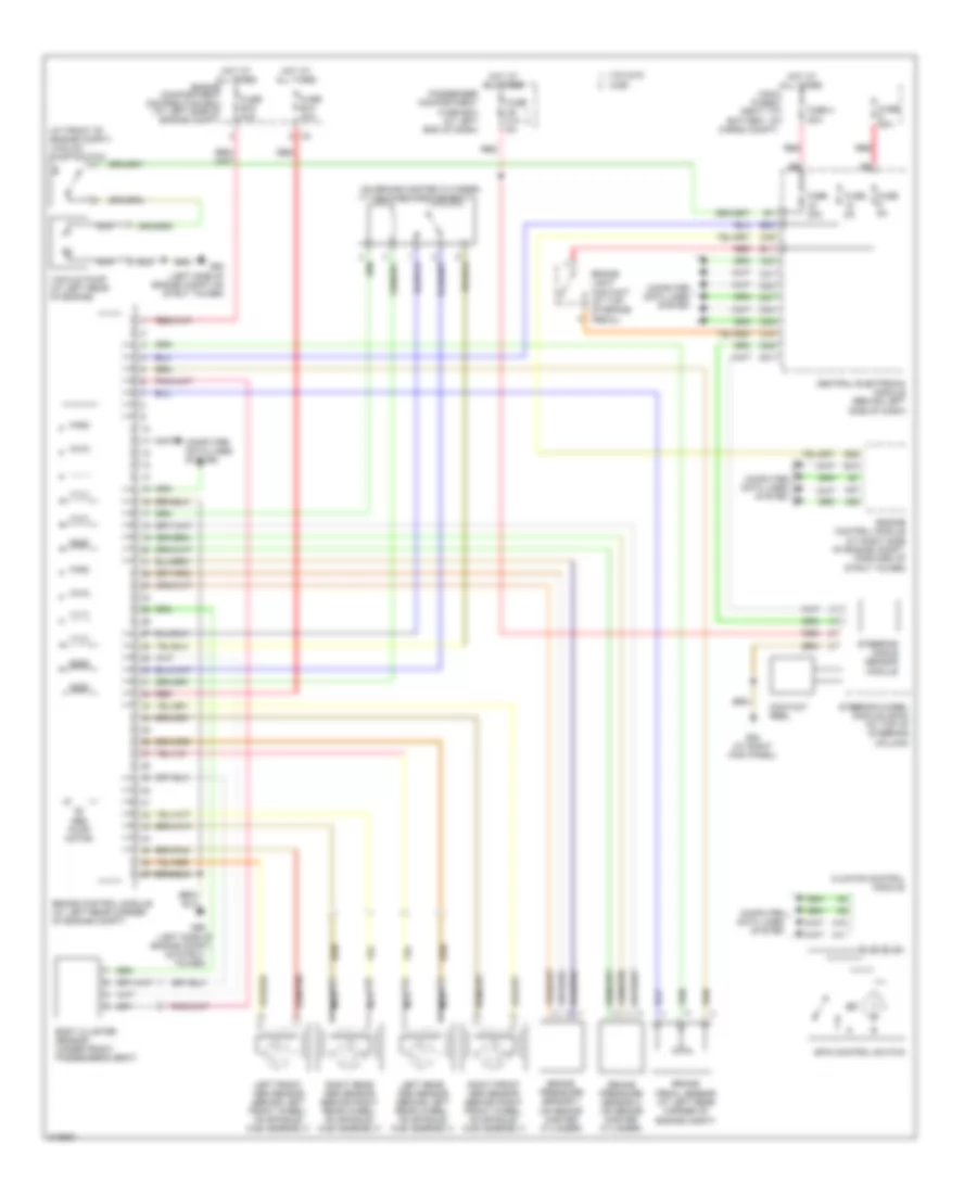
СИСТЕМА КОНДИЦИОНЕРА
2.4L
2.4L, Электросхема кондиционера с ручный управлением (1 из 2) для Volvo V70 T-5 2005
 https://portal-diagnostov.com/license.html
Automotive Electricians Portal FZCO
Automotive Electricians Portal FZCO
https://portal-diagnostov.com/license.html
https://portal-diagnostov.com/license.html
Automotive Electricians Portal FZCO
Automotive Electricians Portal FZCO2.4L, Электросхема кондиционера с ручный управлением (1 из 2) для Volvo V70 T-5 2005 - Список элементов:
- (not used)
- A10
- A11
- A12
- A13
- A14
- A15
- A16
- Battery fuse box (next to battery)
- C21
- C22
- Central electronic module (cem) (behind left side of dash)
- Climate control module
- Climate control system relay
- Computer data lines system
- D29
- D32
- D42
- D47
- Electromagnetic clutch (left front of engine)
- Engine compartment fuse box (at left side of engine compt, forward of strut tower)
- Engine management system main relay
- Evaporator temperature sensor (near center of hvac housing)
- Fuse a8 60a
- Fuse b11 20a
- Fuse b23 10a
- Fuse b8 10a
- Fuse e4 50a
- Fuse e5 50a
- G84 (at right kick panel)
- Hot at all times
- Left-hand side temperature damper motor module (on left end of hvac housing)
- Recirculation damper motor module (on lower right side of hvac housing)
- Red
- Right-hand side temperature damper motor module (near center of hvac housing)
- Solar sensor, dusk sensor & indicator alarm (on top center of dash)
- Solid state
- Ventilation/floor/defroster damper motor module (near center of hvac housing)
2.4L, Электросхема кондиционера с ручный управлением (2 из 2) для Volvo V70 T-5 2005
 https://portal-diagnostov.com/license.html
Automotive Electricians Portal FZCO
Automotive Electricians Portal FZCO
https://portal-diagnostov.com/license.html
https://portal-diagnostov.com/license.html
Automotive Electricians Portal FZCO
Automotive Electricians Portal FZCO2.4L, Электросхема кондиционера с ручный управлением (2 из 2) для Volvo V70 T-5 2005 - Список элементов:
- (at left side of engine compt, forward of strut tower) engine compartment fuse box
- A14
- A18
- A21
- A37
- A40
- A55
- A58
- A61
- Ambient temperature sensor
- B11
- B13
- B38
- B44
- Climate control system pressure sensor (at right front of engine compt)
- Computer data lines system
- Coolant temperature sensor (left front of engine)
- Cooling fan control module (at front center of engine compt)
- Cooling fan motor (front of engine compt)
- Engine control module (ecm) (at right side of engine compt, forward of strut tower)
- Fan control module (behind right side of dash, near blower fan)
- Fuse c3 30a
- G10 (at right kick panel)
- G2 (in engine compt, on left strut tower)
- Hot at all times
- Nca
- Passenger compartment fan motor (on lower right side of hvac housing)
- Passenger compartment fuse box (at left end of dash)
- Passenger/driver door module (pdm/ddm)
- Red
- Right power door mirror (in right rearview mirror)
- Solid state
2.4L ТУРБО
2.4L Турбо, Электросхема кондиционера (1 из 2) для Volvo V70 T-5 2005
 https://portal-diagnostov.com/license.html
Automotive Electricians Portal FZCO
Automotive Electricians Portal FZCO
https://portal-diagnostov.com/license.html
https://portal-diagnostov.com/license.html
Automotive Electricians Portal FZCO
Automotive Electricians Portal FZCO2.4L Турбо, Электросхема кондиционера (1 из 2) для Volvo V70 T-5 2005 - Список элементов:
- (not used)
- A10
- A11
- A12
- A13
- A14
- A15
- A16
- Air quality sensor (at right side of plenum)
- Battery fuse box (next to battery)
- C21
- C22
- Central electronic module (cem) (behind left side of dash)
- Climate control module
- Climate control system relay
- Computer data lines system
- D29
- D30
- D32
- D42
- D47
- Defroster damper motor module (near center of hvac housing)
- Electromagnetic clutch (left front of engine)
- Engine compartment fuse box (at left side of engine compt, forward of strut tower)
- Engine management system main relay
- Evaporator temperature sensor (near center of hvac housing)
- Floor/ventilation damper motor module (near center of hvac housing)
- Fuse a8 60a
- Fuse b11 20a
- Fuse b23 10a
- Fuse b8 10a
- Fuse e4 50a
- Fuse e5 50a
- G84 (at right kick panel)
- Hot at all times
- Left-hand side temperature damper motor module (on left end of hvac housing)
- Recirculation damper motor module (on lower right side of hvac housing)
- Red
- Right-hand side temperature damper motor module (near center of hvac housing)
- Solar sensor, dusk sensor & indicator alarm (on top center of dash)
- Solid state
2.4L Турбо, Электросхема кондиционера (2 из 2) для Volvo V70 T-5 2005
 https://portal-diagnostov.com/license.html
Automotive Electricians Portal FZCO
Automotive Electricians Portal FZCO
https://portal-diagnostov.com/license.html
https://portal-diagnostov.com/license.html
Automotive Electricians Portal FZCO
Automotive Electricians Portal FZCO2.4L Турбо, Электросхема кондиционера (2 из 2) для Volvo V70 T-5 2005 - Список элементов:
- (at left side of engine compt, forward of strut tower) engine compartment fuse box
- A14
- A18
- A39
- A60
- A68
- Ambient temperature sensor
- B11
- B13
- B38
- B44
- Climate control system pressure sensor (at right front of engine compt)
- Computer data lines system
- Coolant temperature sensor (left front of engine)
- Cooling fan control module (at front center of engine compt)
- Cooling fan motor (front of engine compt)
- Engine control module (ecm) (at right side of engine compt, forward of strut tower)
- Fan control module (behind right side of dash, near blower fan)
- Fuse c1 30a
- Fuse c3 30a
- G10 (at right kick panel)
- G2 (in engine compt, on left strut tower)
- Hot at all times
- Nca
- Passenger compartment fan motor (on lower right side of hvac housing)
- Passenger compartment fuse box (at left end of dash)
- Passenger/driver door module (pdm/ddm)
- Red
- Right power door mirror (in right rearview mirror)
- Solid state
- V70/xc70
- Xc90
2.5L ТУРБО
2.5L Турбо, Электросхема кондиционера (1 из 2) для Volvo V70 T-5 2005
 https://portal-diagnostov.com/license.html
Automotive Electricians Portal FZCO
Automotive Electricians Portal FZCO
https://portal-diagnostov.com/license.html
https://portal-diagnostov.com/license.html
Automotive Electricians Portal FZCO
Automotive Electricians Portal FZCO2.5L Турбо, Электросхема кондиционера (1 из 2) для Volvo V70 T-5 2005 - Список элементов:
- (not used)
- A10
- A11
- A12
- A13
- A14
- A15
- A16
- Air quality sensor (at right side of plenum)
- Battery fuse box (next to battery)
- C21
- C22
- Central electronic module (cem) (behind left side of dash)
- Climate control module
- Climate control system relay
- Computer data lines system
- D29
- D30
- D32
- D42
- D47
- Defroster damper motor module (near center of hvac housing)
- Electromagnetic clutch (left front of engine)
- Engine compartment fuse box (at left side of engine compt, forward of strut tower)
- Engine management system main relay
- Evaporator temperature sensor (near center of hvac housing)
- Floor/ventilation damper motor module (near center of hvac housing)
- Fuse a8 60a
- Fuse b11 20a
- Fuse b23 10a
- Fuse b8 10a
- Fuse e4 50a
- Fuse e5 50a
- G84 (at right kick panel)
- Hot at all times
- Left-hand side temperature damper motor module (on left end of hvac housing)
- Recirculation damper motor module (on lower right side of hvac housing)
- Red
- Right-hand side temperature damper motor module (near center of hvac housing)
- Solar sensor, dusk sensor & indicator alarm (on top center of dash)
- Solid state
2.5L Турбо, Электросхема кондиционера (2 из 2) для Volvo V70 T-5 2005
 https://portal-diagnostov.com/license.html
Automotive Electricians Portal FZCO
Automotive Electricians Portal FZCO
https://portal-diagnostov.com/license.html
https://portal-diagnostov.com/license.html
Automotive Electricians Portal FZCO
Automotive Electricians Portal FZCO2.5L Турбо, Электросхема кондиционера (2 из 2) для Volvo V70 T-5 2005 - Список элементов:
- (at left side of engine compt, forward of strut tower) engine compartment fuse box
- A14
- A18
- A39
- A60
- A68
- Ambient temperature sensor
- B11
- B13
- B38
- B44
- Climate control system pressure sensor (at right front of engine compt)
- Computer data lines system
- Coolant temperature sensor (left front of engine)
- Cooling fan control module (at front center of engine compt)
- Cooling fan motor (front of engine compt)
- Engine control module (ecm) (at right side of engine compt, forward of strut tower)
- Fan control module (behind right side of dash, near blower fan)
- Fuse c1 30a
- Fuse c3 30a
- G10 (at right kick panel)
- G2 (in engine compt, on left strut tower)
- Hot at all times
- Nca
- Passenger compartment fan motor (on lower right side of hvac housing)
- Passenger compartment fuse box (at left end of dash)
- Passenger/driver door module (pdm/ddm)
- Red
- Right power door mirror (in right rearview mirror)
- Solid state
- V70/xc70
- Xc90
СИСТЕМА КРУИЗКОНТРОЛЯ
Электросхема системы круизконтроля для Volvo V70 T-5 2005
 https://portal-diagnostov.com/license.html
Automotive Electricians Portal FZCO
Automotive Electricians Portal FZCO
https://portal-diagnostov.com/license.html
https://portal-diagnostov.com/license.html
Automotive Electricians Portal FZCO
Automotive Electricians Portal FZCOЭлектросхема системы круизконтроля для Volvo V70 T-5 2005 - Список элементов:
- (near accelerator pedal) accelerator sensor
- (top of steering column) contact reel
- 2.4l
- 2.4l turbo,
- 2.5l turbo, 2.9l turbo
- A19
- A20
- A25
- A35
- A36
- A43
- A59
- B11
- B13
- B15
- B17
- B25
- B38
- Brake control module (at left rear corner of engine compt)
- Brake pedal sensor (at left rear corner of engine compt)
- Central electronic module (behind left side of dash)
- Clutch pedal sensor (behind left side of dash)
- Computer data lines system
- Cruise control switch
- D58
- Engine
- Engine compt distribution box (left side of engine compt)
- Engine control module (at right side of engine compt, forward of strut tower)
- Engine throttle body (left side of engine)
- Fuse b23 10a
- Fuse b8 10a
- G93 (left side of engine compt, on strut tower)
- Hot at all times
- Instrument cluster
- Left front abs sensor (behind left front wheel, on spindle/hub assembly)
- Management system main relay
- Nca
- Red
- Right front abs sensor (behind right front wheel, on spindle/hub assembly)
- Steering wheel module
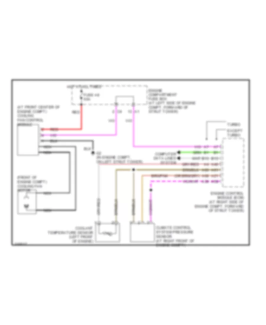
СИСТЕМА ОХЛАЖДЕНИЯ
Электросхема системы охлаждения для Volvo V70 T-5 2005
 https://portal-diagnostov.com/license.html
Automotive Electricians Portal FZCO
Automotive Electricians Portal FZCO
https://portal-diagnostov.com/license.html
https://portal-diagnostov.com/license.html
Automotive Electricians Portal FZCO
Automotive Electricians Portal FZCOЭлектросхема системы охлаждения для Volvo V70 T-5 2005 - Список элементов:
- (at front center of engine compt) cooling fan control module
- (front of engine compt) cooling fan motor
- A21
- A39
- A40
- A58
- A60
- A61
- A68
- B13
- Climate control system pressure sensor (at right front of engine compt)
- Computer data lines system
- Coolant temperature sensor (left front of engine)
- Engine compartment fuse box (at left side of engine compt, forward of strut tower)
- Engine control module (ecm) (at right side of engine compt, forward of strut tower)
- Except turbo
- Fuse a8 60a
- G2 (in engine compt, on left strut tower)
- Hot at all times
- Nca
- Red
- Turbo
СИСТЕМА ПЕРЕДАЧИ ДАННЫХ
Электросхема линии передачи данных CAN (1 из 2) для Volvo V70 T-5 2005
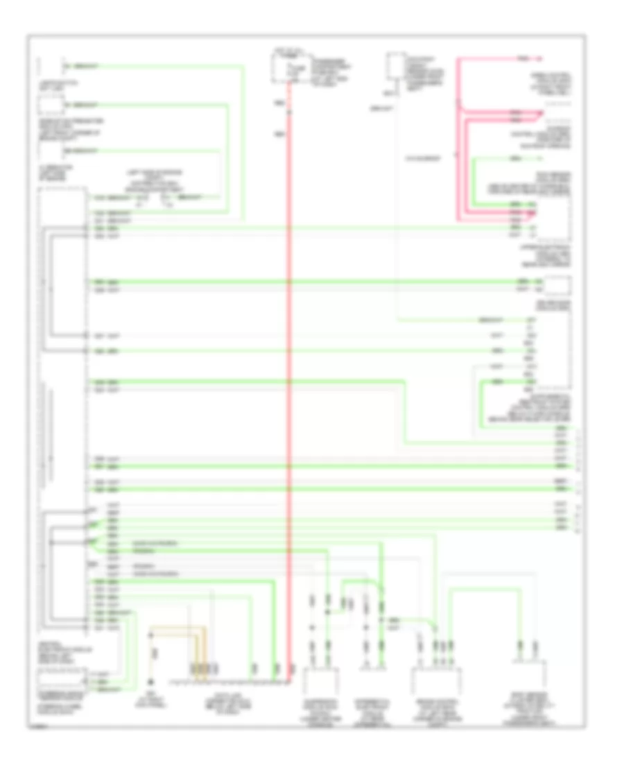 https://portal-diagnostov.com/license.html
Automotive Electricians Portal FZCO
Automotive Electricians Portal FZCO
https://portal-diagnostov.com/license.html
https://portal-diagnostov.com/license.html
Automotive Electricians Portal FZCO
Automotive Electricians Portal FZCOЭлектросхема линии передачи данных CAN (1 из 2) для Volvo V70 T-5 2005 - Список элементов:
- (awd w/o four-c)
- (four-c)
- (left side of engine compt) distribution box engine compartment
- A15
- A16
- Alternator (left side of engine)
- B23
- B24
- B25
- B26
- Body sensor cluster (bsc) (dynamic stability traction) (under front passenger's seat)
- Brake control module (bcm) (at left rear corner of engine compt)
- C16
- C21
- C22
- C32
- Central electronic module (behind left side of dash)
- Combustion preheater module (cpm) (left front corner of engine compt)
- D31
- D32
- D33
- D34
- D35
- D36
- D37
- D38
- D39
- D40
- D41
- D46
- D47
- D48
- D49
- D50
- D51
- D52
- D53
- D54
- D55
- D58
- Data link connector (dlc) (below left side of dash)
- Differential electronic module (at rear differential)
- Driver door module (ddm)
- Fuse c9 5a
- G84 (at right kick panel)
- Hot at all times
- Lights switch unit (lsm)
- Nca
- Occupant weight sensor (ows) (under front passenger's seat)
- Passenger compartment fuse box (at left end of dash)
- Pnk
- Rain sensor module (rsm) (above center of windshield, forward of rearview mirror)
- Red
- Siren control module (scm) (in right front wheelwell)
- Steering angle sensor module
- Steering wheel module (swm)
- Sunroof control module (srm) (forward of sun roof opening)
- Suspension module (sum) (four-c) (under center console)
- Upper electronic module (uem) (integral to rearview mirror)
- W/o sunroof
Электросхема линии передачи данных CAN (2 из 2) для Volvo V70 T-5 2005
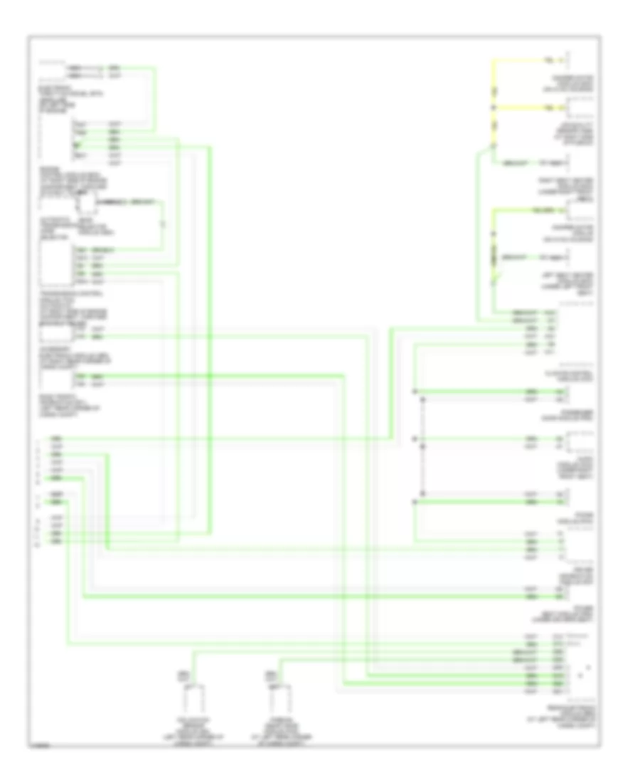 https://portal-diagnostov.com/license.html
Automotive Electricians Portal FZCO
Automotive Electricians Portal FZCO
https://portal-diagnostov.com/license.html
https://portal-diagnostov.com/license.html
Automotive Electricians Portal FZCO
Automotive Electricians Portal FZCOЭлектросхема линии передачи данных CAN (2 из 2) для Volvo V70 T-5 2005 - Список элементов:
- A10
- A11
- A12
- A37
- A55
- Accessory electronic module (aem) (at right rear corner of cargo compt)
- Air quality sensor (aqs) (at right side of plenum)
- Audio module (aum) (under right front seat)
- Automatic transmission mode selector
- B13
- B14
- B21
- C13
- C14
- Climate control module (ccm)
- D19
- D20
- D21
- D26
- D30
- D32
- Damper motor module (dmm) (on hvac housing)
- Damper motor module (on hvac housing)
- Driver information module (dim)
- Electronic throttle moduel (etm) (gasoline) (on left side of engine)
- Engine control module (ecm) (at right side of engine compartment, forward of strut tower)
- Gear selector module (gsm)
- Inclination sensor module (ism) (left rear corner of cargo compt)
- Left seat heater module (shm) (under left front seat)
- Nca
- Parking assistance module (pam) (at left rear corner of cargo compt)
- Passenger door module (pdm)
- Phone module (phm)
- Power seat module (psm) (under driver's seat)
- Rear electronic module (rem) (at left rear corner of cargo compt)
- Right seat heater module (shm) (under right front seat)
- Road traffic information (rti) (left rear corner of cargo compt)
- Transmission control module (tcm) (automatic) (at right side of engine compartment, forward of strut tower)
СИСТЕМА УПРАВЛЕНИЯ ДВИГАТЕЛЯ
2.4L
2.4L, Электросхема системы управления двигателем (1 из 3) для Volvo V70 T-5 2005
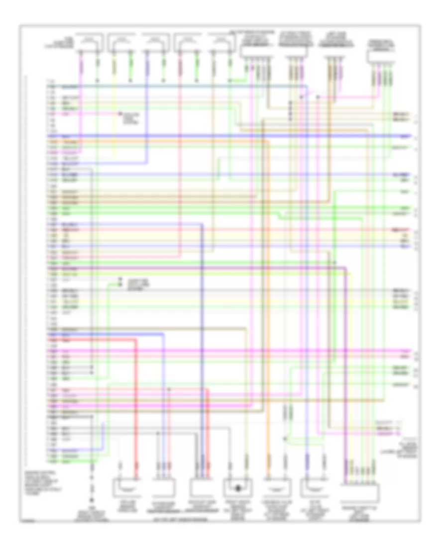 https://portal-diagnostov.com/license.html
Automotive Electricians Portal FZCO
Automotive Electricians Portal FZCO
https://portal-diagnostov.com/license.html
https://portal-diagnostov.com/license.html
Automotive Electricians Portal FZCO
Automotive Electricians Portal FZCO2.4L, Электросхема системы управления двигателем (1 из 3) для Volvo V70 T-5 2005 - Список элементов:
- (at right front of engine compt) climate control pressure sensor
- (left side of engine) intake manifold pressure sensor
- (on top left side of engine)
- (on top rear of engine,
- A10
- A11
- A12
- A13
- A14
- A15
- A16
- A17
- A18
- A19
- A20
- A21
- A22
- A23
- A24
- A25
- A26
- A27
- A28
- A29
- A30
- A31
- A32
- A33
- A34
- A35
- A36
- A37
- A38
- A39
- A40
- A41
- A42
- A43
- A44
- A45
- A46
- A47
- A48
- A49
- A50
- A51
- A52
- A53
- A54
- A55
- A56
- A57
- A58
- A59
- A60
- A61
- A62
- A63
- A64
- A65
- A66
- A67
- A68
- A69
- A70
- Computer data lines system
- Cooling fans system
- Engine control module (ecm) (at right side of engine compt, forward of strut tower)
- Engine throttle body (left side of engine)
- Evap valve (at left front of engine compt)
- Exhaust side camshaft position sensor
- Front knock sensor (on left front side of engine)
- Fuel injectors (top of engine)
- G96 (right side of engine compt, on strut tower)
- Impulse sensor (gasoline)
- In air duct) mass airflow (maf) sensor
- Intake side camshaft position sensor
- Oil level sensor (lower left front of engine)
- Pnk
- Pressure & temperature sensor
- Red
- Variable valve timing inlet solenoid (at top rear of engine)
2.4L, Электросхема системы управления двигателем (2 из 3) для Volvo V70 T-5 2005
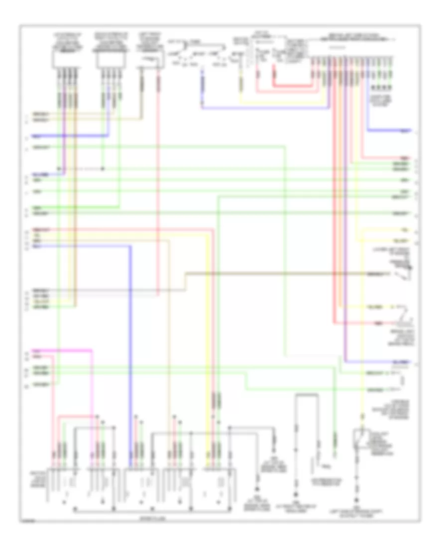 https://portal-diagnostov.com/license.html
Automotive Electricians Portal FZCO
Automotive Electricians Portal FZCO
https://portal-diagnostov.com/license.html
https://portal-diagnostov.com/license.html
Automotive Electricians Portal FZCO
Automotive Electricians Portal FZCO2.4L, Электросхема системы управления двигателем (2 из 3) для Volvo V70 T-5 2005 - Список элементов:
- (behind left side of dash) central electronic module (cem)
- (down stream of right catalytic converter) heated oxygen sensor diagnosis 1
- (left front of engine) coolant temperature sensor
- (lower left front of engine) oil pressure sensor
- (up stream of catalytic converter) heated oxygen sensor
- A16
- Acc
- Air preheating ptc resistor
- B11
- B16
- Battery fuse box (next to battery, in cargo compt)
- Brake light contact (at top of brake pedal)
- C14
- C21
- C22
- C34
- C35
- Computer data lines system
- Coolant level sensor (on engine coolant reservoir)
- D16
- D34
- D49
- D60
- Fuse e4 15a
- Fuse e5 10a
- G88 (at top of engine, near spark plugs)
- G89 (at top of engine, near spark plugs)
- G93 (left side of engine compt, on strut tower)
- G96 (at front center of headliner)
- Hot at all times
- Ignition coils (top of engine)
- Ignition switch
- Lock
- Nca
- Pnk
- Red
- Run
- Spark plugs
- Start
- Variable valve timing exhaust solenoid (on top front of engine)
2.4L, Электросхема системы управления двигателем (3 из 3) для Volvo V70 T-5 2005
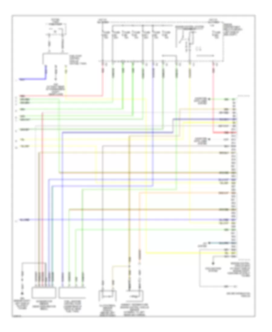 https://portal-diagnostov.com/license.html
Automotive Electricians Portal FZCO
Automotive Electricians Portal FZCO
https://portal-diagnostov.com/license.html
https://portal-diagnostov.com/license.html
Automotive Electricians Portal FZCO
Automotive Electricians Portal FZCO2.4L, Электросхема системы управления двигателем (3 из 3) для Volvo V70 T-5 2005 - Список элементов:
- (in fuel tank) fuel pump
- A/c system
- Accelerator sensor (near accelerator pedal)
- Ambient temperature engine control module sensor (integral to left rearview mirror)
- B10
- B11
- B12
- B13
- B14
- B15
- B16
- B17
- B18
- B19
- B20
- B21
- B22
- B23
- B24
- B25
- B26
- B27
- B28
- B29
- B30
- B31
- B32
- B33
- B34
- B35
- B36
- B37
- B38
- B39
- B40
- B41
- B42
- B43
- B44
- B45
- B46
- B47
- B48
- Clutch pedal sensor (manual) (behind left side of dash)
- Computer data lines system
- Cooling fans system
- Driver information module
- Engine compartment relay/fuse box (left side of eng compt)
- Engine control module (ecm) (at right side of engine compt, forward of strut tower)
- Engine control system main relay
- Fuel leakage control pump (under rear of vehicle, near fuel tank)
- Fuel pump control module (on fuel tank)
- Fuse b11 20a
- Fuse b21 15a
- Fuse b23 10a
- Fuse b3 10a
- Fuse b4 20a
- Fuse b5 10a
- Fuse b6 15a
- Fuse b8 10a
- G48 (at right rear of passenger's compt, near floor)
- G93 (engine compt, left side of on strut tower)
- Hot at all times
- Nca
- Red
2.4L ТУРБО
2.4L турбо, Электросхема системы управления двигателем (1 из 3) для Volvo V70 T-5 2005
 https://portal-diagnostov.com/license.html
Automotive Electricians Portal FZCO
Automotive Electricians Portal FZCO
https://portal-diagnostov.com/license.html
https://portal-diagnostov.com/license.html
Automotive Electricians Portal FZCO
Automotive Electricians Portal FZCO2.4L турбо, Электросхема системы управления двигателем (1 из 3) для Volvo V70 T-5 2005 - Список элементов:
- (at right front of engine compt) climate control system pressure sensor
- (left side of engine) intake manifold temperature sensor
- (lower left front of engine) oil level sensor
- (on top left side of engine)
- (on top rear of engine,
- (right side of engine compt, on strut tower)
- A10
- A11
- A12
- A13
- A14
- A15
- A16
- A17
- A18
- A19
- A20
- A21
- A22
- A23
- A24
- A25
- A26
- A27
- A28
- A29
- A30
- A31
- A32
- A33
- A34
- A35
- A36
- A37
- A38
- A39
- A40
- A41
- A42
- A43
- A44
- A45
- A46
- A47
- A48
- A49
- A50
- A51
- A52
- A53
- A54
- A55
- A56
- A57
- A58
- A59
- A60
- A61
- A62
- A63
- A64
- A65
- A66
- A67
- A68
- A69
- A70
- Computer data lines system
- Cooling fans system
- Engine control module (right side of engine compt, forward of strut tower)
- Engine throttle body (left side of engine)
- Evap valve (at left front of engine compt)
- Exhaust side camshaft position sensor
- Front knock sensor (on left front side of engine)
- Fuel injectors (top of engine)
- G96
- Impulse sensor (gasoline)
- In air duct) mass airflow (maf) sensor
- Intake side camshaft position sensor
- Nca
- Pnk
- Rear knock sensor (on left rear side of engine)
- Red
- Variable valve timing exhaust solenoid (on top front of engine)
- Variable valve timing inlet solenoid (at top rear of engine)
2.4L турбо, Электросхема системы управления двигателем (2 из 3) для Volvo V70 T-5 2005
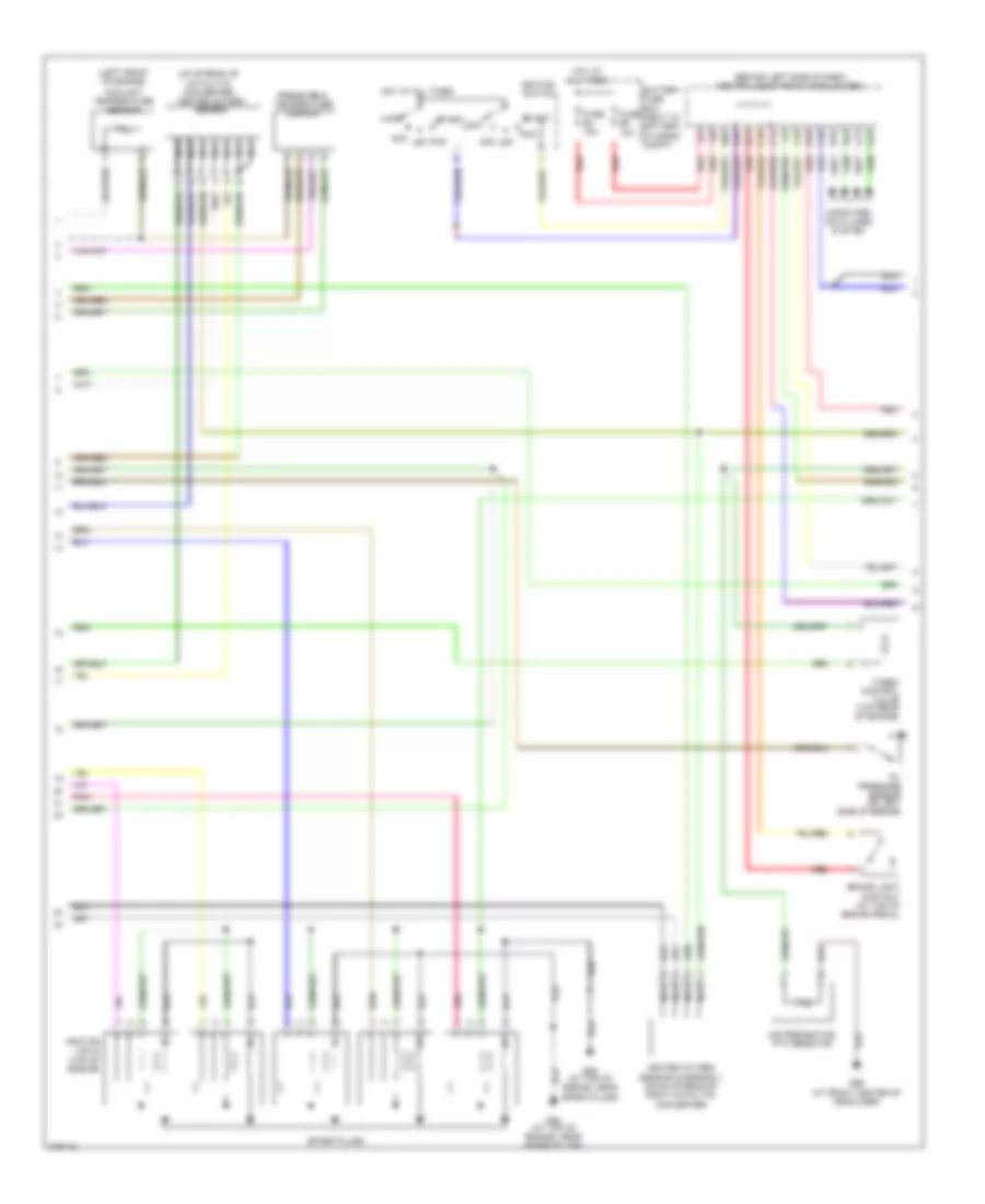 https://portal-diagnostov.com/license.html
Automotive Electricians Portal FZCO
Automotive Electricians Portal FZCO
https://portal-diagnostov.com/license.html
https://portal-diagnostov.com/license.html
Automotive Electricians Portal FZCO
Automotive Electricians Portal FZCO2.4L турбо, Электросхема системы управления двигателем (2 из 3) для Volvo V70 T-5 2005 - Список элементов:
- (behind left side of dash) central electronic module (cem)
- (left front of engine)
- (up stream of catalytic converter) heated oxygen sensor
- A16
- Acc
- Air preheating ptc resistor
- B11
- B16
- Battery fuse box (next to battery, in cargo compt)
- Brake light contact (at top of brake pedal)
- C14
- C21
- C22
- C34
- C35
- Computer data lines system
- Coolant temperature sensor
- D16
- D34
- D49
- D60
- Fuse e4 15a
- Fuse e5 10a
- G88 (at top of engine, near spark plugs)
- G89 (at top of engine, near spark plugs)
- G96 (at front center of headliner)
- Heated oxygen sensor diagnosis 1 (down stream of right catalytic converter)
- Hot at all times
- Ignition coils (top of engine)
- Ignition switch
- Lock
- Nca
- Off
- Oil pressure sensor (on left side of engine)
- Pnk
- Pressure & temperature sensor
- Red
- Run
- Spark plugs
- Start
- Turbo control valve (top rear of engine)
2.4L турбо, Электросхема системы управления двигателем (3 из 3) для Volvo V70 T-5 2005
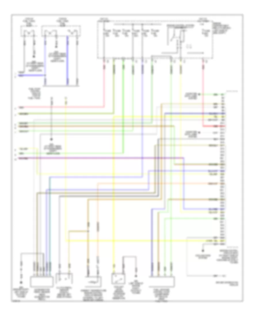 https://portal-diagnostov.com/license.html
Automotive Electricians Portal FZCO
Automotive Electricians Portal FZCO
https://portal-diagnostov.com/license.html
https://portal-diagnostov.com/license.html
Automotive Electricians Portal FZCO
Automotive Electricians Portal FZCO2.4L турбо, Электросхема системы управления двигателем (3 из 3) для Volvo V70 T-5 2005 - Список элементов:
- (top of fuel tank) fuel pump
- (v70r)
- Accelerator pedal sensor (near accelerator pedal)
- Ambient temperature engine control module sensor (integral to left rearview mirror)
- B10
- B11
- B12
- B13
- B14
- B15
- B16
- B17
- B18
- B19
- B20
- B21
- B22
- B23
- B24
- B25
- B26
- B27
- B28
- B29
- B30
- B31
- B32
- B33
- B34
- B35
- B36
- B37
- B38
- B39
- B40
- B41
- B42
- B43
- B44
- B45
- B46
- B47
- B48
- Clutch pedal sensor (manual) (behind left side of dash)
- Computer data lines system
- Coolant level sensor (on engine coolant reservoir)
- Cooling fans system
- Driver information module
- Engine compartment relay/fuse box (left side of eng compt)
- Engine control module (ecm) (at right side of engine compt, forward of strut tower)
- Engine control system main relay
- Fuel leakage control pump (under rear of vehicle, near fuel tank)
- Fuel pump control module (top of fuel tank)
- Fuse b11 20a
- Fuse b21 15a
- Fuse b23 10a
- Fuse b4 20a
- Fuse b5 15a
- Fuse b6 15a
- Fuse b8 10a
- G48 (at right rear of passenger's compt, near floor)
- G93 (engine compt, left side of on strut tower)
- G93 (left side of engine compt, on strut tower)
- Hot at all times
- Nca
- Red
2.5L ТУРБО
2.5L турбо, Электросхема системы управления двигателем (1 из 3) для Volvo V70 T-5 2005
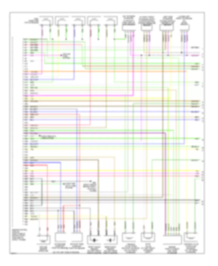 https://portal-diagnostov.com/license.html
Automotive Electricians Portal FZCO
Automotive Electricians Portal FZCO
https://portal-diagnostov.com/license.html
https://portal-diagnostov.com/license.html
Automotive Electricians Portal FZCO
Automotive Electricians Portal FZCO2.5L турбо, Электросхема системы управления двигателем (1 из 3) для Volvo V70 T-5 2005 - Список элементов:
- (at right front of engine compt) climate control system pressure sensor
- (left side of engine) intake manifold temperature sensor
- (lower left front of engine) oil level sensor
- (on top left side of engine)
- (on top rear of engine,
- (right side of engine compt, on strut tower)
- A10
- A11
- A12
- A13
- A14
- A15
- A16
- A17
- A18
- A19
- A20
- A21
- A22
- A23
- A24
- A25
- A26
- A27
- A28
- A29
- A30
- A31
- A32
- A33
- A34
- A35
- A36
- A37
- A38
- A39
- A40
- A41
- A42
- A43
- A44
- A45
- A46
- A47
- A48
- A49
- A50
- A51
- A52
- A53
- A54
- A55
- A56
- A57
- A58
- A59
- A60
- A61
- A62
- A63
- A64
- A65
- A66
- A67
- A68
- A69
- A70
- Computer data lines system
- Cooling fans system
- Engine control module (right side of engine compt, forward of strut tower)
- Engine throttle body (left side of engine)
- Evap valve (at left front of engine compt)
- Exhaust side camshaft position sensor
- Front knock sensor (on left front side of engine)
- Fuel injectors (top of engine)
- G96
- Impulse sensor (gasoline)
- In air duct) mass airflow (maf) sensor
- Intake side camshaft position sensor
- Nca
- Pnk
- Rear knock sensor (on left rear side of engine)
- Red
- Variable valve timing exhaust solenoid (on top front of engine)
- Variable valve timing inlet solenoid (at top rear of engine)
2.5L турбо, Электросхема системы управления двигателем (2 из 3) для Volvo V70 T-5 2005
 https://portal-diagnostov.com/license.html
Automotive Electricians Portal FZCO
Automotive Electricians Portal FZCO
https://portal-diagnostov.com/license.html
https://portal-diagnostov.com/license.html
Automotive Electricians Portal FZCO
Automotive Electricians Portal FZCO2.5L турбо, Электросхема системы управления двигателем (2 из 3) для Volvo V70 T-5 2005 - Список элементов:
- (behind left side of dash) central electronic module (cem)
- (left front of engine)
- (up stream of catalytic converter) heated oxygen sensor
- A16
- Acc
- Air preheating ptc resistor
- B11
- B16
- Battery fuse box (next to battery, in cargo compt)
- Brake light contact (at top of brake pedal)
- C14
- C21
- C22
- C34
- C35
- Computer data lines system
- Coolant temperature sensor
- D16
- D34
- D49
- D60
- Fuse e4 15a
- Fuse e5 10a
- G88 (at top of engine, near spark plugs)
- G89 (at top of engine, near spark plugs)
- G96 (at front center of headliner)
- Heated oxygen sensor diagnosis 1 (down stream of right catalytic converter)
- Hot at all times
- Ignition coils (top of engine)
- Ignition switch
- Lock
- Nca
- Off
- Oil pressure sensor (on left side of engine)
- Pnk
- Pressure & temperature sensor
- Red
- Run
- Spark plugs
- Start
- Turbo control valve (top rear of engine)
2.5L турбо, Электросхема системы управления двигателем (3 из 3) для Volvo V70 T-5 2005
 https://portal-diagnostov.com/license.html
Automotive Electricians Portal FZCO
Automotive Electricians Portal FZCO
https://portal-diagnostov.com/license.html
https://portal-diagnostov.com/license.html
Automotive Electricians Portal FZCO
Automotive Electricians Portal FZCO2.5L турбо, Электросхема системы управления двигателем (3 из 3) для Volvo V70 T-5 2005 - Список элементов:
- (top of fuel tank) fuel pump
- (v70r)
- Accelerator pedal sensor (near accelerator pedal)
- Ambient temperature engine control module sensor (integral to left rearview mirror)
- B10
- B11
- B12
- B13
- B14
- B15
- B16
- B17
- B18
- B19
- B20
- B21
- B22
- B23
- B24
- B25
- B26
- B27
- B28
- B29
- B30
- B31
- B32
- B33
- B34
- B35
- B36
- B37
- B38
- B39
- B40
- B41
- B42
- B43
- B44
- B45
- B46
- B47
- B48
- Clutch pedal sensor (manual) (behind left side of dash)
- Computer data lines system
- Coolant level sensor (on engine coolant reservoir)
- Cooling fans system
- Driver information module
- Engine compartment relay/fuse box (left side of eng compt)
- Engine control module (ecm) (at right side of engine compt, forward of strut tower)
- Engine control system main relay
- Fuel leakage control pump (under rear of vehicle, near fuel tank)
- Fuel pump control module (top of fuel tank)
- Fuse b11 20a
- Fuse b21 15a
- Fuse b23 10a
- Fuse b4 20a
- Fuse b5 15a
- Fuse b6 15a
- Fuse b8 10a
- G48 (at right rear of passenger's compt, near floor)
- G93 (engine compt, left side of on strut tower)
- G93 (left side of engine compt, on strut tower)
- Hot at all times
- Nca
- Red
СИСТЕМА УСИЛИТЕЛЯ РУЛЯ
Электросхема усилителя руля для Volvo V70 T-5 2005
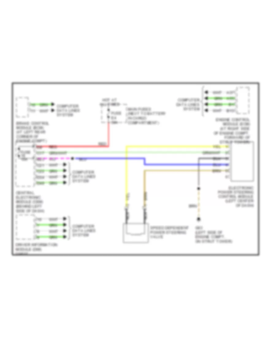 https://portal-diagnostov.com/license.html
Automotive Electricians Portal FZCO
Automotive Electricians Portal FZCO
https://portal-diagnostov.com/license.html
https://portal-diagnostov.com/license.html
Automotive Electricians Portal FZCO
Automotive Electricians Portal FZCOЭлектросхема усилителя руля для Volvo V70 T-5 2005 - Список элементов:
- A37
- A55
- B13
- B23
- Brake control module (bcm) (at left rear corner of engine compt)
- C17
- C21
- C22
- Central electronic module (cem) (behind left side of dash)
- Computer data lines system
- D34
- D49
- Driver information module (dim)
- Electronic power steering control module (left center of dash)
- Engine control module (ecm) (at right side of engine compt, forward of strut tower)
- Fuse 10a
- Fuse e4 50a
- G93 (left side of engine compt, on strut tower)
- Hot at all times
- Main fuses (next to battery in cargo compartment)
- Nca
- Red
- Speed dependent power steering valve
Система Фар
Электросхема фар, С ксеноновые лампы для Volvo V70 T-5 2005
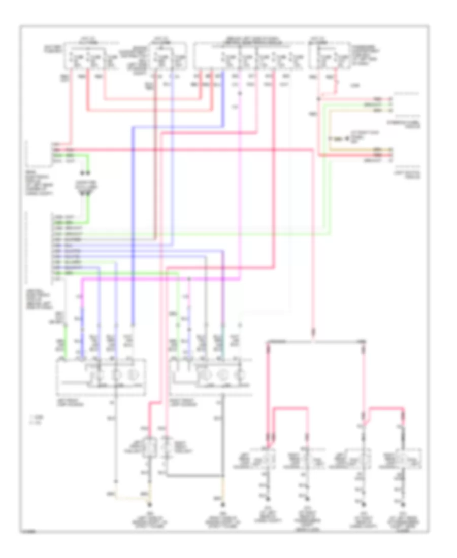 https://portal-diagnostov.com/license.html
Automotive Electricians Portal FZCO
Automotive Electricians Portal FZCO
https://portal-diagnostov.com/license.html
https://portal-diagnostov.com/license.html
Automotive Electricians Portal FZCO
Automotive Electricians Portal FZCOЭлектросхема фар, С ксеноновые лампы для Volvo V70 T-5 2005 - Список элементов:
- (at right kick panel) g84
- (behind left side of dash) central electronic module
- A6 nca
- B17
- B18
- B23
- B27
- B28
- Battery fuse box
- C13
- C14
- Central electronic module (behind left side of dash)
- Computer data lines system
- D35
- D41
- D50
- D58
- Dip
- Drl
- Engine compartment distribution box (left side of engine compt)
- Fog light
- Fuse 10a
- Fuse 7.5a
- Fuse b17 20a
- Fuse b20 20a
- Fuse c10 5a
- Fuse c9 5a
- Fuse e1 60a
- Fuse e4 50a
- Fuse e5 50a
- G72 (at left rear of cargo compt)
- G72 (at right rear of cargo compt)
- G73 (at left rear of passenger's compt, near floor)
- G73 (at right rear of passenger's compt, near floor)
- G93 (left side of engine compt, on strut tower)
- G94 (right side of engine compt, on strut tower)
- Hot at all times
- Left front foglight
- Left front lamp housing
- Left rear lamp housing
- Light switch module
- Main
- Nca
- Passenger compartment fuse box (at left end of dash)
- Pnk
- Rear electronic module (at left rear corner of cargo compt)
- Red
- Right front foglight
- Right front lamp housing
- Right rear lamp housing
- Steering wheel module
- V70
- V70/xc70
- Xc90
Электросхема фар, без Ксеноновые лампы для Volvo V70 T-5 2005
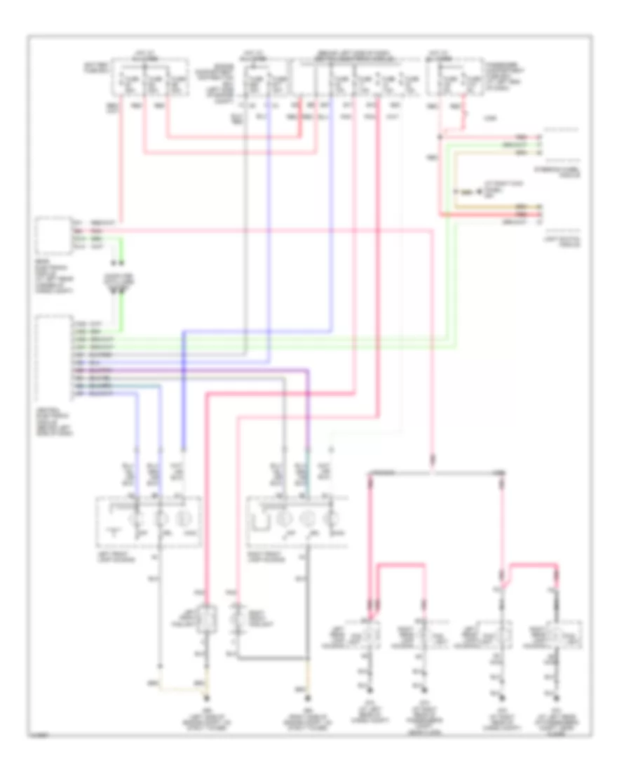 https://portal-diagnostov.com/license.html
Automotive Electricians Portal FZCO
Automotive Electricians Portal FZCO
https://portal-diagnostov.com/license.html
https://portal-diagnostov.com/license.html
Automotive Electricians Portal FZCO
Automotive Electricians Portal FZCOЭлектросхема фар, без Ксеноновые лампы для Volvo V70 T-5 2005 - Список элементов:
- (at right kick panel) g84
- (behind left side of dash) central electronic module
- A6 nca
- B17
- B18
- B27
- B28
- Battery fuse box
- C13
- C14
- Central electronic module (behind left side of dash)
- Computer data lines system
- D35
- D41
- D50
- D58
- Dip
- Drl
- Engine compartment distribution box (left side of engine compt)
- Fog light
- Fuse 10a
- Fuse 7.5a
- Fuse b17 20a
- Fuse b20 20a
- Fuse c10 5a
- Fuse c9 5a
- Fuse e1 60a
- Fuse e4 50a
- Fuse e5 50a
- G72 (at left rear of cargo compt)
- G72 (at right rear of cargo compt)
- G73 (at left rear of passenger's compt, near floor)
- G73 (at right rear of passenger's compt, near floor)
- G93 (left side of engine compt, on strut tower)
- G94 (right side of engine compt, on strut tower)
- Hot at all times
- Left front foglight
- Left front lamp housing
- Left rear lamp housing
- Light switch module
- Main
- Nca
- Passenger compartment fuse box (at left end of dash)
- Pnk
- Rear electronic module (at left rear corner of cargo compt)
- Red
- Right front foglight
- Right front lamp housing
- Right rear lamp housing
- Steering wheel module
- V70/xc70
- Xc90
СИСТЕМЫ ПАМЯТИ
Электросхема памяти водительского сиденья для Volvo V70 T-5 2005
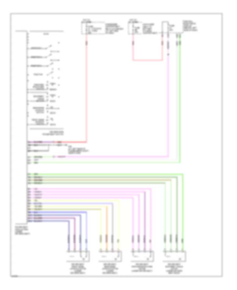 https://portal-diagnostov.com/license.html
Automotive Electricians Portal FZCO
Automotive Electricians Portal FZCO
https://portal-diagnostov.com/license.html
https://portal-diagnostov.com/license.html
Automotive Electricians Portal FZCO
Automotive Electricians Portal FZCOЭлектросхема памяти водительского сиденья для Volvo V70 T-5 2005 - Список элементов:
- (v70/xc70) (xc90)
- A10
- B10
- B11
- B12
- Back
- Backrest angle switch
- Central electronic module (behind left side of dash)
- D36
- D51
- Down
- Driver seat backrest angle motor (under driver's seat back)
- Driver seat forward/backward motor (under driver seat)
- Driver seat front edge up/down motor (under driver's seat)
- Driver seat rear edge up/down motor (under driver's seat)
- Driver's side power seat switch
- Forw
- Forward/ backward switch
- Front edge up/down switch
- Fuse 20a
- Fuse c1 c3 25a
- Fuse e5 50a
- G46 (at left rear of passenger's compt, near floor)
- Hot at all times
- Main fuses (next to battery in cargo compartment)
- Passenger compartment relay & fuse box (at left end of dash)
- Position
- Position 1
- Position 2
- Position 3
- Power seat module (psm) (under driver's seat)
- Rear edge up/down switch
- Rearw
- Red
Электросхем памяти регулировки зеркал заднего вида для Volvo V70 T-5 2005
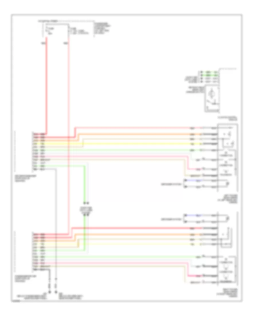 https://portal-diagnostov.com/license.html
Automotive Electricians Portal FZCO
Automotive Electricians Portal FZCO
https://portal-diagnostov.com/license.html
https://portal-diagnostov.com/license.html
Automotive Electricians Portal FZCO
Automotive Electricians Portal FZCOЭлектросхем памяти регулировки зеркал заднего вида для Volvo V70 T-5 2005 - Список элементов:
- (xc90) (v70/xc70)
- 10a
- A10
- A11
- A25
- A26
- A27
- A28
- A29
- B12
- Climate control module
- Computer data lines system
- Defogger system
- Driver/passenger door module (ddm/pdm)
- Fold-back
- Fuse 25a
- G66 (below driver's seat, near rocker panel)
- G67 (below passenger's seat, near rocker panel)
- Hot at all times
- Left power door mirror (in left rearview mirror)
- Nca
- Passenger compartment fuse box (at left end of dash)
- Passenger/driver door module (pdm/ddm)
- Pnk
- Red
- Retractable rear-view mirrors switch
- Right power door mirror (in right rearview mirror)
- X-direction
- Y-direction
СИСТЕМЫ ПОДВЕСКИ
Электросхема электроники подвески для Volvo V70 T-5 2005
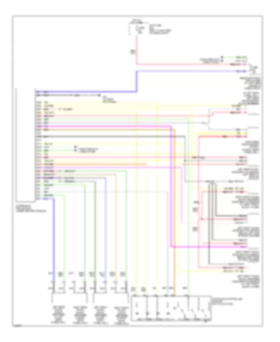 https://portal-diagnostov.com/license.html
Automotive Electricians Portal FZCO
Automotive Electricians Portal FZCO
https://portal-diagnostov.com/license.html
https://portal-diagnostov.com/license.html
Automotive Electricians Portal FZCO
Automotive Electricians Portal FZCOЭлектросхема электроники подвески для Volvo V70 T-5 2005 - Список элементов:
- (in left rear wheelwell) left rear angle sensor (four-c/bi-xenon)
- A10
- A11
- A12
- A13
- A14
- A15
- A16
- A17
- A18
- A19
- A20
- A21
- A22
- A23
- A24
- A25
- A26
- A27
- A28
- A29
- A30
- C13
- C14
- Computer data lines system
- Continuous controlled damping switch unit(ccd)
- Fuse e1 60a
- Fuse f24 15a
- G10 (at right kick panel)
- Hot at all times
- Left front four-c acceleration sensor (behind left side of front bumper)
- Left front four-c shock absorber (in left front wheelwell)
- Left front four-c shock absorber acceleration sensor (at left front shock tower)
- Left rear four-c acceleration sensor (left rear of vehicle)
- Left rear four-c shock absorber (in left rear wheelwell)
- Main fuse box (next to battery, in cargo compt)
- Nca
- Pnk
- Rear electronic module (rem) (at left rear corner of cargo compt)
- Red
- Right front four-c acceleration sensor (behind right side of front bumper)
- Right front four-c shock absorber (in right front wheelwell)
- Right front four-c shock absorber acceleration sensor (at right front shock tower)
- Right rear angle sensor (four-c) (in right rear wheelwell)
- Right rear four-c shock absorber (in right rear wheelwell)
- Suspension module (sum) (under center console)
СИСТЕМЫ СИДЕНИЙ
Электросхема привода водительского сиденья для Volvo V70 T-5 2005
 https://portal-diagnostov.com/license.html
Automotive Electricians Portal FZCO
Automotive Electricians Portal FZCO
https://portal-diagnostov.com/license.html
https://portal-diagnostov.com/license.html
Automotive Electricians Portal FZCO
Automotive Electricians Portal FZCOЭлектросхема привода водительского сиденья для Volvo V70 T-5 2005 - Список элементов:
- (v70/xc70) (xc90)
- A10
- B10
- B11
- B12
- Back
- Backrest angle switch
- Central electronic module (behind left side of dash)
- D36
- D51
- Down
- Driver seat backrest angle motor (under driver's seat back)
- Driver seat forward/backward motor (under driver seat)
- Driver seat front edge up/down motor (under driver's seat)
- Driver seat rear edge up/down motor (under driver's seat)
- Driver's side power seat switch
- Forw
- Forward/ backward switch
- Front edge up/down switch
- Fuse 20a
- Fuse c1 c3 25a
- Fuse e5 50a
- G46 (at left rear of passenger's compt, near floor)
- Hot at all times
- Main fuses (next to battery, in cargo compt.)
- Passenger compartment relay & fuse box (at left end of dash)
- Position
- Position 1
- Position 2
- Position 3
- Power seat module (psm) (under driver's seat)
- Rear edge up/down switch
- Rearw
- Red
Электросхема подогрева сидений для Volvo V70 T-5 2005
 https://portal-diagnostov.com/license.html
Automotive Electricians Portal FZCO
Automotive Electricians Portal FZCO
https://portal-diagnostov.com/license.html
https://portal-diagnostov.com/license.html
Automotive Electricians Portal FZCO
Automotive Electricians Portal FZCOЭлектросхема подогрева сидений для Volvo V70 T-5 2005 - Список элементов:
- A10
- A11
- A12
- A18
- A19
- Air conditioning system
- Backrest heater
- Battery fuse box
- Central electronic module (behind left side of dash)
- Climate control module
- Computer data lines system
- Fuse 15a
- Fuse e4 50a
- G46 (at left rear of passenger's compt, near floor)
- G67 (below passenger's seat, near rocker panel)
- Hot at all times
- Left heated seat switch
- Left seat heater module (under left front seats)
- Nca
- Red
- Right heated seat switch
- Right seat heater module (under right front seats)
- Seat heater
- Temperature sensor
Электросхема привода пассажирского сиденья для Volvo V70 T-5 2005
 https://portal-diagnostov.com/license.html
Automotive Electricians Portal FZCO
Automotive Electricians Portal FZCO
https://portal-diagnostov.com/license.html
https://portal-diagnostov.com/license.html
Automotive Electricians Portal FZCO
Automotive Electricians Portal FZCOЭлектросхема привода пассажирского сиденья для Volvo V70 T-5 2005 - Список элементов:
- (under front passenger's seat) passenger backrest angle seat motor
- (under front passenger's seat) passenger forward/ backward seat motor
- (under front passenger's seat) passenger up/down front edge seat motor
- (under front passenger's seat) passenger up/down rear edge seat motor
- A22
- Back
- Backrest switch
- Central electronic module (behind left side of dash)
- Down
- Forw
- Forward/ backward switch
- Front edge up/down switch
- Fuse 5a
- Fuse c2 c4 25a
- Fuse e4 50a
- G67 (below passenger's seat, near rocker panel)
- Hot at all times
- Main fuses (next to battery, in cargo compt.)
- Passenger compartment fuse box (at left end of dash)
- Power passenger seat module
- Rear edge up/down switch
- Red
- Stop logic
- V70/xc70
- Xc90
Стартер Генератор
Электросхема Генератора для Volvo V70 T-5 2005
 https://portal-diagnostov.com/license.html
Automotive Electricians Portal FZCO
Automotive Electricians Portal FZCO
https://portal-diagnostov.com/license.html
https://portal-diagnostov.com/license.html
Automotive Electricians Portal FZCO
Automotive Electricians Portal FZCOЭлектросхема Генератора для Volvo V70 T-5 2005 - Список элементов:
- (left side of engine compartment) auxiliary start connection
- Battery
- C16
- C21
- C22
- Central electronic module (behind left side of dash)
- Computer data lines system
- D34
- D49
- Engine compartment relay/fuse box (at left side of engine compartment, forward of strut tower)
- G53 (left side of engine compt)
- Generator
- Instrument cluster
- Main fuses (next to battery, in cargo compt)
- Power distribution system
- Red
- Starter motor
Электросхема стартера для Volvo V70 T-5 2005
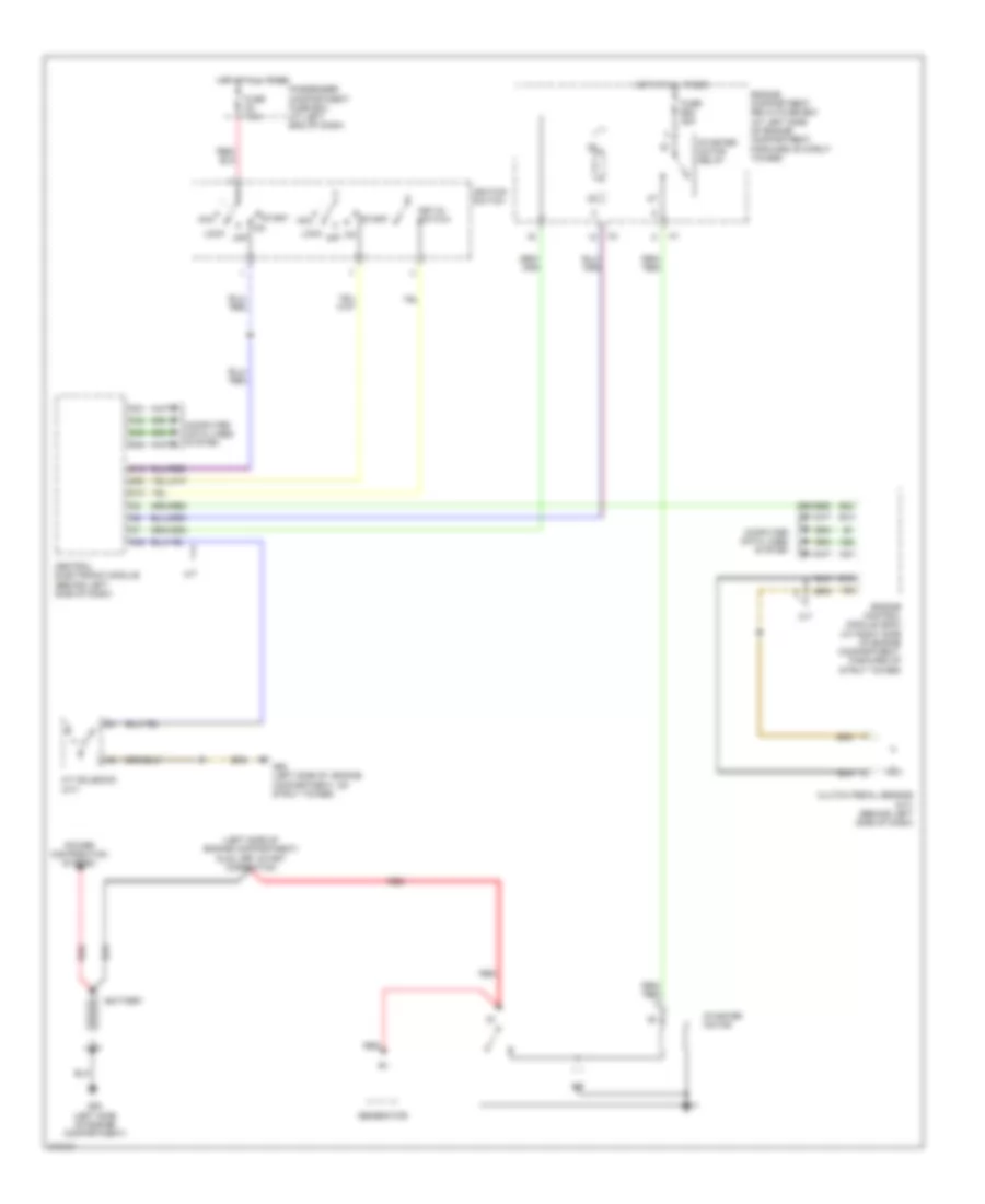 https://portal-diagnostov.com/license.html
Automotive Electricians Portal FZCO
Automotive Electricians Portal FZCO
https://portal-diagnostov.com/license.html
https://portal-diagnostov.com/license.html
Automotive Electricians Portal FZCO
Automotive Electricians Portal FZCOЭлектросхема стартера для Volvo V70 T-5 2005 - Список элементов:
- (a/t)
- (left side of engine compartment) auxiliary start connection
- A/t
- A/t solenoid
- A37
- A55
- Acc
- B13
- B15
- B23
- Battery
- C21
- C22
- C28
- Central electronic module (behind left side of dash)
- Clutch pedal sensor (m/t) (behind left side of dash)
- Computer data lines system
- D15
- D16
- D34
- D49
- D60
- Engine compartment relay/fuse box (at left side of engine compartment, forward of strut tower)
- Engine control module (ecm) (at right side of engine compartment, forward of strut tower)
- Fuse b22 35a
- Fuse c8 7.5a
- G53 (left side of engine compartment)
- G93 (left side of engine compartment, on strut tower)
- Generator
- Hot at all times
- Ignition switch
- Key-in switch
- Lock
- M/t
- Off
- Passenger compartment fuse box (at left end of dash)
- Power distribution system
- Red
- Start
- Starter motor
- Starter motor relay
Стеклоочистители и Стеклоомыватели Дворники
Электросхема передних стеклоочистителей дворников и омывателя лобового стекла для Volvo V70 T-5 2005
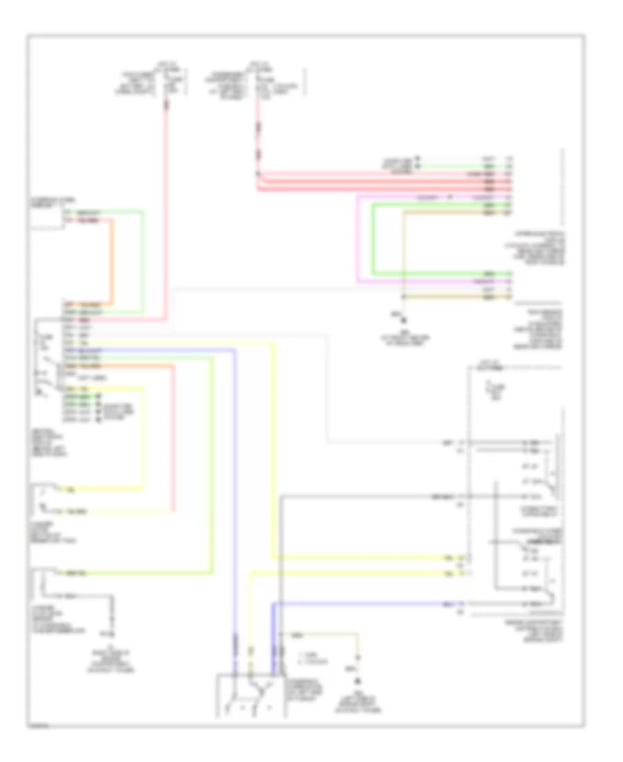 https://portal-diagnostov.com/license.html
Automotive Electricians Portal FZCO
Automotive Electricians Portal FZCO
https://portal-diagnostov.com/license.html
https://portal-diagnostov.com/license.html
Automotive Electricians Portal FZCO
Automotive Electricians Portal FZCOЭлектросхема передних стеклоочистителей дворников и омывателя лобового стекла для Volvo V70 T-5 2005 - Список элементов:
- (not used)
- (v70/xc70) (xc90)
- (xc90)
- 87a
- B21
- B29
- B30
- C10
- C31
- Central electronic module (behind left side of dash)
- Computer data lines system
- D11
- D34
- D35
- D49
- D50
- D58
- Engine compartment distribution box (left side of engine compt)
- Fuse 15a
- Fuse b13 25a
- Fuse c6 c12 10a
- Fuse e5 50a
- G1 (right side of engine compartment, on strut tower)
- G93 (left side of engine compt, on strut tower)
- G98 (at front center of headliner)
- Hot at all times
- Intermittent wiping relay
- Main fuses (next to battery, in cargo compt)
- Passenger compartment fuse box (at left end of dash)
- Rain sensor module (if equipped) (above center of windshield, forward of rearview mirror)
- Red
- Steering wheel module
- Upper electronic module (v70/xc70: integral to rearview mirror xc90: rearward of roof console)
- V70/xc70
- Washer fluid level sensor (in windshield washer reservoir)
- Washer motor (bottom of reservoir tank)
- Windshield wiper low/high speed relay
- Windshield wiper motor (on left side of plenum)
- Xc90
схема шайбы высокого давления фары для Volvo V70 T-5 2005
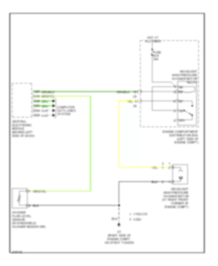 https://portal-diagnostov.com/license.html
Automotive Electricians Portal FZCO
Automotive Electricians Portal FZCO
https://portal-diagnostov.com/license.html
https://portal-diagnostov.com/license.html
Automotive Electricians Portal FZCO
Automotive Electricians Portal FZCOсхема шайбы высокого давления фары для Volvo V70 T-5 2005 - Список элементов:
- 87a
- C10
- C25
- Central electronic module (behind left side of dash)
- Computer data lines system
- D34
- D35
- D49
- D50
- Engine compartment distribution box (left side of engine compt)
- Fuse b15 35a
- G1 (right side of engine compt, on strut tower)
- Headlight high pressure washer motor (at right front corner of engine compt)
- Headlight high pressure washer motor relay
- Hot at all times
- V70/xc70
- Washer fluid level sensor (in windshield washer reservoir)
- Xc90
Электросхема стеклоочистителя, дворников и омывателя Фары для Volvo V70 T-5 2005
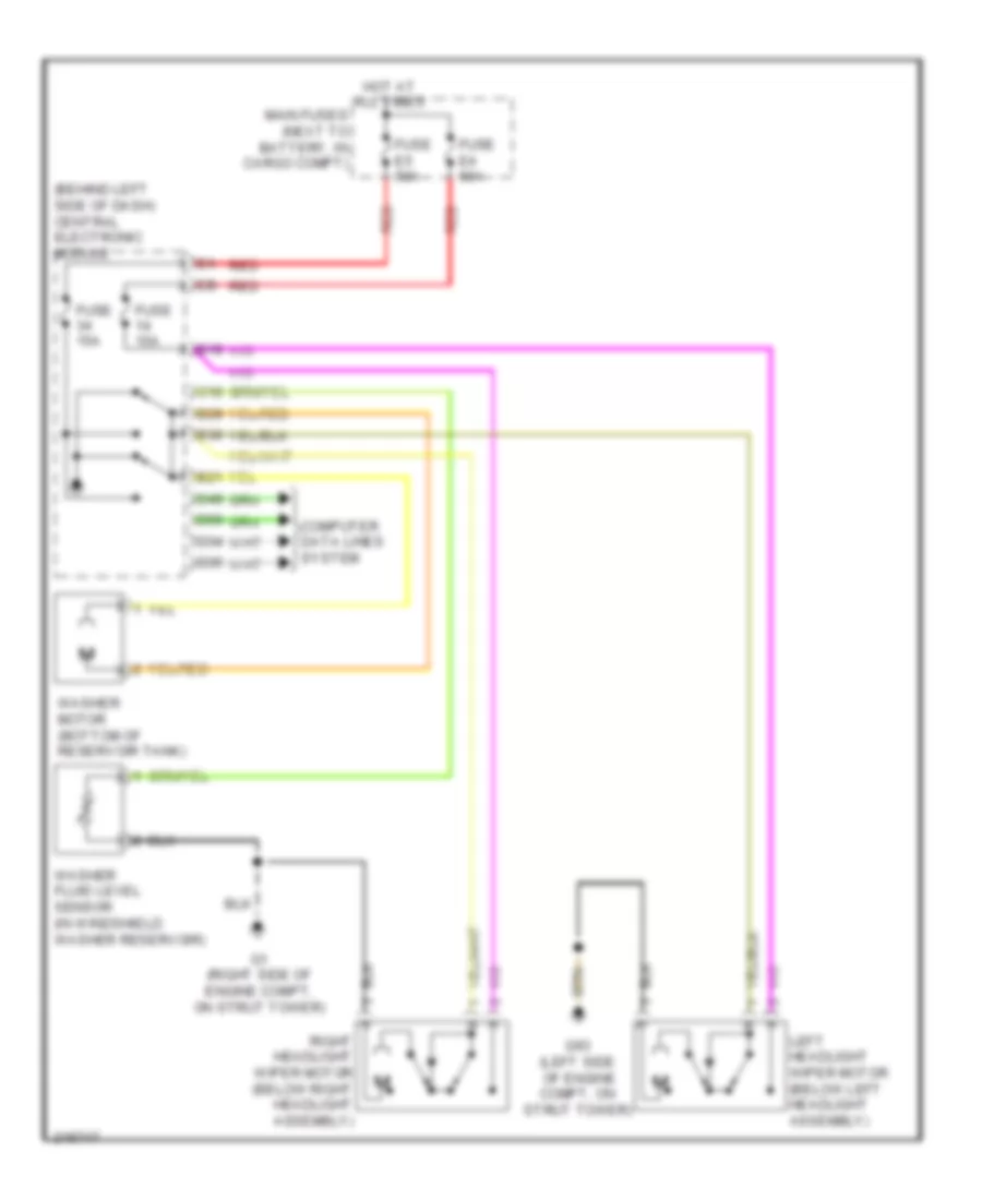 https://portal-diagnostov.com/license.html
Automotive Electricians Portal FZCO
Automotive Electricians Portal FZCO
https://portal-diagnostov.com/license.html
https://portal-diagnostov.com/license.html
Automotive Electricians Portal FZCO
Automotive Electricians Portal FZCOЭлектросхема стеклоочистителя, дворников и омывателя Фары для Volvo V70 T-5 2005 - Список элементов:
- (behind left side of dash) central electronic module
- B19
- B21
- B29
- B30
- C10
- Computer data lines system
- D34
- D35
- D49
- D50
- Fuse 15a
- Fuse e4 50a
- Fuse e5 50a
- G1 (right side of engine compt, on strut tower)
- G93 (left side of engine compt, on strut tower)
- Hot at all times
- Left headlight wiper motor (below left headlight assembly)
- Main fuses (next to battery, in cargo compt)
- Red
- Right headlight wiper motor (below right headlight assembly)
- Washer fluid level sensor (in windshield washer reservoir)
- Washer motor (bottom of reservoir tank)
Электросхема заднего стеклоочистителя дворника и омывателя для Volvo V70 T-5 2005
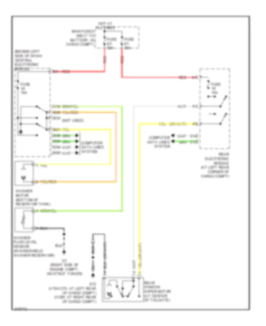 https://portal-diagnostov.com/license.html
Automotive Electricians Portal FZCO
Automotive Electricians Portal FZCO
https://portal-diagnostov.com/license.html
https://portal-diagnostov.com/license.html
Automotive Electricians Portal FZCO
Automotive Electricians Portal FZCOЭлектросхема заднего стеклоочистителя дворника и омывателя для Volvo V70 T-5 2005 - Список элементов:
- (behind left side of dash) central electronic module
- (not used)
- B21
- B29
- B30
- C10
- C13
- C14
- Computer data lines system
- D34
- D35
- D49
- D50
- Fuse 15a
- Fuse e1 60a
- Fuse e5 50a
- G1 (right side of engine compt, on strut tower)
- G72 (v70/xc70: at left rear of cargo compt) (xc90: at right rear of cargo compt)
- Hot at all times
- Main fuses (next to battery, in cargo compt)
- Rear electronic module (at left rear corner of cargo compt)
- Rear window wiper motor (at center of tailgate)
- Red
- Washer fluid level sensor (in windshield washer reservoir)
- Washer motor (bottom of reservoir tank)
ЦЕНТРАЛЬНЫЙ ЗАМОК
Электросхема центрального замка (1 из 2) для Volvo V70 T-5 2005
 https://portal-diagnostov.com/license.html
Automotive Electricians Portal FZCO
Automotive Electricians Portal FZCO
https://portal-diagnostov.com/license.html
https://portal-diagnostov.com/license.html
Automotive Electricians Portal FZCO
Automotive Electricians Portal FZCOЭлектросхема центрального замка (1 из 2) для Volvo V70 T-5 2005 - Список элементов:
- (below passenger's seat near rocker panel) g67
- A10
- A11
- A12
- A13
- B12
- Bll
- Climate control module
- Computer data lines system
- Driver door module (ddm)
- Fuse c4 25a
- Fuse c5 25a
- G66 (below driver's seat near rocker panel)
- Hot at all times
- Key
- Left front door lock unit (rear of left front door)
- Lock
- Passenger compartment fuse box (at left end of dash)
- Passenger door module (pdm)
- Pcl child lock safety switch
- Pnk
- Red
- Right front door lock unit (rear of right front door)
- Tailgate private locking switch
- Unlock
- Upper electronic module (integral to rearview mirror)
Электросхема центрального замка (2 из 2) для Volvo V70 T-5 2005
 https://portal-diagnostov.com/license.html
Automotive Electricians Portal FZCO
Automotive Electricians Portal FZCO
https://portal-diagnostov.com/license.html
https://portal-diagnostov.com/license.html
Automotive Electricians Portal FZCO
Automotive Electricians Portal FZCOЭлектросхема центрального замка (2 из 2) для Volvo V70 T-5 2005 - Список элементов:
- (not used)
- (w/ power child lock)
- A19
- A23
- A24
- A27
- B12
- B24
- B26
- B30
- Battery fuse box (next to battery, in cargo compt)
- Bll
- C10
- C12
- C13
- C14
- Central electronic module (cem) (behind left side of dash)
- Computer data lines system
- D15
- D28
- D29
- D33
- D34
- D35
- D38
- D39
- D49
- D50
- D53
- D54
- Exterior lights system
- Fuel filler cover lock motor (right side of cargo compt, behind carpet)
- Fuse e1 60a
- Fuse f10 15a
- Fuse f28 15a
- Fuse f9 20a
- G46 (at left rear of passenger's compt, near floor)
- G67 (below passenger's seat near rocker panel)
- G72 (at left rear of cargo compt)
- Hot at all times
- Ignition switch
- Key in
- Key in ignition
- Left rear door deadlock relay (in left rear door)
- Left rear door lock unit (rear of left rear door)
- Left rear door power window switch
- Pcl
- Pnk
- Rear electronic module (rem) (at left rear corner of cargo compt)
- Right rear door deadlock relay (in right rear door)
- Right rear door lock unit (rear of right rear door)
- Right rear door power window switch
- Tailgate glass breakage sensor (in tailgate window)
- Tailgate lock unit (bottom rear of tailgate)
- V70 & xc70
- W/ power child lock
- Xc90

 Čeština
 Dansk
Dansk Deutsch
 Ελληνικά
 English
 English
 Español
 Suomi
Suomi Français
 Français
 עברית
עברית Hrvatski
 Magyar
 Italiano
 日本語
日本語 Nederlands
 Polski
 Português
 Português
 Română
 Русский
 Slovenčina
 Slovenščina
 Svenska
 Türkçe
 中文 (中国)
