WARNING SYSTEMS
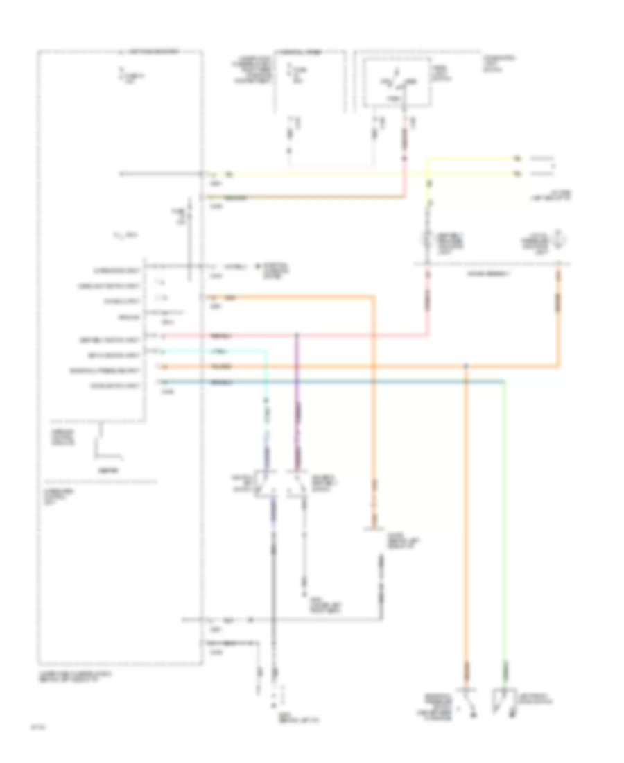
Warning Systems Wiring Diagram for Acura Integra GS-R 1994
List of elements for Warning Systems Wiring Diagram for Acura Integra GS-R 1994:
- Alternator input
- Beeper
- C215
- C436
- C439
- C440
- C446
- C551
- C914
- Chime (behind left side of i/p)
- Chime output
- Combination light switch
- D11
- Door switch input
- Driver's seat belt switch
- Engine oil pressure input
- Engine oil pressure switch (center rear of engine)
- Fuse 10a
- Fuse 15 10a
- Fuse 50a
- G202 (behind left i/p)
- G300 (under left front seat)
- Gauge assembly
- Ground
- Head
- Head- light switch
- Headlight switch input
- Hot at all times
- Hot in on or start
- Ignition key switch
- Integrated control unit
- J/c c556 (left end of i/p)
- Key in ignition input
- Left front door switch
- Low oil pressure indicator light
- Off
- Park
- Seat belt reminder indicator light
- Seat belt switch input
- Starting/ charging system
- Under-dash fuse/relay box (behind left side of i/p)
- Under-hood fuse/relay box (right rear of engine compartment)
- Warning control circuits
 English