AUTOMOTIVE ELECTRICIANS PORTAL

WARNING SYSTEMS – Acura RL 2012 – SYSTEM WIRING DIAGRAMS

WARNING SYSTEMS

Chime Wiring Diagram for Acura RL 2012

Chime Wiring Diagram for Acura RL 2012 https://portal-diagnostov.com/license.html
https://portal-diagnostov.com/license.html Automotive Electricians Portal FZCO Automotive Electricians Portal FZCO
Download PDF file

List of elements for Chime Wiring Diagram for Acura RL 2012:

  • (not used)
  • 10v regulator
  • A11
  • A13
  • A16
  • A17
  • A28
  • A48
  • A49
  • Auto
  • B-can
  • B-can door sw (dr)
  • B12
  • B15
  • B16
  • B17
  • B19
  • B20
  • Beeper
  • Body controller area network transceiver
  • C102
  • C45
  • C601
  • C604
  • C751
  • C752
  • C754
  • C901
  • Can h
  • Can l
  • Canh
  • Canl switch input opsw
  • Combination light switch
  • Combination switch control unit
  • Computer data lines system
  • Door & trunk open monitor
  • Drive circuit
  • Driver's door switch
  • Driver's mpcs unit (in driver's door)
  • Driver's seat belt buckle switch (under driver's seat)
  • Driver's seat belt tension reducer solenoid (on base of left "b" pillar)
  • Driver's under-dash fuse/relay box (behind left kick panel)
  • F14
  • Fan control area network tranceiver
  • Fuse 10a
  • G501 (under left side of dash)
  • G502 (under left side of dash)
  • G601 (at left side of floor)
  • Gauge control module
  • H14
  • Head
  • Headlight switch
  • Hot at all times
  • Hot in on or start
  • Ignition key light
  • Ignition key switch
  • Ignition switch control unit
  • J/c c510 (behind left side of dash)
  • J/c c512 (behind left side of dash)
  • J/c c520 (under steering column cover)
  • J/c c607 (behind left kick panel)
  • J/c c608 (behind left kick panel)
  • J/c c610 (on base of left "b" pillar)
  • J/c c757 (in driver's door)
  • Key lt
  • Key sw
  • Keyless access control unit (under left side of dash)
  • Lbsc
  • Lbso
  • Left rear door lock actuator/knob switch/door switch (rear of left rear door)
  • Lights on ind
  • Lights on/fog light brightness control and dimming circuit
  • Low oil pressure ind
  • Micu
  • Multi-information display(mid) unit
  • N22
  • N28
  • Off
  • Oil pressure switch (right side of engine)
  • Park
  • Pcm (under middle of dash)
  • Pnk
  • Red
  • Seat belt reminder ind
  • Sg-1
  • Sg-2
  • Srs unit (under lower middle of dash)
  • Wiper/washer switch
  • X18
  • X34
  • X35

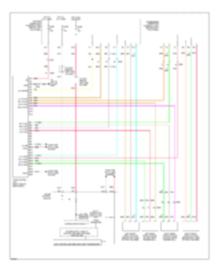
Tire Pressure Monitoring Wiring Diagram for Acura RL 2012

Tire Pressure Monitoring Wiring Diagram for Acura RL 2012 https://portal-diagnostov.com/license.html
https://portal-diagnostov.com/license.html Automotive Electricians Portal FZCO Automotive Electricians Portal FZCO
모든 배선 다이어그램에 액세스하십시오.Download PDF file

List of elements for Tire Pressure Monitoring Wiring Diagram for Acura RL 2012:

  • (in left ''c'' pillar) g602
  • A10
  • A11
  • A12
  • A13
  • A14
  • B10
  • B11
  • B12
  • B13
  • B14
  • B15
  • B16
  • B17
  • B18
  • B19
  • B20
  • C10
  • C601
  • C606
  • C656
  • Canh
  • Canl
  • Computer data lines system
  • Driver's under-dash fuse/relay box (behind left kick panel)
  • E12
  • Fast controller area network transceiver
  • Fuse 10a
  • Fuse 7.5a
  • Gauge control module
  • Gnd
  • Hot at all times
  • Hot in on or start
  • Ig1 meter
  • J/c c510 (behind left side of dash)
  • J/c c512 (behind left side of dash)
  • K-line
  • Left front tpms initiator (behind left side of front bumper)
  • Left rear tpms initiator (on left rear fenderwell)
  • Lf lf gnd
  • Lf lf pwr
  • Lf lf sig
  • Low tire- pressure indicator
  • Lr lf gnd
  • Lr lf pwr
  • Lr lf sig
  • Multi- information display (mid) unit
  • Passenger's under-dash fuse/relay box (behind right kick panel)
  • Pnk
  • Red
  • Rf lf gnd
  • Rf lf pwr
  • Rf lf sig
  • Right front tpms initiator (behind right side of front bumper)
  • Right rear tpms initiator (on right rear fenderwell)
  • Rr lf gnd
  • Rr lf pwr
  • Rr lf sig
  • Tpms control unit (right side of rear shelf)
  • Tpms indicator
  • Warning drive circuit
  • X12
  • X34
  • X35