WARNING SYSTEMS
Chime Wiring Diagram for Acura TL SH-AWD 2010

List of elements for Chime Wiring Diagram for Acura TL SH-AWD 2010:
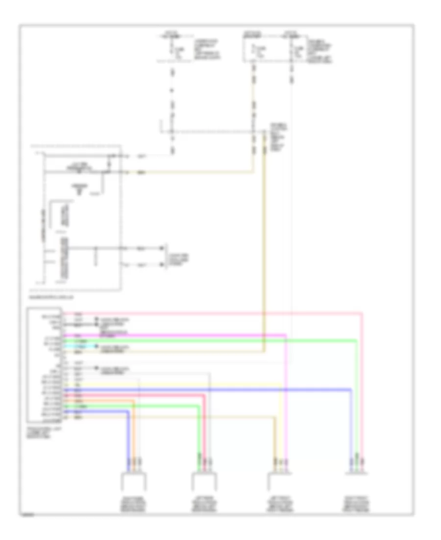
Tire Pressure Monitoring Wiring Diagram for Acura TL SH-AWD 2010
List of elements for Tire Pressure Monitoring Wiring Diagram for Acura TL SH-AWD 2010: