AUTOMOTIVE ELECTRICIANS PORTAL

WARNING SYSTEMS – Acura TSX 2011 – SYSTEM WIRING DIAGRAMS

WARNING SYSTEMS

Chime Wiring Diagram for Acura TSX 2011

Chime Wiring Diagram for Acura TSX 2011 https://portal-diagnostov.com/license.html
https://portal-diagnostov.com/license.html Automotive Electricians Portal FZCO Automotive Electricians Portal FZCO
Download PDF file

List of elements for Chime Wiring Diagram for Acura TSX 2011:

  • (2.4l)
  • (3.5l)
  • (under left side of dash) g501
  • 10v stabilizer circuit (2.4l)
  • 2.4l
  • 3.5l
  • 5v stabilizer circuit/controller area network controller
  • A16
  • A17
  • A26
  • A48
  • A49
  • Auto
  • B-can hi
  • B-can lo
  • B19
  • Beeper
  • Brake system ind
  • C402
  • C403
  • C45
  • C701
  • Can h
  • Can l
  • Combination light switch
  • Computer data lines system
  • Control circuits
  • D12
  • Dimming circuit
  • Door open ind
  • Drive circuit warning
  • Driver's door switch (left "b" pillar)
  • Driver's junction box 1 (under left side of dash)
  • Driver's micu
  • Driver's seat belt buckle switch (under driver's seat)
  • Driver's under-dash fuse/relay box (behind left kick panel)
  • Ecm/pcm (2.4l) pcm (3.5l) (left side of engine compt)
  • F can hi
  • F can lo
  • Flbc
  • Fr door sw l
  • Fuse 10a
  • Fuse 7.5a
  • G501 (under left side of dash)
  • G503 (behind center of dash)
  • G701 (under driver's seat)
  • Gauge control module
  • Gnd
  • Head
  • Headlight switch
  • Hot at all times
  • Hot in on or start
  • Ignition key light
  • Ignition key switch
  • Ignition key switch/key light
  • Indicator
  • Key lt-
  • Key sw
  • Lights on ind
  • Low oil pressure ind
  • Network transceiver fast controller area
  • Off
  • Oil pressure switch (2.4l: under right front of engine) (3.5l: under front of engine)
  • Opsw
  • P20
  • Park
  • Parking brake switch (under center console, on parking brake lever)
  • Pnk
  • Power seat control unit (m/t w/ memory) (under driver's seat)
  • Q11
  • Q18
  • Red
  • Seat belt reminder ind
  • Small sw
  • Srs unit (under center of dash)
  • Transceiver area network controller body
  • Under-hood fuse/relay box (left rear of engine compt)

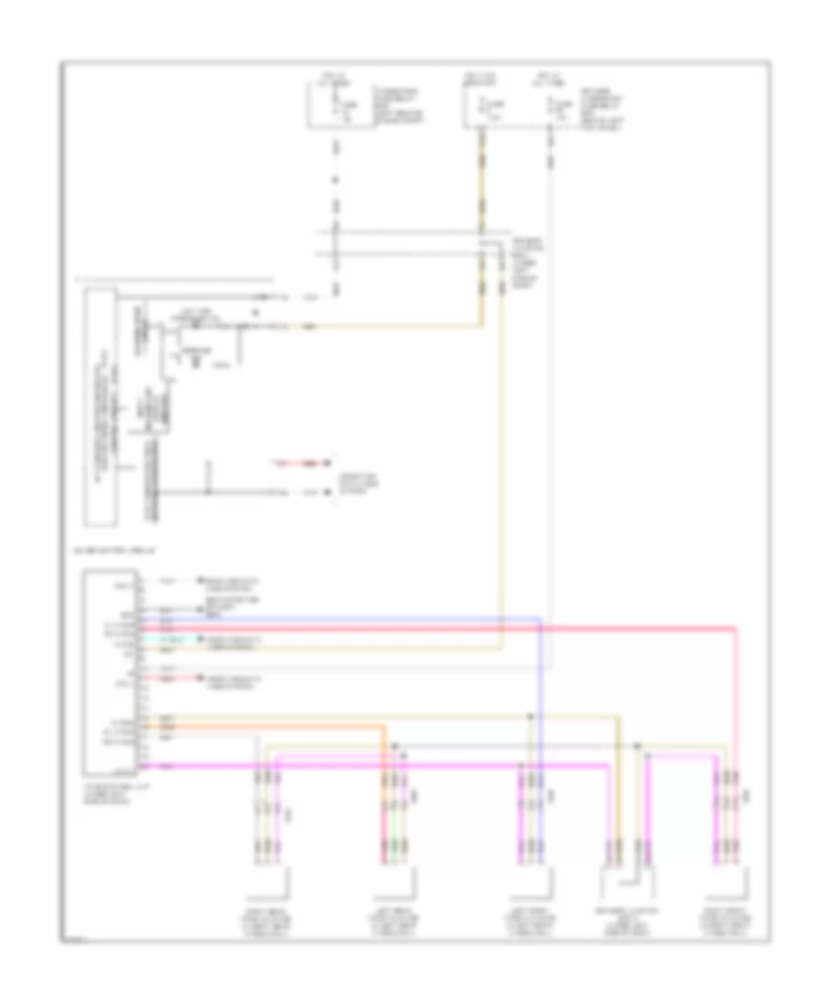
Tire Pressure Monitoring Wiring Diagram for Acura TSX 2011

Tire Pressure Monitoring Wiring Diagram for Acura TSX 2011 https://portal-diagnostov.com/license.html
https://portal-diagnostov.com/license.html Automotive Electricians Portal FZCO Automotive Electricians Portal FZCO
Få adgang til alle ledningsdiagrammer bilDownload PDF file

List of elements for Tire Pressure Monitoring Wiring Diagram for Acura TSX 2011:

  • (2.4l)
  • (3.5l)
  • (behind center of dash) g503
  • (mid) unit
  • 2.4l
  • 3.5l
  • 5v stabilizer circuit/controller area network controller
  • C205
  • C304
  • C602
  • C651
  • Can h
  • Can l
  • Computer data lines system
  • Control circuits
  • Display information
  • Driver's junction box 1 (under left side of dash)
  • Driver's junction box 2 (under left side of dash)
  • Driver's under-dash fuse/relay box (behind left kick panel)
  • Fast controller area network transceiver
  • Fl ini sig
  • Fr ini sig
  • Fuse 10a
  • Fuse 7.5a
  • Gauge control module
  • Gnd
  • Hot at all times
  • Hot in on or start
  • Ig1
  • Ini gnd
  • K-line
  • Left front tpms initiator (in left front wheelwell)
  • Left rear tpms initiator (in left rear wheelwell)
  • Lf ini+
  • Low tire pressure ind
  • Message ind
  • Multi
  • N14
  • P20
  • Pnk
  • Red
  • Right front tpms initiator (in right front wheelwell)
  • Right rear tpms initiator (in right rear wheelwell)
  • Rl ini sig
  • Rr ini sig
  • Tpms control unit (under left side of dash)
  • Under-hood fuse/relay box (left rear of engine compt)
  • Warning drive circuit