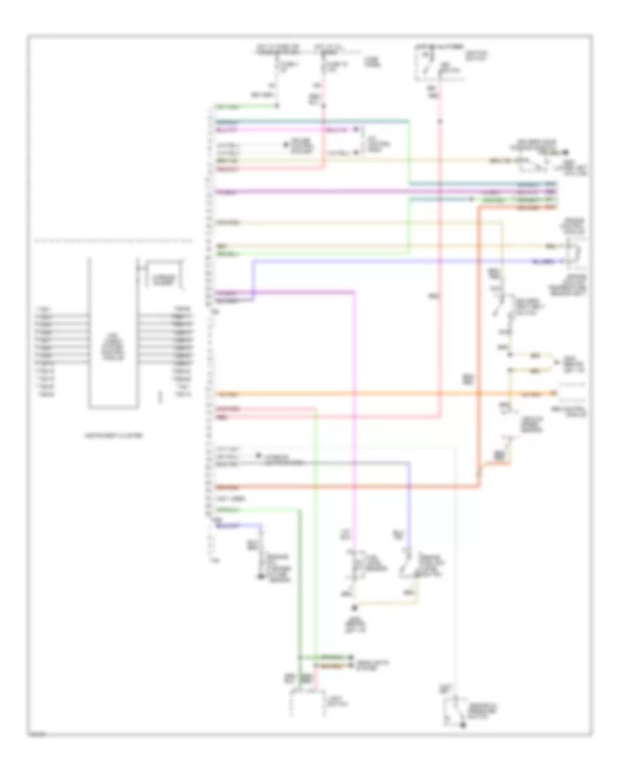
WARNING SYSTEMS
Warning Systems Wiring Diagram for Audi A4 1996
List of elements for Warning Systems Wiring Diagram for Audi A4 1996:
- (behind left i/p)
- (lower left a-pillar)
- (not used)
- 15a
- 86s
- A/c control head
- Abs control module
- C10
- C13
- C22
- Cruise control system
- Driver's door contact switch
- Driver's seat belt switch
- Engine control module
- Engine coolant level switch
- Engine coolant temperature sensor (ect)
- Engine oil pressure
- Engine oil temper- ature sensor
- Fuel level sensor
- Fuse 15 10a
- Fuse 3 5a
- Fuse panel
- G202
- G202 (behind left i/p)
- G900
- Headlights system
- Hot at all times
- Hot w/ park or headlights on
- Ignition switch
- Instrument cluster
- Interior lights system
- Key switch
- Light switch
- Mini check system control module
- Nca
- Red
- Switch
- T26
- T26-1
- T26-12
- T26-16
- T26-18
- T26-19
- T26-20
- T26-25
- T26-26
- T26-3
- T26-4
- T26-6
- T26-7
- T26-8
- T26-9
- T26a
- T26a-11
- T26a-13
- T26a-14
- T26a-18
- T26a-19
- T26a-20
- T26a-23
- T26a-24
- T26a-26
- T4a
- T4a-1
- Vehicle speed sensor
- Warning buzzer
 English