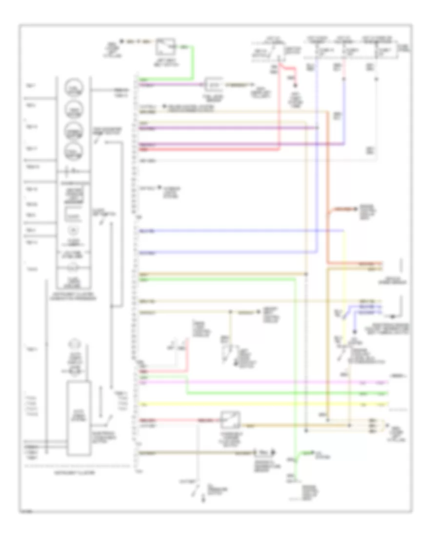
WARNING SYSTEMS
Warning Systems Wiring Diagram for Audi A6 1995
List of elements for Warning Systems Wiring Diagram for Audi A6 1995:
- (6 bulbs)
- 86s
- A/c
- A/c system
- Anti- theft system (1996)
- Auto check system
- Auto- check display illum.
- C10
- Center console light booster
- Clock
- Clock light
- Clock set button
- Cruise control system (vehicle speed output)
- Dimmer switch
- Electronic engine coolant temperature (ect) thermal switch
- Electronic voice check button
- Engine control module (ecm)
- Engine coolant level (elc) warning switch
- Engine oil
- Fluid level
- Fuel gauge
- Fuel level sensor
- Fuse 15 5a
- Fuse 7 5a
- Fuse 8 15a
- Fuse panel
- G404 (near left taillight)
- G900 (lower left "a" pillar)
- Hot at all times
- Hot in run or acc
- Hot w/ park or headlights on
- Ignition switch
- Illum. lights
- Instrument cluster
- Instrument cluster combination processor
- Interior lights system
- Key-in switch
- Left front door contact switch
- Left seat belt switch
- Memory seat control module
- Oil pressure switch
- Radio
- Rear lamp control module
- Red
- Sensor
- Speed- ometer
- Switch
- System
- T10/1
- T10/2
- T10/3
- T14
- T14-1
- T14-11
- T14-12
- T14-2
- T14-3
- T14-4
- T14-8
- T26
- T26-10
- T26-11
- T26-14
- T26-15
- T26-17
- T26-2
- T26-22
- T26-3
- T26-7
- T26-8
- T26a
- T26a-11
- T26a-12
- T26a-16
- T26a-18
- T26a-3
- T26a-6
- T26a-7
- T4m
- T4m-2
- Tach- ometer
- Temp gauge
- Temperature
- Trip odometer reset switch
- Vehicle speed sensor
- Voltage stabilizer
- Washer
- Windshield
 English