WARNING SYSTEMS
Brake Wear Sensor Wiring Diagram for Audi A7 Prestige 2013

List of elements for Brake Wear Sensor Wiring Diagram for Audi A7 Prestige 2013:
- (left kick panel) g44
- (right kick panel) g43
- Computer data lines system
- Fuse 30a
- Fuse panel d (under left side of dash)
- G50 (left side of luggage compt)
- Hot at all times
- Instrument cluster control module
- Left front brake pad wear sensor
- Left rear brake pad wear sensor
- Right front brake pad wear sensor
- Right rear brake pad wear sensor
- T16c
- T17c
- T32
- T32a
- Vehicle electrical system control module (left end of dash)
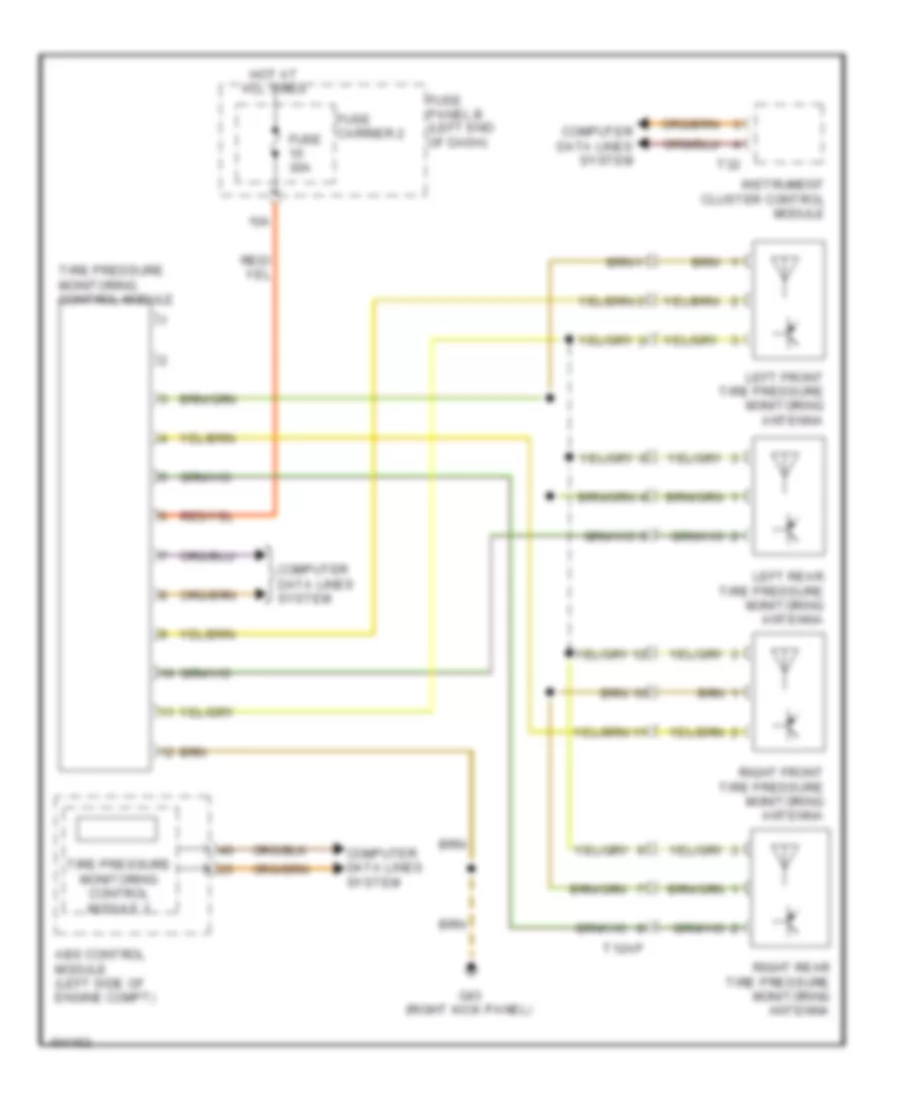
Tire Pressure Monitoring Wiring Diagram for Audi A7 Prestige 2013
List of elements for Tire Pressure Monitoring Wiring Diagram for Audi A7 Prestige 2013:
- 10a
- Abs control module (left side of engine compt)
- Computer data lines system
- Fuse 30a
- Fuse carrier 2
- Fuse panel b (left end of dash)
- G43 (right kick panel)
- Hot at all times
- Instrument cluster control module
- Left front tire pressure monitoring antenna
- Left rear tire pressure monitoring antenna
- Right front tire pressure monitoring antenna
- Right rear tire pressure monitoring antenna
- T12ap
- T32
- Tire pressure monitoring control module
- Tire pressure monitoring control module 2