WARNING SYSTEMS
Chime Wiring Diagram for BMW 540i 1998

List of elements for Chime Wiring Diagram for BMW 540i 1998:
- Chime module (above driver footwell)
- Driver's door jamb switch
- Fuse f24 5a
- Fuse panel 1
- General module
- Hot at all times
- Instrument cluster
- Interior lights system
- X10113
- X1108 (driver footwell)
- X11176
- X173 (driver door sill)
- X253
- X254
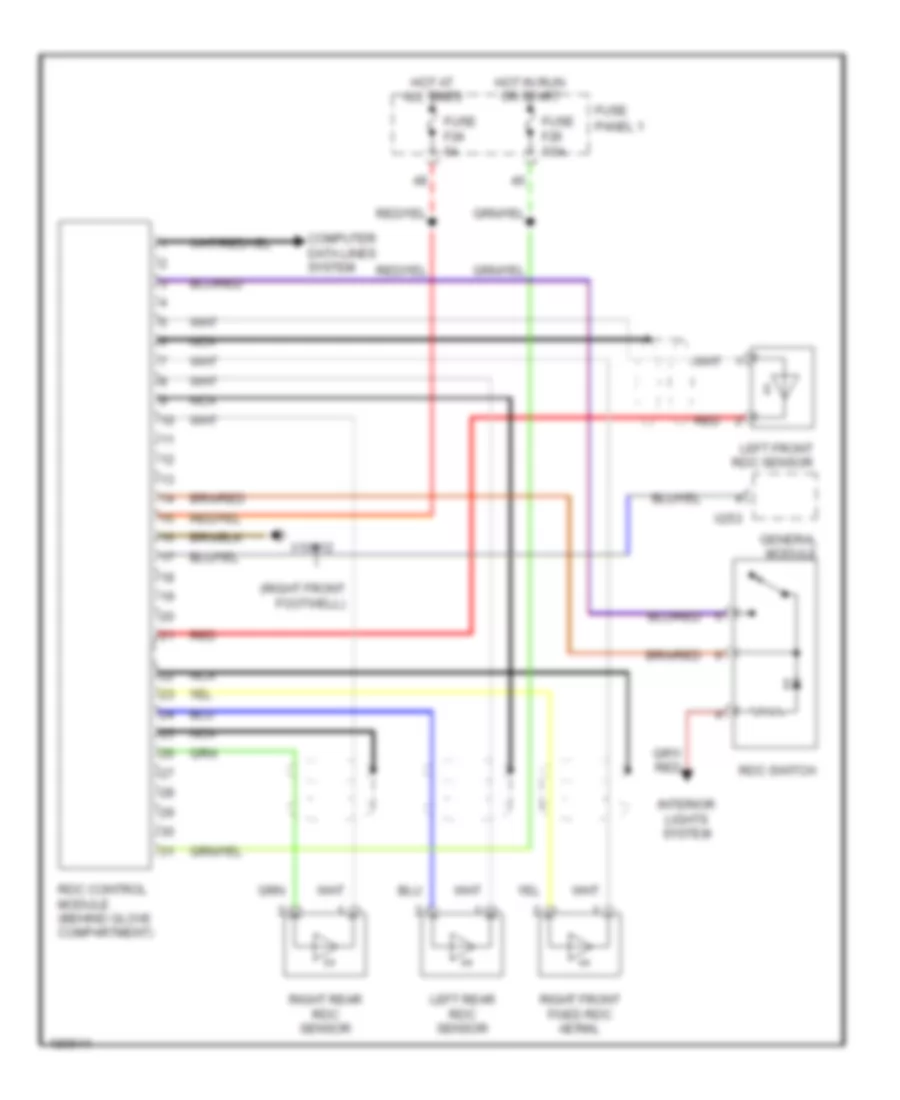
Tire Pressure Monitoring Wiring Diagram for BMW 540i 1998
List of elements for Tire Pressure Monitoring Wiring Diagram for BMW 540i 1998:
- (right front footwell)
- Computer data lines system
- Fuse f20 7.5a
- Fuse f24 5a
- Fuse panel 1
- General module
- Hot at all times
- Hot in run or start
- Interior lights system
- Left front rdc sensor
- Left rear rdc sensor
- Nca
- Rdc control module (behind glove compartment)
- Rdc switch
- Red
- Right front fixed rdc aerial
- Right rear rdc sensor
- X10012
- X253