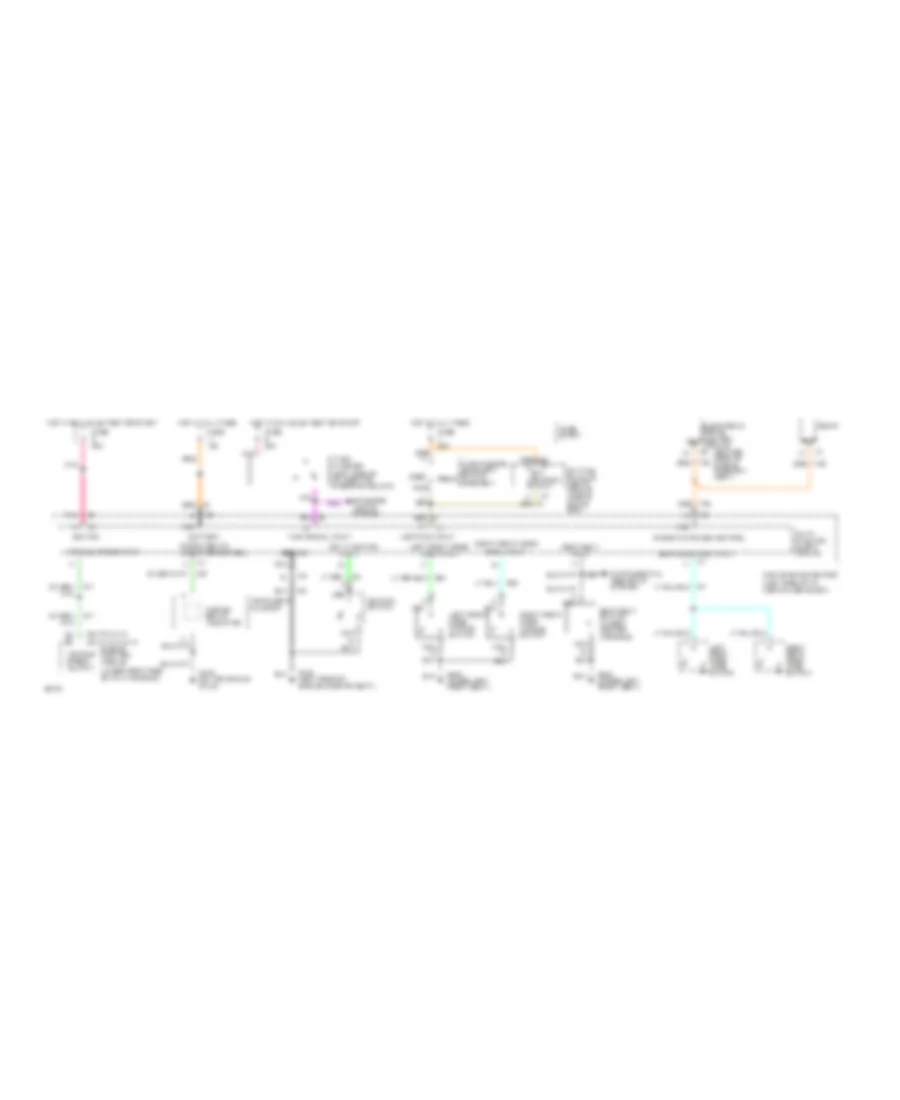
WARNING SYSTEMS
Warning System Wiring Diagrams for Chevrolet Beretta 1994
List of elements for Warning System Wiring Diagrams for Chevrolet Beretta 1994:
- (center rear of engine compart- ment)
- (left side of i/p, above fuse block)
- (left side of i/p, right of steering column)
- (under right side of i/p at shroud)
- (v6 vin m) (l4 vin a & 4)
- A nca
- Bat
- Battery
- C2 c2
- Convenience center
- Daytime running lights module (above glove box)
- Electronic brake control module c2
- Engine control module
- Exterior lights system
- Fasten belts indicator
- Fasten belts indicator control
- Fuse 15a
- Fuse 20a
- Fuse block
- G104 (left rear of engine compartment)
- G130 (on transaxle stud)
- G300 (under left front seat)
- Ground
- Head
- Hot at all times
- Hot in run, bulb test or start
- Ignition
- Ignition switch
- Input
- Instrument cluster
- Key in ignition
- Left rear door jamb switch
- Left front door
- Left front door handle switch
- Lights on input
- Lights-on output
- Multi- function alarm module
- Nca
- Nca d
- Off
- Open input
- Parasitic power control
- Park
- Pnk
- Radio
- Rear door open input
- Right front door
- Right front door handle switch
- Right rear door jamb switch
- Seat belt
- Seat belt switch (under center console)
- Turn flasher
- Turn signal input
- Turn/hazard- headlight switch assembly
- Vehicle speed input
- Vehicle speed output
 English