WARNING SYSTEMS
Chime Wiring Diagram for Ford F-150 XLT 2013

List of elements for Chime Wiring Diagram for Ford F-150 XLT 2013:
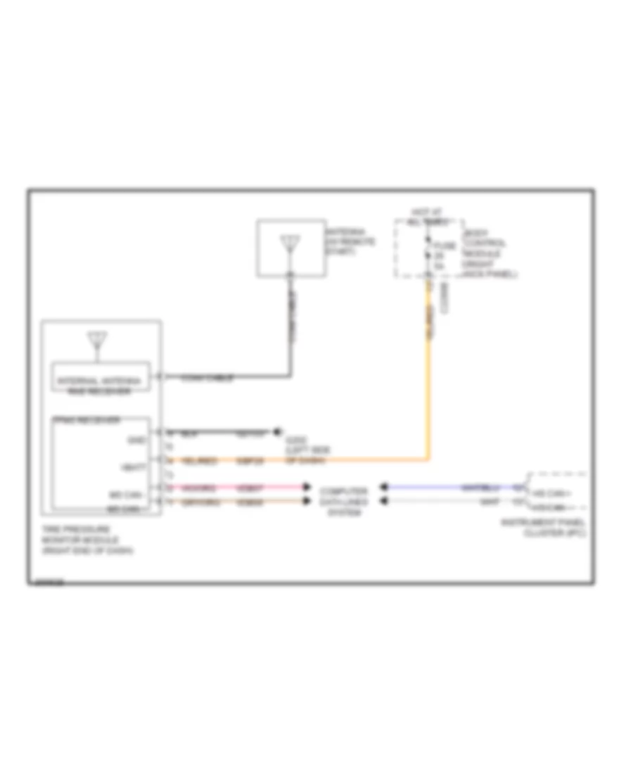
Tire Pressure Monitoring Wiring Diagram for Ford F-150 XLT 2013
List of elements for Tire Pressure Monitoring Wiring Diagram for Ford F-150 XLT 2013: