WARNING SYSTEMS
Chime Wiring Diagram for Ford Mustang Shelby GT500 2009

List of elements for Chime Wiring Diagram for Ford Mustang Shelby GT500 2009:
- (rear of right front door) right front door ajar switch
- Anti-theft hood switch (right front of engine compt)
- Auto
- Brake fluid level switch (left rear of engine compt, on brake fluid reservoir)
- Buckle status
- Bussed electrical center (bec) (right front of engine compt)
- C1035a
- C1035c
- C2041b
- C2280b
- C2280c
- C2280e
- Computer data lines system
- D11
- Driver buckle sw
- Driver door ajar sw
- Driver safety belt buckle switch (in driver's seat belt buckle)
- E11
- Early production
- F11
- Fuse 20a
- G100 (right side of radiator support)
- G201 (behind right side of dash)
- G203 (right "a" pillar)
- G204 (left kick panel)
- G205 (right "a" pillar)
- G402 (right rear of luggage compt)
- Headlamp off
- Headlamp on
- Hot at all times
- Hs can+
- Hs can-
- Ignition switch
- Instrument cluster
- Interior lights system
- Key in ign
- Key in ignition switch
- Late production
- Lcl
- Left front door ajar switch (rear of left front door)
- Lh turn sig
- Low
- Low brake fluid rtn
- Low brake fluid sw
- Luggage compartment lid release solenoid (rear of trunk lid, on latch assembly)
- Main light switch
- Multifunction switch
- Off
- Park
- Park brake switch
- Parking brake switch (on parking brake lever assembly)
- Pass buckle sw
- Pass door ajar sw
- Passenger safety belt buckle switch (in driver's seat belt buckle)
- Primary ril
- Rcl
- Restraints control module (behind lower center of dash)
- Rh turn sig
- Ril
- S112
- S209
- S220
- S222
- S301
- S406
- S503
- S602
- Smart junction box (sjb) (right kick panel)
- Tan
- Trunk ajar switch
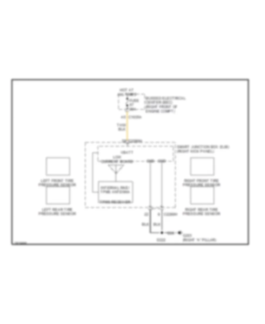
Tire Pressure Monitoring Wiring Diagram for Ford Mustang Shelby GT500 2009
List of elements for Tire Pressure Monitoring Wiring Diagram for Ford Mustang Shelby GT500 2009:
- Bussed electrical center (bec) (right front of engine compt)
- C1035a a5
- C2280h
- Fuse 30a
- G203 (right "a" pillar)
- Gnd
- Hot at all times
- Internal rke/ tpms antenna
- Left front tire pressure sensor
- Left rear tire pressure sensor
- Low current board
- Right front tire pressure sensor
- Right rear tire pressure sensor
- S222
- Smart junction box (sjb) (right kick panel)
- Tpms receiver
- Vbatt