WARNING SYSTEMS
Chime Wiring Diagram for Honda CR-V EX 2008

List of elements for Chime Wiring Diagram for Honda CR-V EX 2008:
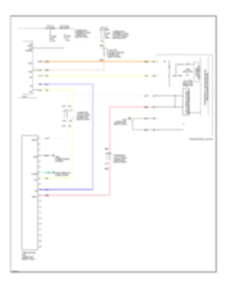
Tire Pressure Monitoring Wiring Diagram for Honda CR-V EX 2008
List of elements for Tire Pressure Monitoring Wiring Diagram for Honda CR-V EX 2008: