WARNING SYSTEMS
Chime Wiring Diagram for Honda CR-V LX 2013

List of elements for Chime Wiring Diagram for Honda CR-V LX 2013:
- (in right "c" pillar)
- 0) off 1) park 2) auto 3) head
- 5v on/off
- A13
- A20
- A21
- Amp
- B-can transceiver
- B22
- B24
- B29
- B33
- B34
- B40
- Brake indicator
- C108
- C116
- Can h
- Can l
- Circuit
- Circuit 5v control
- Circuit dimming
- Combination light switch
- Computer data lines system
- Converter dc/dc
- D11
- D17
- Door indicator
- Driver's door switch (on left "b" pillar)
- Driver's junction box 2 (left side of dash)
- Driver's micu
- Driver's seat belt buckle switch (in driver's seat belt buckle assembly)
- Except lx w/o navigation & w/o res
- Exl w/o navigation & w/ res & exl w/ navigation & w/o res
- F-can transceiver
- Fail-safe circuit
- Front passenger's door switch (on right "b" pillar)
- Front passenger's seat belt buckle switch (in front passenger's seat belt buckle assembly)
- Fuse 10a
- Fuse 7.5a
- G502 (under middle of dash)
- G601 (under driver's seat)
- G602 (under front passenger's seat)
- Gauge control module
- Headlight switch
- Hot at all times
- Hot in acc or on
- Hot in on or start
- Ignition key switch
- Indicator drive circuit
- Left rear door switch (in left "c" pillar)
- Lights on indicator
- Low oil pressure indicator
- Mixing
- Oil pressure switch (on right front of engine, above oil filter)
- P11
- Parking brake switch (under left side of dash)
- Pcm (left side of engine compt)
- Pnk
- Q16
- Red
- Right rear door switch
- Seat belt reminder indicator
- Speaker
- Srs unit (under front of center console)
- Stabillzing 10v
- Tailgate indicator
- Turning-on forced
- Under- dash fuse/ relay box (under left side of dash)
- Under- hood fuse/ relay box (on left side of engine compt)
- W/ res
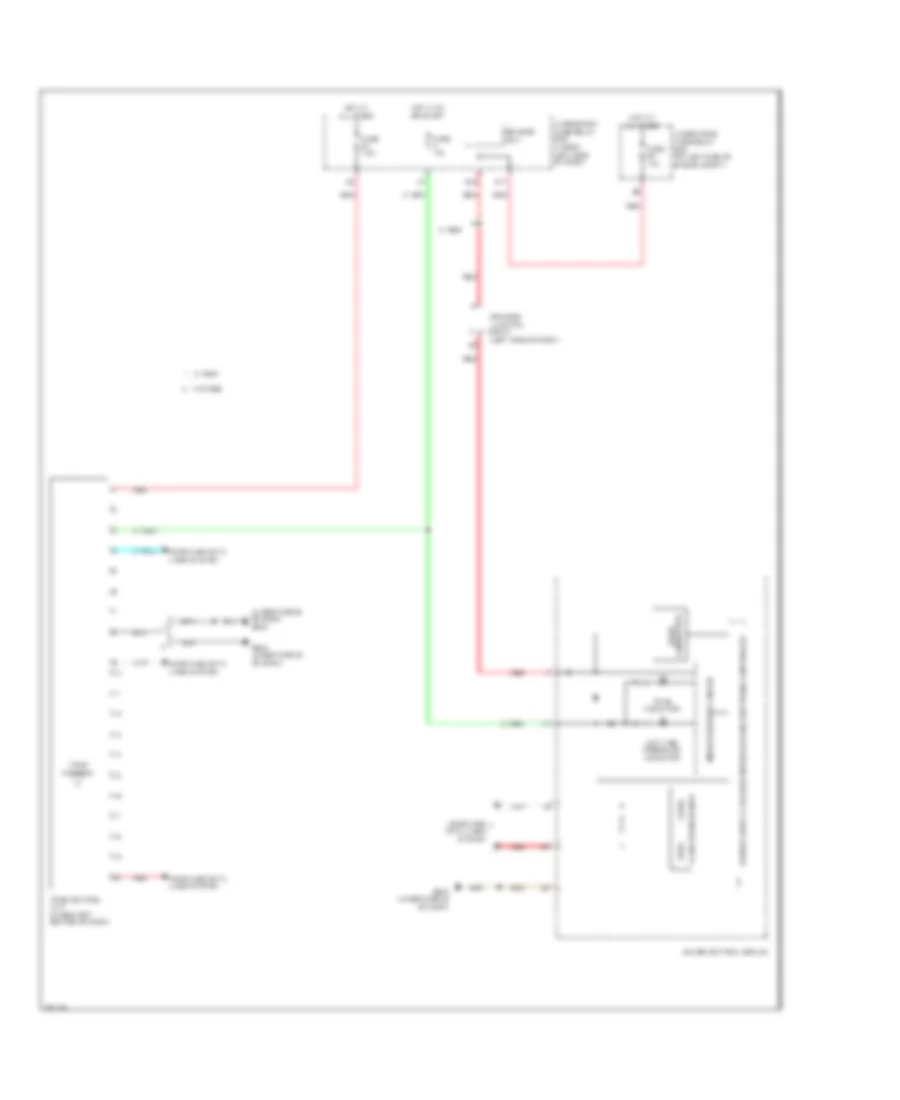
Tire Pressure Monitoring Wiring Diagram for Honda CR-V LX 2013
List of elements for Tire Pressure Monitoring Wiring Diagram for Honda CR-V LX 2013:
- (under middle of dash) g503
- Can h
- Can l
- Computer data lines system
- D17
- Dc/dc converter
- Driver's junction box 2 (left side of dash)
- Driver's micu
- F-can transceiver
- Fuse 10a
- Fuse 7.5a
- G502 (under middle of dash)
- G503 (under middle of dash)
- Gauge control module
- Hot at all times
- Hot in on or start
- Indicator drive circuit
- Low tire pressure indicator
- Q16
- Red
- Tpms antenna
- Tpms control unit (under left center of dash)
- Tpms indicator
- Under-dash fuse/relay box (under left side of dash)
- Under-hood fuse/relay box (on left side of engine compt)
- W/ res
- W/o res